ICRL-U-8M12-G60 Manual
Safety Instructions
2021-02
8
1.9.3. Relevant for Use in Explosion Hazard Areas (Hazardous Locations, Class I,
Division 2)
This equipment is exclusively suitable for use in Class I, Division 2,
Groups A, B, C, and D or non-hazardous locations.
WARNING – EXPLOSION HAZARD – DO NOT DISCONNECT EQUIPMENT UNLESS POWER HAS BEEN
SWITCHED OFF OR THE AREA IS KNOWN TO BE NON-HAZARDOUS.
WARNING - EXPLOSION HAZARD - SUBSTITUTION OF ANY COMPONENT MAY IMPAIR SUITABILITY
FOR CLASS I, DIVISION 2.
Avertissement - Risque d'explosion - Ne pas débrancher tant que le circuit est sous tension à moins que
l'emplacement soit connu pour ne contenir aucune concentration de gaz inflammable.
Avertissement - Risque d'explosion - La substitution de tout composant peut rendre ce matériel incompatible
pour une utilisation en classe I, division 2.
This device is an open-type device that is to be installed in an enclosure suitable for the environment.
Exclusively use the device for the application cases specified by the manufacturer. Failure to follow these
instructions can impair device protection.
1.9.4. FCC Note
The ICRL-U-8M12-G60 complies with part 15 of the FCC rules. Operation is subject to the following two
conditions: (1) this device may not cause harmful interference; (2) this device must accept any interference
received, including interference that may cause undesired operation.
Appropriate testing has established that this device fulfills the requirements of a class A digital device in line
with part 15 of the FCC regulations.
These requirements are designed to provide sufficient protection against interference when the device is being
used in a business environment.The device creates and uses high frequencies and can also radiate these
frequencies. If it is not installed and used in accordance with this operating manual, it can cause radio
transmission interference.The use of this device in a residential area can also cause interference, and in this
case the user is obliged to cover the costs of removing the interference.
Alternative
2Relevant for North America: The total voltage supply complies with the requirements as per NEC
Class 2.
Alternative
3
All of the following requirements are complied with: The power supply complies with the
requirements for a safety extra-low voltage (SELV) as per IEC/EN 60950-1. In both voltage inputs,
install a fuse suitable for DC voltage in the plus conductor of the power supply. In both voltage
inputs, connect the minus conductor to the ground potential. If the minus conductor is not
connected to the ground potential, also install an external fuse in the minus conductor. See the
note below.
Note: Back-up fuse for each voltage input when supplied via 1 input.
Nominal rating: 1 A ... 4 A
Characteristic: slow blow
Note: Back-up fuse for each voltage input when supply is via 2 inputs.
Nominal rating: 1A ... 2 A
Characteristic: slow blow
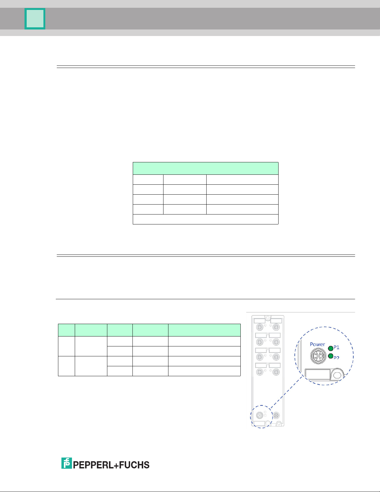
Requirements for Connecting the Supply Voltage