Pepperl+Fuchs M-LB-21 Series User manual

ISO9001
3
Functional Safety
M-LB-(Ex-)2000-System
Surge Protection Barriers
PROCESS AUTOMATION
MANUAL

With regard to the supply of products, the current issue of the following document is applicable: The General Terms of
Delivery for Products and Services of the Electrical Industry, published by the Central Association of the Electrical
Industry (Zentralverband Elektrotechnik und Elektroindustrie (ZVEI) e.V.) in its most recent version as well as the
supplementary clause: "Expanded reservation of proprietorship"
Functional Safety M-LB-(Ex-)2000-System

Functional Safety M-LB-(Ex-)2000-System
Content
2019-02
3
1 Introduction . . . . . . . . . . . . . . . . . . . . . . . . . . . . . . . . . . . . . . . . . . . . . . . . . . . 4
1.1 Content of this Document. . . . . . . . . . . . . . . . . . . . . . . . . . . . . . . . . . . . . 4
1.2 Safety Information . . . . . . . . . . . . . . . . . . . . . . . . . . . . . . . . . . . . . . . . . . . 5
1.3 Symbols Used . . . . . . . . . . . . . . . . . . . . . . . . . . . . . . . . . . . . . . . . . . . . . . 6
2 Product Description. . . . . . . . . . . . . . . . . . . . . . . . . . . . . . . . . . . . . . . . . . . . . 7
2.1 Function . . . . . . . . . . . . . . . . . . . . . . . . . . . . . . . . . . . . . . . . . . . . . . . . . . . 7
2.2 Interfaces . . . . . . . . . . . . . . . . . . . . . . . . . . . . . . . . . . . . . . . . . . . . . . . . . . 8
2.3 Marking . . . . . . . . . . . . . . . . . . . . . . . . . . . . . . . . . . . . . . . . . . . . . . . . . . . . 8
2.4 Standards and Directives for Functional Safety . . . . . . . . . . . . . . . . . . 8
3 Planning . . . . . . . . . . . . . . . . . . . . . . . . . . . . . . . . . . . . . . . . . . . . . . . . . . . . . . 9
3.1 System Structure. . . . . . . . . . . . . . . . . . . . . . . . . . . . . . . . . . . . . . . . . . . . 9
3.2 Assumptions . . . . . . . . . . . . . . . . . . . . . . . . . . . . . . . . . . . . . . . . . . . . . . 10
3.3 Safety Function and Safe State . . . . . . . . . . . . . . . . . . . . . . . . . . . . . . . 11
3.4 Characteristic Safety Values . . . . . . . . . . . . . . . . . . . . . . . . . . . . . . . . . 13
3.5 Useful Lifetime . . . . . . . . . . . . . . . . . . . . . . . . . . . . . . . . . . . . . . . . . . . . . 14
4 Mounting and Installation . . . . . . . . . . . . . . . . . . . . . . . . . . . . . . . . . . . . . . . 15
4.1 Mounting. . . . . . . . . . . . . . . . . . . . . . . . . . . . . . . . . . . . . . . . . . . . . . . . . . 15
4.2 Configuration . . . . . . . . . . . . . . . . . . . . . . . . . . . . . . . . . . . . . . . . . . . . . . 15
5 Operation . . . . . . . . . . . . . . . . . . . . . . . . . . . . . . . . . . . . . . . . . . . . . . . . . . . . 16
5.1 Proof Test . . . . . . . . . . . . . . . . . . . . . . . . . . . . . . . . . . . . . . . . . . . . . . . . . 16
6 Maintenance and Repair . . . . . . . . . . . . . . . . . . . . . . . . . . . . . . . . . . . . . . . . 18
7 Application Examples . . . . . . . . . . . . . . . . . . . . . . . . . . . . . . . . . . . . . . . . . . 19
8 List of Abbreviations . . . . . . . . . . . . . . . . . . . . . . . . . . . . . . . . . . . . . . . . . . . 24

2019-02
4
Functional Safety M-LB-(Ex-)2000-System
Introduction
1Introduction
1.1 Content of this Document
This document contains information for usage of the device in functional safety-related
applications. You need this information to use your product throughout the applicable stages
of the product life cycle. These can include the following:
• Product identification
• Delivery, transport, and storage
• Mounting and installation
• Commissioning and operation
• Maintenance and repair
• Troubleshooting
• Dismounting
• Disposal
The documentation consists of the following parts:
• Present document
• Instruction manual
•Manual
•Datasheet
Additionally, the following parts may belong to the documentation, if applicable:
• EU-type examination certificate
• EU declaration of conformity
• Attestation of conformity
• Certificates
• Control drawings
• FMEDA report
• Assessment report
• Additional documents
For more information about Pepperl+Fuchs products with functional safety,
see www.pepperl-fuchs.com/sil.
Note!
This document does not substitute the instruction manual.
Note!
For full information on the product, refer to the instruction manual and further documentation
on the Internet at www.pepperl-fuchs.com.

Functional Safety M-LB-(Ex-)2000-System
Introduction
2019-02
5
1.2 Safety Information
Target Group, Personnel
Responsibility for planning, assembly, commissioning, operation, maintenance,
and dismounting lies with the plant operator.
Only appropriately trained and qualified personnel may carry out mounting, installation,
commissioning, operation, maintenance, and dismounting of the product.
The personnel must have read and understood the instruction manual and the further
documentation.
Intended Use
The device is only approved for appropriate and intended use. Ignoring these instructions will
void any warranty and absolve the manufacturer from any liability.
The device is developed, manufactured and tested according to the relevant safety standards.
Use the device only
• for the application described
• with specified environmental conditions
• with devices that are suitable for this safety application
Improper Use
Protection of the personnel and the plant is not ensured if the device is not used according
to its intended use.

2019-02
6
Functional Safety M-LB-(Ex-)2000-System
Introduction
1.3 Symbols Used
This document contains symbols for the identification of warning messages and of
informative messages.
Warning Messages
You will find warning messages, whenever dangers may arise from your actions.
It is mandatory that you observe these warning messages for your personal safety
and in order to avoid property damage.
Depending on the risk level, the warning messages are displayed in descending
order as follows:
Informative Symbols
Action
This symbol indicates a paragraph with instructions. You are prompted to perform an action
or a sequence of actions.
Danger!
This symbol indicates an imminent danger.
Non-observance will result in personal injury or death.
Warning!
This symbol indicates a possible fault or danger.
Non-observance may cause personal injury or serious property damage.
Caution!
This symbol indicates a possible fault.
Non-observance could interrupt the device and any connected systems and plants,
or result in their complete failure.
Note!
This symbol brings important information to your attention.

Functional Safety M-LB-(Ex-)2000-System
Product Description
2019-02
7
2 Product Description
2.1 Function
This manual describes solely the safety function and safe state of the surge protection barrier
as part of the surge protection system.
Surge Protection Barrier M-LB-21**(.SP)
The device limits induced transients of different causes, e. g. lightning or switching operations.
The limitation is achieved by diverting the current to earth and limiting the signal loop voltage
during the duration of the overvoltage pulse.
The device is mounted on a 35 mm x 7.5 mm DIN mounting rail according to EN 60715.
The DIN mounting rail is used to attach the device in the switch cabinet and is responsible
for grounding the surge protection barriers. The DIN rail mounting ensures a grounding
connection with the lowest possible resistance of the device.
The devices are available with screw terminals or spring terminals. The type code
of the versions of the devices with spring terminals has the extension ".SP".
Surge Protection Barrier M-LB-Ex-21**(.SP)
The device limits induced transients of different causes, e. g. lightning or switching operations.
The limitation is achieved by diverting the current to earth and limiting the signal loop voltage
during the duration of the overvoltage pulse.
The device is used for intrinsic safety applications.
The device is mounted on a 35 mm x 7.5 mm DIN mounting rail according to EN 60715.
The DIN mounting rail is used to attach the device in the switch cabinet and is responsible
for grounding the surge protection barriers. The DIN rail mounting ensures a grounding
connection with the lowest possible resistance of the device.
The devices are available with screw terminals or spring terminals. The type code
of the versions of the devices with spring terminals has the extension ".SP".
Danger!
Danger to life from wrong usage of the device
The protection of the safety loop against overvoltage is not the safety function
of the surge protection barrier.
The surge protection barrier protects applications and equipment against voltage surges
caused by lightning or switching operations.
The statement concerning the safety function of the surge protection barrier solely
describes the effect on safety loops in which the barrier is installed.
The barrier acts in the safety loops as a simple pass through element.

2019-02
8
Functional Safety M-LB-(Ex-)2000-System
Product Description
2.2 Interfaces
The device has the following interfaces.
• Safety relevant interfaces: protected signal lines
• Non-safety relevant interfaces: none
2.3 Marking
The *-marked letters of the type code are placeholders for versions of the device.
2.4 Standards and Directives for Functional Safety
Device specific standards and directives
System-specific standards and directives
Note!
For corresponding connections see datasheet.
Pepperl+Fuchs GmbH
Lilienthalstraße 200, 68307 Mannheim, Germany
Internet: www.pepperl-fuchs.com
Surge protection barrier M-LB-21**(.SP), M-LB-Ex-21**(.SP) Up to SIL 3
Functional safety IEC/EN 61508, part 1 –7, edition 2010:
Functional safety of electrical/electronic/programmable
electronic safety-related systems (manufacturer)
Functional safety IEC/EN 61511, part 1 –3, edition 2016:
Functional safety –Safety instrumented systems
for the process industry sector (user)

Functional Safety M-LB-(Ex-)2000-System
Planning
2019-02
9
3 Planning
3.1 System Structure
3.1.1 Low Demand Mode of Operation
If there are two control loops, one for the standard operation and another one
for the functional safety, then usually the demand rate for the safety loop is assumed
to be less than once per year.
The relevant safety parameters to be verified are:
•thePFD
avg value (average Probability of dangerous Failure on Demand)
and the T1value (proof test interval that has a direct impact on the PFDavg value)
• the SFF value (Safe Failure Fraction)
• the HFT architecture (Hardware Fault Tolerance)
3.1.2 High Demand or Continuous Mode of Operation
If there is only one safety loop, which combines the standard operation and safety-related
operation, then usually the demand rate for this safety loop is assumed to be higher
than once per year.
The relevant safety parameters to be verified are:
•thePFHvalue(Probability of dangerous Failure per Hour)
• Fault reaction time of the safety system
• the SFF value (Safe Failure Fraction)
• the HFT architecture (Hardware Fault Tolerance)
3.1.3 Safe Failure Fraction
The safe failure fraction describes the ratio of all safe failures and dangerous detected failures
to the total failure rate.
SFF = (s+ dd) / (s+ dd + du)
A safe failure fraction as defined in IEC/EN 61508 is only relevant for elements or (sub)systems
in a complete safety loop. The device under consideration is always part of a safety loop
but is not regarded as a complete element or subsystem.
For calculating the SIL of a safety loop it is necessary to evaluate the safe failure fraction
of elements, subsystems and the complete system, but not of a single device.
Nevertheless the SFF of the device is given in this document for reference.

2019-02
10
Functional Safety M-LB-(Ex-)2000-System
Planning
3.2 Assumptions
The following assumptions have been made during the FMEDA:
• The device will be used under average industrial ambient conditions comparable
to the classification "stationary mounted" according to MIL-HDBK-217F.
Alternatively, operating stress conditions typical of an industrial field environment
similar to IEC/EN 60654-1 Class C with an average temperature over a long period
of time of 40 ºC may be assumed. For a higher average temperature of 60 ºC,
the failure rates must be multiplied by a factor of 2.5 based on experience.
A similar factor must be used if frequent temperature fluctuations are expected.
• The control loop is considered to be either isolated from ground (except i. e. components
within the protection module), or one of the protected lines is directly connected to ground.
In both cases, a failure mode leads to a safe reaction or has no effect, so the worst case
is assumed to be a no effect failure.
• Failure rate based on the Siemens standard SN 29500.
• Failure rates are constant, wear is not considered.
• The control loop has a hardware fault tolerance of 0and it is a type Adevice.
A SFF value for this device is not given, since this value has to be calculated in conjunction
with the connected field device, as described in the following section.
• The devices M-LB-(Ex-)2114(.SP) do not withstand conducted RF immunity tests
(10 V according to IEC/EN 61000-4-6).
The devices M-LB-(Ex-)2114(.SP) and M-LB-(Ex-)2144(.SP) do not withstand immunity
tests against conducted common mode disturbances at spot frequencies
(100 V according to IEC/EN 61000-4-16).
Cause is that the limit values of the protective elements for the application
are lower than the test limits required by the standards. The user has to decide whether
the devices are suitable for the application or whether the devices with higher voltage limits
must be used.
Application
The surge protection barrier and the connected device (transmitter, isolator or actuator)
have to be considered in combination. The PFDavg/PFH budget of the device categories
in the entire safety loop is:
• Actuator (valve) 40 %
• Transmitter (sensor) 25 %
• Isolator 10 %
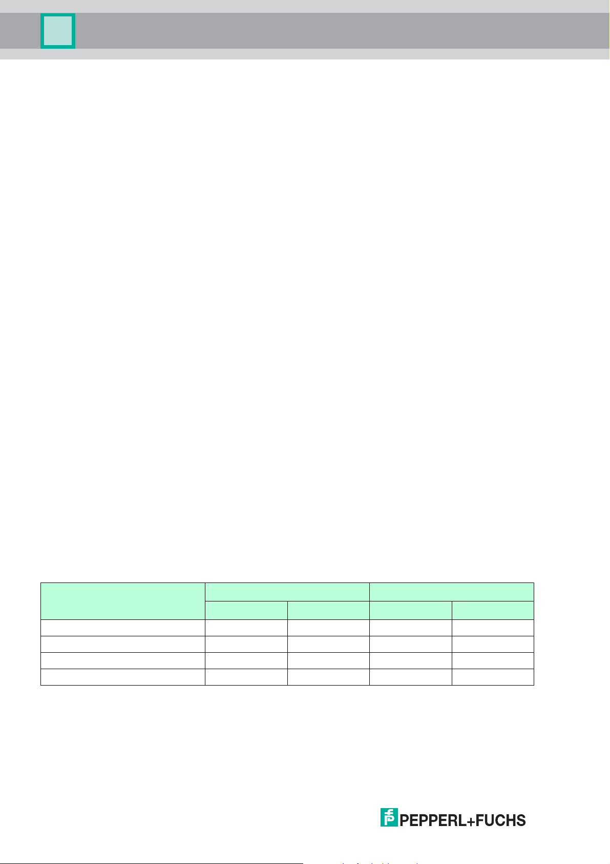
As an overview for the SIL2 or SIL3 safety loop this means:
Device category SIL2 SIL3
PFH PFDavg PFH PFDavg
Total 10-6 10-2 10-7 10-3
Actuator (40 %) 4 x 10⁻⁷ 4 x 10⁻³ 4 x 10⁻⁸ 4 x 10⁻⁴
Transmitter (25 %) 2.5 x 10⁻⁷ 2.5 x 10⁻³ 2.5 x 10⁻⁸ 2.5 x 10⁻⁴
Isolator (10 %) 10-7 10-3 10-8 10-4
Table 3.1 Overview PFDavg/PFH budget

Functional Safety M-LB-(Ex-)2000-System
Planning
2019-02
11
3.3 Safety Function and Safe State
The safety function of the surge protection barriers depends on the signal loop to which
it is attached. The interference on safety relevant signals (e. g. 4 mA to 20 mA analog signal)
that pass through the devices was evaluated.
Observe the PFH/PFDavg values in the functional safety manual and the specified calculation
rules. The devices fulfil the requirements for SIL 3 and can be used to pass safety relevant
signals through in applications up to SIL 3.
The surge protection barriers limit induced transients of different causes, e. g. lightning
or switching operations. This protection function itself is not the safety function of the device.
Safe State
The safe state depends on the application. There are 6 different applications:
• Digital input (NAMUR signal)
Lead breakage and short circuit are out of range and counted as safe failures.
• Digital output (de-energized to safe –DTS)
Lead breakage and short circuit interrupt the energy transfer to the field and are counted
as safe failures.
• Analog input (4 mA to 20 mA)
Lead breakage and short circuit are out of range and counted as safe failures.
• Analog output (4 mA to 20 mA)
Lead breakage and short circuit interrupt the energy transfer to the field and are counted
as safe failures.
• Resistance thermometer (RTD)
Measurement current = 200 µA (i. e. KFD2-UT2-1)
- R 3137 (Pt1000 at 600 °C)
- R 60 (Pt100 at -100 °C)
Wire resistance = 35 (1000 m total and 0.5 mm2Cu)
Lead breakage and short circuit are out of range and counted as safe failures.
• Thermocouple (TC)
- U 80 mV (type E at 1000 K)
- U -10 mV (type E at -270 K)
Lead breakage and short circuit lead to plausible temperature readings and were rated
dangerous undetected. Special values apply, see Table 3.2. If you are using a signal
converter with line fault detection, the values for standard 2-wire applications apply.
For the evaluation, all deviations from the input signal were rated as dangerous undetected,
if the deviations are
• greater than the specified leakage current or
• greater than the 3 line resistance.
The user must observe the valid range for the signals in the application and react accordingly
if this range is left.
The values given in the following table are calculated for 2-wire applications as field devices
are usually connected by more than one wire. For the calculation, add the numbers from
the respective column to the numbers given for the safety loop. They are already summarized
for the respective application.

2019-02
12
Functional Safety M-LB-(Ex-)2000-System
Planning
Safety Function
The safety function of the surge protection barrier is to behave like a piece of copper wire,
passing through the process signal without being altered.
Reaction Time
The reaction time is < 1 ms.
Note!
The fault indication output is not safety relevant.
Note!
See corresponding datasheets for further information.

Functional Safety M-LB-(Ex-)2000-System
Planning
2019-02
13
3.4 Characteristic Safety Values
1oo1 Structure
The characteristic safety values like PFD, PFH, SFF, HFT and T1are taken
from the FMEDA report. Observe that PFD and T1are related to each other.
The function of the devices has to be checked within the proof test interval (T1).
Parameters Characteristic values
Assessment type Full assessment
Device type A
Mode of operation Low demand mode or high demand mode
Safety function 1
1The safe state of the surge protection barrier depend on the application.
Pass through the signal
HFT 0
SIL 2
2The maximum safety integrity level of the safety loop in which the device might be used depends on the performance values
of the whole safety loop or the elements of the safety loop. See chapter 7.
3
Devices AI, AO, BI, BO, RTD TC
s17.2 FIT 0 FIT
du 1.1 FIT 18.2 FIT
dd 0 FIT 0 FIT
total (safety function) 18.3 FIT 18.2 FIT
no part 0.3 FIT 0.3 FIT
MTBF 3
3acc. to SN 29500. This value includes failures which are not part of the safety function/MTTR = 8 h.
The value is calculated for one safety function of the device.
3163 years 3171 years
PFH 1.05 x 10⁻⁹ 1/h 1.82 x 10⁻⁸ 1/h
PFDavg for T1= 1 year 4.60 x 10⁻⁶ 7.97 x 10⁻⁵
PFDavg for T1= 2 years 9.20 x 10⁻⁶ 1.59 x 10⁻⁴
PFDavg for T1= 3 years 1.38 x 10⁻⁵ 2.39 x 10⁻⁴
PTC 100 % 100 %
Reaction time 4
4Since the disturbance cannot be distinguished from the signal under EMC conditions according to EN/IEC 61326-3-1,
the reaction time increases to 100 ms.
<1ms
Table 3.2

2019-02
14
Functional Safety M-LB-(Ex-)2000-System
Planning
3.5 Useful Lifetime
Although a constant failure rate is assumed by the probabilistic estimation this only applies
provided that the useful lifetime of components is not exceeded. Beyond this useful lifetime,
the result of the probabilistic estimation is meaningless as the probability of failure significantly
increases with time. The useful lifetime is highly dependent on the component itself and
its operating conditions –temperature in particular. For example, the electrolytic capacitors
can be very sensitive to the operating temperature.
This assumption of a constant failure rate is based on the bathtub curve, which shows
the typical behavior for electronic components.
Therefore it is obvious that failure calculation is only valid for components that have
this constant domain and that the validity of the calculation is limited to the useful lifetime
of each component.
It is assumed that early failures are detected to a huge percentage during the installation
and therefore the assumption of a constant failure rate during the useful lifetime is valid.
However, according to IEC/EN 61508-2, a useful lifetime, based on general experience,
should be assumed. Experience has shown that the useful lifetime often lies within a range
periodofabout8to12years.
As noted in DIN EN 61508-2:2011 note N3, appropriate measures taken by the manufacturer
and plant operator can extend the useful lifetime.
Our experience has shown that the useful lifetime of a Pepperl+Fuchs product can be higher
if the ambient conditions support a long life time, for example if the ambient temperature
is significantly below 60 °C.
Please note that the useful lifetime refers to the (constant) failure rate of the device.
The effective life time can be higher.

Functional Safety M-LB-(Ex-)2000-System
Mounting and Installation
2019-02
15
4 Mounting and Installation
Mounting and Installing the Device
1. Observe the safety instructions in the instruction manual.
2. Observe the information in the manual.
3. Observe the requirements for the safety loop.
4. Connect the device only to devices that are suitable for this safety application.
5. Check the safety function to ensure the expected output behavior.
4.1 Mounting
Mounting and Grounding the Device
1. Mount the device on a 35 mm x 7.5 mm DIN mounting rail according to EN 60715.
2. Ground the device via the DIN mounting rail.
4.2 Configuration
A configuration of the device is not necessary and not possible.

2019-02
16
Functional Safety M-LB-(Ex-)2000-System
Operation
5Operation
Operating the device
1. Observe the safety instructions in the instruction manual.
2. Observe the information in the manual.
3. Use the device only with devices that are suitable for this safety application.
4. Correct any occurring safe failures within 8 hours.
Take measures to maintain the safety function while the device is being repaired.
5.1 Proof Test
According to IEC/EN 61508-2 a recurring proof test shall be undertaken to reveal
potential dangerous failures that are not detected otherwise.
Check the function of the subsystem at periodic intervals depending on the applied PFDavg
in accordance with the characteristic safety values. See chapter 3.4.
It is under the responsibility of the plant operator to define the type of proof test
and the interval time period.
Equipment required:
• 2 digital multimeter with an accuracy of 0.1 %
• Variable power supply 0 V DC to 50 V DC and current limitation
Proof Test Procedure
1. Put out of service the entire safety loop. Protect the application by means of other measures.
2. Prepare a test set-up, see figures below.
3. Test the devices for the application they are used for.
4. Set back the device to the original settings for the application after the test.
Danger!
Danger to life from missing safety function
If the safety loop is put out of service, the safety function is no longer guaranteed.
• Do not deactivate the device.
• Do not bypass the safety function.
• Do not repair, modify, or manipulate the device.

Functional Safety M-LB-(Ex-)2000-System
Operation
2019-02
17
Leakage Current Measurement
Resistance Measurement
Device Step Measurement Expected result
M-LB-2112(.SP) 11Vbetweenterminals4and5
1Vbetweenterminals5and4
Leakage current below 5 A
M-LB-Ex-2114(.SP) 1
2
3
1Vbetweenterminals4and5
1Vbetweenterminals5and4
1 V between terminal 4 and ground
1 V between terminal 5 and ground
Leakage current below 10 A
M-LB-2142(.SP) 130 V between terminals 4 and 5
30 V between terminals 5 and 4
Leakage current below 3 A
M-LB-Ex-2144 (.SP) 1
2
3
30 V between terminals 4 and 5
30 V between terminals 5 and 4
30 V between terminal 4 and ground
30 V between terminal 5 and ground
Leakage current below 6 A
Table 5.1
Device Step Measurement Expected result
M-LB-21*2(.SP) 1Resistance between terminals 2 and 5 Resistance below 3.0
M-LB-Ex-21*4(.SP) 1
2
Resistance between terminals 2 and 5
Resistance between terminals 3 and 4
Resistance below 3.0
Table 5.2

2019-02
18
Functional Safety M-LB-(Ex-)2000-System
Maintenance and Repair
6 Maintenance and Repair
Maintaining, Repairing or Replacing the Device
In case of maintenance, repair or replacement of the device, proceed as follows:
1. Implement appropriate maintenance procedures for regular maintenance of the safety loop.
2. While the device is maintained, repaired or replaced, the safety function does not work.
Take appropriate measures to protect personnel and equipment while the safety function
is not available.
Secure the application against accidental restart.
3. Do not repair a defective device. A defective device must only be repaired
by the manufacturer.
4. If there is a defect, always replace the device with an original device.
Danger!
Danger to life from missing safety function
Changes to the device or a defect of the device can lead to device malfunction.
The function of the device and the safety function is no longer guaranteed.
Do not repair, modify, or manipulate the device.

Functional Safety M-LB-(Ex-)2000-System
Application Examples
2019-02
19
7 Application Examples
This chapter shows how to integrate a surge protection barrier into a safety loop.
Integration of a Surge Protection Barrier into a Safety Loop
To define and calculate the safety relevant values for a low demand safety loop,
you have to determine the following basic parameters first:
1. the signal characteristic of the safety loop: analog or digital,
2. the signal direction of the safety loop as seen from the perspective of the safety-rated
programmable logic controller (SPLC): input or output,
3. the safe state of the field device allocated to the surge protection barrier,
4. the mode of operation: low demand mode, high demand mode or continuous mode
5. the required SIL level of the safety loop.
After the safety loop is defined, assign a surge protection barrier to the field device.
Create a basic overview as shown below.
Figure 7.1 Example of a complete safety loop with assigned surge protection barriers
In principle, the performance values of the surge protection barriers have to be added
to the performance values of the field device or the safety-rated programmable logic controller
(SPLC). By doing so, it is assumed that the surge protection barrier is a part of this device.
Verify with these new values if the necessary SIL level can be achieved.
You find examples of the various applications in the following section.
PFD
1
PFD
3
PFD
2
PFD
5
PFD
4
++ ++
13
46
2
5
13 15
12
9
10
7
14
11
8
1
2
OUT CHK PWR
S2
S1
S3
III
13
46
2
5
13 15
12
9
10
7
14
11
8
1
2
OUT CHK PWR
S2
S1
S3
III
1
2
3
4
5
6
1
2
3
4
5
6
1
2
3
4
5
6
1
2
3
4
5
6
40 %25 %
Logic system
Sensor Digital
input Actuator
Digital
output
Analog
input
Sensor Analog
output Actuator
10 %
Signal path
10 %
Signal path
15 %
SPLC
50 %
Actuator and signal path
35 %
Sensor system and signal path

2019-02
20
Functional Safety M-LB-(Ex-)2000-System
Application Examples
Example 1 - Digital Input - NAMUR NE 22 Signals
When using a standard isolated barrier from Pepperl+Fuchs, it is possible to implement low
demand safety loops with SIL 2 with a standard NAMUR NE 22 digital input signal.
A sample configuration would be the isolated barrier KCD2-SR-Ex1.LB with surge protection
barrier M-LB -Ex-2***.
Basic parameters:
1. Signal characteristic of the safety loop: 2-wire application
2. Signal direction of the safety loop as seen from the perspective of the safety-rated
programmable logic controller (SPLC): input
3. Safe state of the field device allocated to the surge protection barrier: de-energized
4. Required SIL level of the safety loop: SIL 2
Figure 7.2 Sample configuration consisting of a surge protection barrier and an isolated barrier
SIL level calculation of the safety loop
• SFF value of the safety loop is as demanded for type A components > 60 %.
• As an optimum, the combination of surge protection barrier and isolated barrier claims
10 % of the overall PFDavg maximum 1 x 10⁻² and therefore has a PFDavg <1 x 10⁻³
The isolated barrier KCD2-SR-Ex1.LB has the following performance values:
Use for calculation of du of the isolated barrier the PFDavg formula given in IEC 61508:
•PFD
avg = 1/2 x du x T1
•du = 2 x PFDavg / T1= 2 x 2.05 x 10-4 / 8760 [h] = 47 FIT
total 254 FIT
PFDavg for T1= 1 year 2.05 x 10⁻⁴
SFF 81.5 %
Table 7.1
24 V
Input
Non-hazardous area
Hazardous area
Isolated barrier
Surge protection
barrier
This manual suits for next models
4
Table of contents
Other Pepperl+Fuchs Surge Protector manuals