Assembly and Operation Manual
4 DELIVERY SET
4.1 Standard delivery set
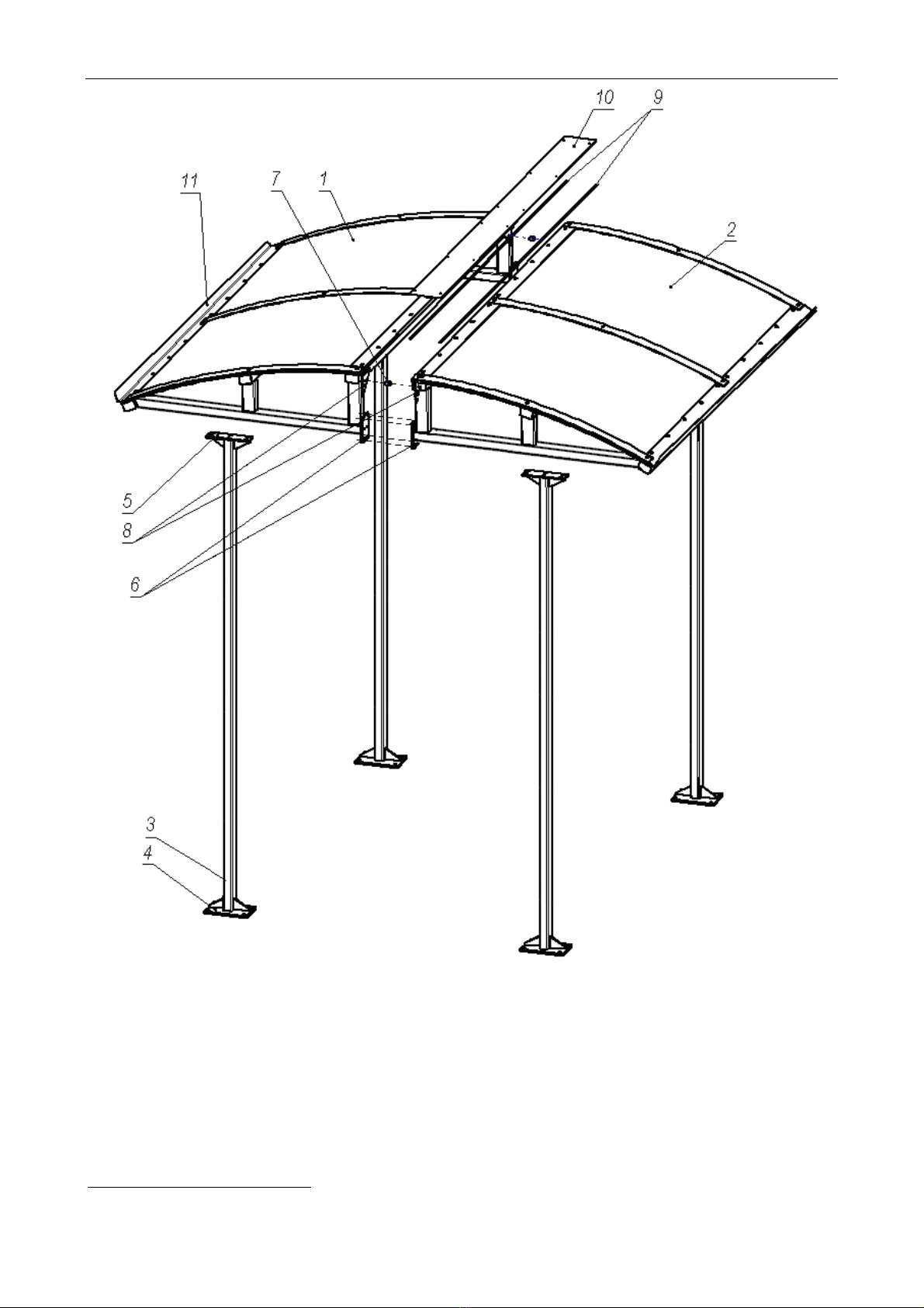
Primary parts:
Left roof section ......................................................................................................... 1
Right roof section ...................................................................................................... 1
Post .......................................................................................................................... 4
Bushing ..................................................................................................................... 2
Jointing plate ............................................................................................................. 1
Sealing element ......................................................................................................... 4
Fasteners:
Hex socket screw М6×30 .........................................................................................20
Hex socket screw М6×40 .......................................................................................... 4
Hex socket screw М8×50 .......................................................................................... 2
Nut М6 ....................................................................................................................... 8
Nut М8 ....................................................................................................................... 2
Washer 6 ................................................................................................................. 24
Washer 8 ................................................................................................................... 2
Spring washer 6 ...................................................................................................... 24
Spring washer 8 ........................................................................................................ 2
Self-tapping screw 4.2×16 ........................................................................................12
In-line documentation:
Assembly & operation manual with warranty card ..................................................... 1
Package:
Package box .............................................................................................................. 3
4.2 Optional equipment supplied on request
Optional equipment fittings:
As addition to the standard delivery set, the canopy can be supplied with optional
equipment fittings used in the canopy installation depending on adjacent equipment:
Mounting brackets
Connecting posts
Note:
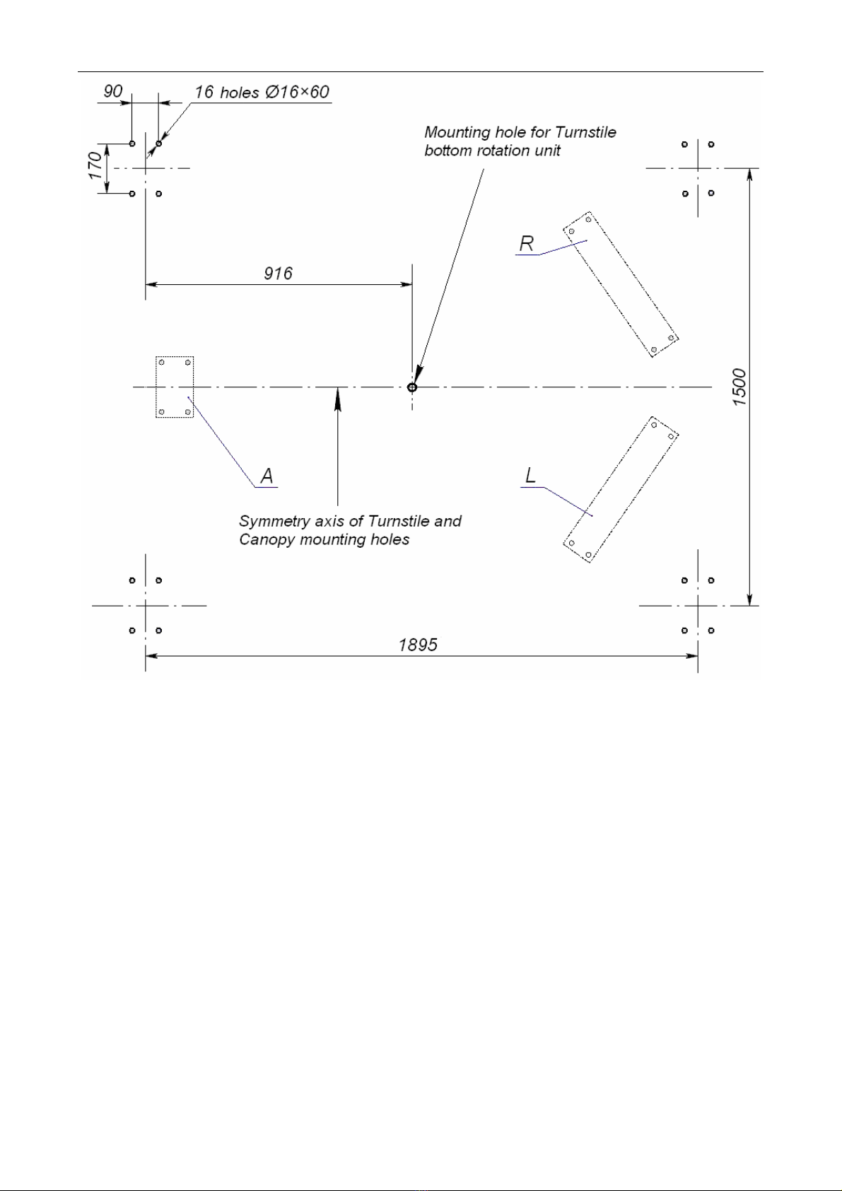
This Manual gives information on attachment of the canopy to the turnstile
by the «Turnstile-Canopy» bracket (see sect. 8.3). Fittings of any other type, their
number and installation are dependent on the entrance layout. They should be
specified in general mounting documentation for the entrance and cannot be given in
this Manual.
Mounting hardware:
We advise using the following metal anchors for medium heavy and heavy fixings in solid
and hard foundations like concrete (400 grade or higher), stone, etc.:
Metal anchor with bolt М10×60 PFG IR 10-15 («SORMAT», Finland) .....................16
Installation of the canopy on other types of foundations may require different mounting
hardware.
4