Perfect Aire PROAIRE SPOT6800 User manual

SPOT COOLER
MODEL: SPOT6800
OWNER’S MANUAL

SAFETY & PRECAUTIONS CONTINUEDCONTINUED
CONTENTS (Continued)
SAFETY AND PRECAUTIONS............................................................................................................1
TECHNICAL SPECIFICATIONS ..........................................................................................................2
ELECTRICAL SCHEMATIC DIAGRAM ...............................................................................................2
PRODUCT STRUCTURE....................................................................................................................3
INSTALLATION INSTRUCTIONS ........................................................................................................4
OPERATION INSTRUCTIONS ............................................................................................................5
CONDENSATE TANK..........................................................................................................................6
USAGE REQUIREMENTS ..................................................................................................................7
MAINTENANCE AND CARE GUIDE...................................................................................................7
CORRECT DISPOSAL OF THIS PRODUCT.......................................................................................7
TROUBLESHOOTING ........................................................................................................................8
IMPORTANT NOTE:
• This spot cooler MUST be installed in accordance to all local governing codes and ordinances
• This spot cooler MUST be installed as specied by these instructions
• Installing this spot cooler requires basic mechanical and electrical skills and should be installed by a
qualied professional.
This User Manual provides specic instructions on the installation and operation of your air conditioner. It is
important that all SAFETY AND INSTALLATIONS instructions below are followed

1
SAFETY & PRECAUTIONS (Continued)
• Do NOT store unit with condensate in the condensate tank.
• Do not drink any water that is drained from the air conditioner.
• Use a dry and clean cloth to clean any dust or debris on the power plug.
• This unit is not intended to be operated on a boat or vehicle. Failure to follow guidelines may result in safety
hazards.
• Please do not stick ngers or hands in the vent.
• This appliance is not intended for use by children. Children should be supervised and should not play on or around the
appliance.
• DO NOT operate or install your unit in a potentially explosive,combustible, or corrosive gas environment.
• Keep your unit away from ammable materials and open ame.
• DO NOT move the unit while it is operating. Before moving the unit,rst turn o the power, then unplug the system from the
power source.
• DO NOT tilt or operate the unit on its side or back. This will damage the compressor.
• DO NOT place objects on top of your unit.
• DO NOT insert your hand or any other object into the cold air supply duct(s).
• If repair is needed, please contact the after-sales service department at the place of purchase.
CAUTION
BEFORE YOU BEGIN: READ THESE INSTRUCTIONS CAREFULLY AND COMPLETELY

2
SAFETY & PRECAUTIONS CONTINUEDCONTINUED
TECHNICAL SPECIFICATIONS (Continued)
Model Number SPOT6800
Cooling Capacity 5300 Btu/hr
Voltage/Phase/Hz 115V/1Ph/60Hz
Rated Current 7.1 A
Indoor Air Flow 135 ft3/min. (230m3/h)
Refrigerant Type R410a
Refrigerant Amount 10.6 oz. (300g)
Ambient Temperature Range 68 °F – 109 °F (20 °C – 43 °C)
Net Weight 56 lbs (25.5 kg)
Gross Weight 62 lbs (28.3 kg)
Product Dimension (Width/Depth/Height) 18.3 in/11.3 in/23.1 in (465*287*586)mm 5
ELECTRICAL SCHEMATIC DIAGRAM

3
PRODUCT STRUCTURE (Continued)
FRONT
BACK
POWER SWITCH
CONDENSATE FULL INDICATOR
COLD AIR
OUTLET HOSE
ASSEMBLY
FILTER SCREEN
DRAIN PORT
HOT AIR EXHAUST
HANDLE
HANDLE
CASTER
FILTER
CONDENSATE TANK

4
SAFETY & PRECAUTIONS CONTINUEDCONTINUED
INSTALLATION INSTRUCTIONS (Continued)
COLD AIR EXHAUST HOSE ASSEMBLY:
1. Align the locking tabs of the Cold Exhaust Pipe to the attachment channels (Dent) located on the exhaust elbow as
shown in the diagram below (Fig. 1). A
2. Insert the locking tabs into the attachment channels (Dent) and turn until they lock into place (Fig. 1). A
3. Align the locking tabs on the elbow with the attachment channels (Dent) on the connection plate (Fig. 1). B
4. Insert the locking tabs into the attachment channels (Dent) and turn until they lock into place (Fig. 1). B
ATTACH COLD AIR EXHAUST HOSE ASSEMBLY TO UNIT:
1. Using the supplied screws, attach the connection plate to the cabinet (Fig.2).
FIG 1
FIG 2
Dent
B
A

5
OPERATION INSTRUCTIONS (Continued)
OPERATION INSTRUCTIONS
• To power ON the unit: press the power switch to the “I” position. On initial startup the, compressor
and fan motor will start immediately. It may take a few minutes for the air to start feeling cold.
• To power OFF the unit: press the power switch (rocker) to the “O” position. The compressor and
fan motor will stop.
COMPRESSOR OVERHEAT PROTECTION
This unit is equipped with an overload protector that is designed to shut down the unit temporarily if the
compressor overheats. This overheating can be caused by extremely high or low voltage or by excessively
high ambient temperature.
When the overload protection device is activated, the machine will continue to blow air but the compressor
will not be operational and the air will not be cold. If the thermal overload protection is frequently activated,
please nd and eliminate the cause before using the machine.
WATER ALARM
When the volume of condensate in the tank reaches approximately 75% of its ll capacity, the “Condensate
Full” sound buzzer will activate. The compressor and fan motor will stop once this occurs.
When the condensate tank is full, turn o the unit by pressing the power switch to the “O” position. The
“Water Full” indicator sound buzzer will stop. Remove the condensate tank and dump the contents. Re-
insert the empty tank into the unit and power on the air conditioner. The unit should start up normally after a
3-minute delay (Additional instructions in section “VII Condensate Tank.”)
ATTENTION: If the unit is powered o or if there is an electrical interruption, there is a minimum
three-minute delay after which, the unit will begin to operate again.

6
SAFETY & PRECAUTIONS CONTINUEDCONTINUED
OPERATION INSTRUCTIONS (Continued)
Emptying the condensate tank:
1. Shut o the air conditioner by pressing the power switch to the “O” position.
2. Locate the condensate tank.
3. Remove the condensate tank and empty the contents.
4. Re-install the condensate tank after emptying, making sure it is properly aligned.
5. Power on the unit. There is a 3-minute delay for the compressor to start. Normal operation will resume
after time delay has ended.
6. Empty the condensate tank before moving the air conditioner to avoid any spills.
ADJUSTMENT RANGE AND OPERATION OF THE AIR DIRECTION
• The cold air duct can rotate around 360 degrees
• The cold air duct can be moved up and down by about 150 degrees.
CONDENSATE TANK
ATTENTION: When adjusting the air outlet angle of the cold
air duct, please hold the elbow for adjustment. Do not directly
hold the cold air duct for adjustment.
ATTENTION: The compressor has a 3-minute safety delay function. After emptying the tank, there will be
a 3-minute delay where only the fan will operate. After the 3-minutes have expired, the compressor will
activate and normal operation will resume.
• If the unit has not been operated for a long time, check the condensate tank before operating:
• Remove the condensate tank from the air conditioner and conrm the oat device inside the tank is
intact. If no issues are found with the oat device, re-install the condensate tank into the air conditioner,
making sure everything is aligned.
• Improper installation of the condensate tank may trigger the condensate alarm, unit malfunction, or
condensate leakage.

7
USAGE REQUIREMENTS (Continued)
CORRECT DISPOSAL OF THIS PRODUCT
This marking on the product, accessories or literature indicates that the product and its electronic accessories
should not be disposed of with other household waste at the end of their working life. To prevent possible harm
to the environment or human health from uncontrolled waste disposal, please separate these items from other
types of waste and recycle them responsibly to promote the sustainable reuse of material resources.
SPECIAL USER REMINDERS:
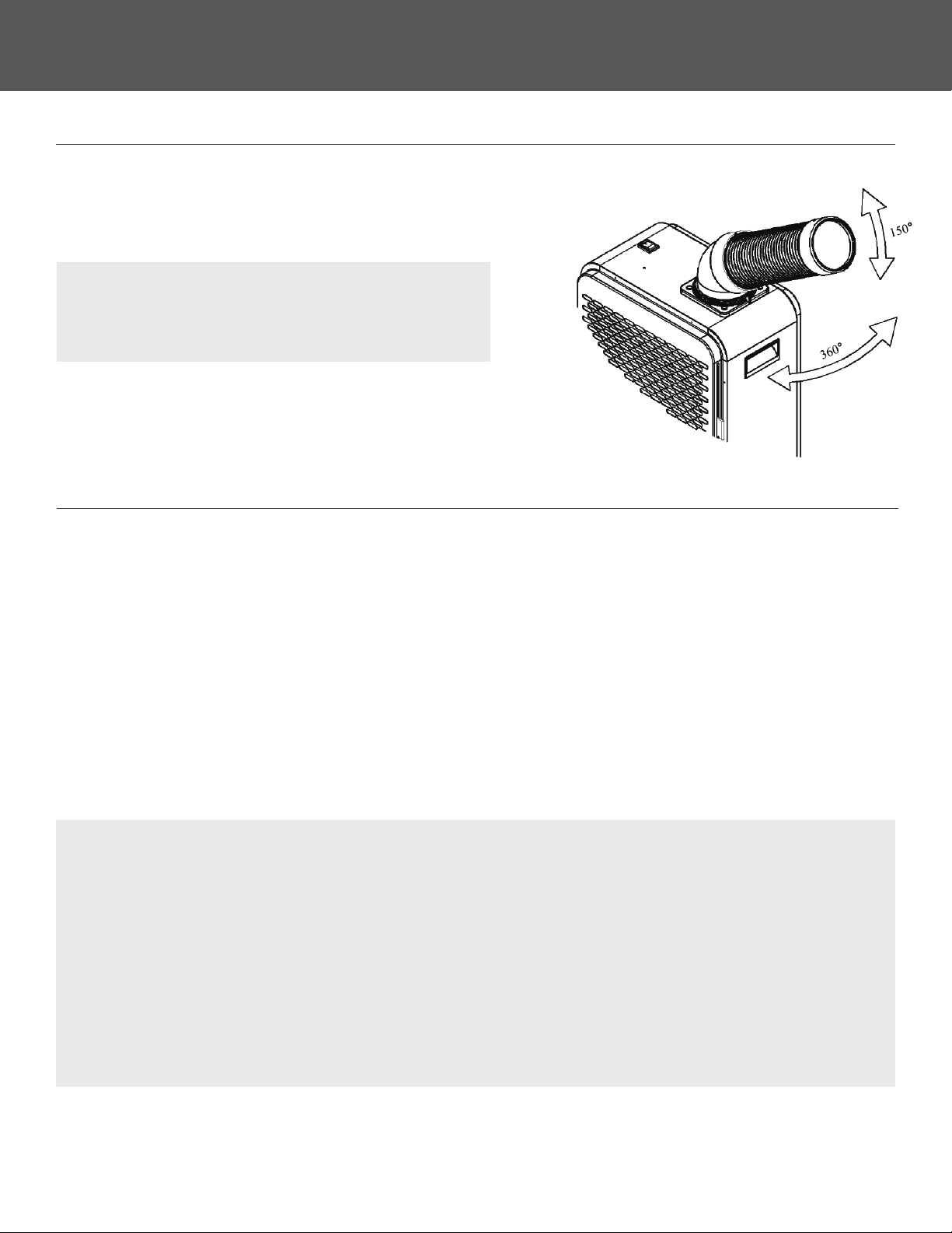
• When using the air conditioner, the air inlet and cold air duct should be away from walls and other
obstacles by at least 12in.
• The hot air outlet should be at least 32in away from any walls or obstacles.
• The air conditioner should be placed on a at and level surface. Operating the unit on slopes or uneven
surfaces may cause safety hazards and condensate leakage.
• Do not operate this machine in wet or damp places.
• Do not place obstacles in the front of the air inlet, cold air duct and hot air exhaust.
MAINTENANCE & CARE GUIDE
Periodically clean the screen lter on this unit. Dust and debris buildup will not allow proper airow and
may cause frosting and malfunction of the heat exchanger.
FILTER CLEANING:
1. Shut o the air conditioner.
2. Use a vacuum to remove any dust and dirt accumulated on the lter screen.
3. Use clean water to rinse o the remaining particles on the lter screen.
4. Once dry, re-install the lter screen into the air conditioner.
ATTENTION:
• Unplug the power cord from the machine when conducting maintenance or checks.
• When cleaning the exterior of the machine, do not use chemical agents or other cleaning solutions
that may damage the surfaces.
• Check if the power cord is damaged or broken. If so, replace it immediately.
• Check if any screws are loose. If so, tighten the screws.
• Before long-term storage, check condensate tank and empty any remaining condensate.
• The air conditioner must be stored upright.
• Do not lay the machine horizontally or upside down.
• Avoid storing the machine in locations with high temperature, rain, or direct sunlight.

8
SAFETY & PRECAUTIONS CONTINUEDCONTINUED
TROUBLESHOOTING (Continued)
CHECK THE FOLLOWING ITEMS FOR TROUBLESHOOTING:
Problem
Unit is not
Operating
Unit is not
cooling
Condensate
Leakage
Reason
Fuse is burnt
The power cord is loose or unplugged
Dirty heat exchanger
Hot exhaust fan failure
Ambient temperature is too high
Compressor capacitor is damaged
Blocked refrigerant tubing
Overly high or low input voltage
Compressor overload protection triggered
Compressor motor failure
Drainpipe opening is clogged
Condensate tank position is
not installed properly
Filter screen has dust and lth
Condensate oat switch is stuck
Condensate tank is full
Damaged condensate tank
Troubleshooting
Securely plug the unit into the wall outlet.
Ensure there is sucient power at the wall
outlet.
Have a professional or certied technician
replace the fuse.
Clean the heat exchanger surface to allow
for proper airow.
Repair or replace hot exhaust fan
or blower.
Do not operate the unit in areas with
excessively high ambient temperatures.
Replace compressor capacitor.
Replace blocked refrigerant tubing.
Use correct voltage.
Unit will restart after the compressor has
suciently cooled.
Repair or replace compressor.
Clean out any residue or debris in the
drain pipe.
Remove the condensate tank and
re-install properly.
Remove lter and clean.
Shut o the unit and empty condensate
tank before use.
Gently shake the tank to dislodge the oat
switch.
Repair or replace the condensate tank.
ATTENTION: If the air conditioner malfunctions or stops operating, shut o the machine immediately and
disconnect it from the wall outlet.


www.perfectaire.us
5401 Dansher Road
Countryside, IL 60525
Printed in China |1220_M383
Table of contents
Popular Accessories manuals by other brands

IMS
IMS RX5 instruction manual

PCB Piezotronics
PCB Piezotronics 288D01 Installation and operating manual

Intelbras
Intelbras IVA 7100 Dual user manual

Gembird
Gembird PB10-02 user manual

Cornelius
Cornelius Pre-Mix Dispenser Universal C-750 installation instructions

Magika
Magika MAGIKAREDREP installation guide