15192 Triton Lane
Huntington Beach, CA 92649
Tel: 206-888-6251
www.ppedm.com
e●drillTM QUICK START & MAINTENANCE GUIDE
This document is the property of PPedm, Inc. and contains proprietary and/or patented information and may not be reproduced in part or in whole without the express written permission of
the company. Perfect Point logo, Perfect PointTM and e●drillTM are trademarks of PPedm, Inc.. US and worldwide patents pending.
The purpose of this quick-start guide is to assist the operator in setting up and operating the e•drill system in as little time as possible. Refer to User
Guide for detailed programming and operation information. IMPORTANT!! Be sure ALL Installation procedures have been completed before operating
the system.
Prior to system use, is highly recommended the user be trained by PPedm in system use, service, and has read the
operators manual completely.
1. With the e•drill and Hand Held Terminal installed, and power connected to the Mobile Service Unit (MSU), locate the power switch on the
back service panel of the MSU and turn it to the “ON” (up) position.
2. The system will power up and after a few seconds the Hand Held Terminal touch screen will illuminate and display the last fastener
entry.
SELECTION OF PARAMETERS TO PERFORM A CUT:
1. Determine the type of fastener you are about to cut. If the screen of the Hand Held Terminal is not
illuminated, touch the screen to awaken it. Go to bottom right tabs on screen and select visual or select by
part number and from that selection in the next screen Input in the fastener part number or visual
parameters.
2. Install the proper electrode into the e•drill. i.e. Brass or Copper and proper electrode O.D. (5/32",3/16" or -
6.-8 etc.) and the correct adaptor for the fastener type to be removed.
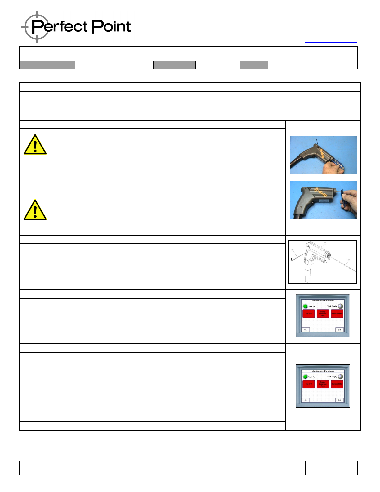
REPLACING AND SETTING THE ELECTRODE:
Electrode replacement is necessary when either:
A) The current electrode is consumed and should be replaced when indicated by a flashing green light on the hand-tool and a message on the
Hand Held Terminal, or
B) When changing to a different fastener with different stem diameter or oversize type.
EACH FASTENER SIZE AND DIAMETER, AND OVERSIZE FASTENER HAS A MATCHING ELECTRODE SIZE. WHEN
CHANGING TO A DIFFERENT STEM DIAMETER OR OVERSIZE TYPE FASTENER, THE PROPER CORRESPONDING
ELECTRODE MUST BE INSTALLED FOR SUCCESSFUL SYSTEM OPERATION.
1. Unlock the installed Adapter Tip by gripping and twisting it counter-clockwise (when viewed from the front of the e drill). Then pull the Adapter
tip straight out.
2. Unthread the existing Electrode using the Torque-Ring Wrench by inserting it over the Electrode until it engages the Electrode detents.
Remove the Electrode by turning it counter-clockwise. It may be necessary to advance the electrode: in which case, with system power on,
advance the installed electrode completely forward by depressing gun trigger until the Electrode advances fully. When you have reached the
forward limit the LED at the top of the e•drill will illuminate Red and the e•drill mechanism will stop automatically. If the electrode wont
advance, and the system is indicating that the electrode should be replaced, press the green retract button briefly before attempting to
advance the electrode.
3. Hand-thread the replacement Electrode onto the e•drill. Install the Torque-Ring Wrench by slipping it over the Electrode until it engages the
Electrode detents. Tighten the replacement Electrode with the Torque -Ring until it “breaks” (or skips) when the required torque is reached.
Remove the Torque-Ring and replace the required Adapter Tip over the Electrode.
4. Retract the Electrode by pressing and holding down the green retract button in the base of the e drill grip until the LED in the back of the
e•drill handle illuminates Green indicating the Electrode is fully retracted.