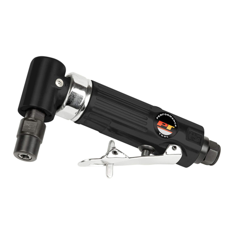
Performance Tool W50058 User manual

¤
CUS
E154499
LISTED
Maximum HP developed ...............3/4
Volts....................................................115
Hertz...................................................60
RPM ......................................................3450 (no load speed
)
GRINDING WHEEL SIZE................8"X 1"X 5/8"
GRINDING WHEEL GRIT...............36 & 60
LEFT & RIGHT TOOL RESTS
LEFT & RIGHT EYE SHIELDS AND ASSEMBLIES
LEFT & RIGHT SPARK GUARDS
PROTECT YOUR EYES.
The operation of any power tool can
result in foreign objects being thrown
into the eyes which can result in severe
eye damage. Always wear eye protection
during power tool operation.
SAFETY
GLASSES
PLEASE WEAR
FORESIGHT IS BETTER
THAN NO SIGHT
To avoid electrical shock to yourself and
damage to the bench grinder, use proper
circuit protection.
The Bench grinder is factory wired for 115V,
60 Hz operation. Connect to a 115V, 15 amp
branch circuit and use a 15 amp time delay
fuse or curcuit breaker. The electrical circuit
can not have any wire size less than #12. To
avoid shock or fire, replace power cord
immediately if it is damaged in any way.
SPECIFICATIONS
8" Bench Grinder
Stock Number W50058
OWNER’S MANUAL
TABLE OF CONTENTS
Safety Instructions .................................................................2
Bench Grinder Safety.............................................................3
Electrical Requirements.........................................................3
Replacement Parts List..........................................................4
Bench Grinder Assembly.......................................................4
Maintenance............................................................................5
Warranty ..................................................................................6

SAFETY INFORMATION
Carefully read through the entire owner’s manual before operating
your bench grinder. Keep manual with important records for safety
instructions, operating procedures and warranty.
• READ THE ENTIRE MANUAL.
• GROUND ALL TOOLS. Any tool supplied with a 3-prong plug must
be plugged into a 3-contact electrical receptacle. The 3rd prong is
used to ground the tool and provide protection against accidental
electrical shock. Never remove the third prong.
• AVOID DANGEROUS ENVIRONMENTS. Do not use power tools
near gasoline or other flammable materials, in damp or wet
locations or expose them to rain. Keep work area well lit. Normal
sparking of the motor or sparking from grinding metal could ignite
fumes.
• KEEP WORK AREA CLEAN. Messy areas and cluttered work
benches invite personal injury and or property damage.
• KEEP CHILDREN AND VISITORS AWAY. All children should be
kept away from the work area. Maintain a safe distance for any
person near the work area. Adults near the work area must wear
safety glasses. DO NOT let children handle the power tool or
extension cord.
• DRUGS, ALCOHOL, MEDICATION. Operating any tool or
equipment under the influence of drugs, alcohol, and or medication
can cause personal injury to yourself and others.
• WEAR PROPER APPAREL. Remove your jewelry before using
tool. DO NOT wear loose clothing, neckties, rings, bracelets, or
other jewelry which may get caught in moving parts. Non skid
footwear and non-electrically conductive gloves are highly
suggested while working. Wear protective hair covering to contain
long hair.
• PROTECT YOUR EYES.
The operation of any power tool can result in foreign objects being
thrown into the eyes which can result in severe eye damage.
Always wear eye protection during power tool operation.
Eyeglasses are not always safety glasses.
• BE RESPONSIBLE FOR YOUR HEARING AND BREATHING.
Wear hearing protection during extended periods of operation.
Protect your lungs by wearing a clean face or dust mask.
• GUARD AGAINST ELECTRICAL SHOCK. Avoid body contact with
grounded surfaces such as pipes, radiators, ovens, stoves and
refrigerator enclosures.
• USE THE RIGHT TOOL. Use tools properly and for its intended task.
DO NOT force a small tool to do the job of a heavy duty tool. Using the
right tool to do the right job will do the job intended and safer.
• CHECK DAMAGED PARTS. Before use of a tool, a guard or
other part that is damaged, it should be carefully checked to assure
that it will operate properly and perform its intended function. Check
for misalignment or binding of moving parts, breakage of parts,
mounting, or any other conditions that may affect its operation. A
guard or other part that is damaged should be properly replaced.
See Replacement parts list on page 4.
BEFORE USING YOUR BENCH GRINDER
WARNING: When using electrical tools, machines or
equipment, basic safety precautions should always be
followed to minimize the risk of fire, electrical shock or
personal injury to yourself and others.
• AVOID UNINTENTIONAL STARTING. Be sure that your power tool is
in the “OFF” position before plugging it into a power cord or electrical
receptacle.
• STORE ALL MAINTENANCE TOOLS away from the immediate area
prior to turning “ON” your bench grinder.
• DO NOT OVERREACH. Proper footing and balance is a must at all
times while using the tool. Unstable support may lead to personal
injury.
• DO NOT STAND ON THE TOOL. Serious injury could result if
the tool tips over or you accidentally contact the tool.
• NEVER LEAVE TOOL RUNNING UNATTENDED.
ALWAYS turn the power to the “OFF” position and do not leave the tool
until it comes to a complete stop.
• USE RECOMMENDED ACCESSORIES. Consult the owners
manual for recommended accessories. The use of
improper accessories may cause risk of injury to yourself
and others.
• ALWAYS MAKE SURE THE TOOL IS IN THE “OFF” POSITION
AND UNPLUGGED from the electrical receptacle
when making adjustments, changing parts or performing
any maintenance,
• SECURE WORK. When possible the use of clamps or a holding
device is much safer than holding the workpiece with your hands.
• KEEP PROTECTIVE GUARDS IN PLACE AND IN PROPER
WORKING CONDITION.
• MAINTAIN TOOLS WITH CARE. Tools function better and
safer when kept clean and in good working condition.
Keeping the tool clean, dry, free of grime will add to its life
and performance.
• CHILDPROOF THE WORKSHOP. The use of master switches
and padlocks is highly suggested. Remove starter keys.
• EXTENSION CORD GUIDELINES. Use only 3-wire extension cords
that have 3-prong grounding type plugs and 3 prong receptacles that
accept the tool’s plug. Only UL listed extension cords should be used
with this product. Improper use of extension cords may cause inefficient
operation of your tool which can result in overheating. Be sure your
extension cord is rated to allow sufficient flow to the motor. Refer to
guide below for minimum gauge for extension cords.
EXTENSION CORD LENGTH WIRE SIZE (A.W.G.)
Up to 25 feet 16
26 to 50 feet 16
51 to 100 feet 16
The use of an extension cord heavy enough to carry the current a tool
will draw is very important. Especially when the power source is of
great distance. A extension cord that is insufficient will cause a drop in
line voltage, resulting in power loss and causing the motor to overheat.
When the project requires you to be outdoors, use an extension cord
designed for outdoor use. The letters “WA” are indicated on the jacket
of the cord.
2


ELECTRICAL REQUIREMENTS
CONNECTING TOOL TO POWER SOURCE OUTLET
This machine source must be grounded while in use to protect the
operator from electric shock. In the event of a malfunction or
breakdown, grounding provides a path of least resistance for
electric current to reduce the risk of electric shock. This tool is
equipped with an electric cord having an equipment grounding
conductor and a grounding plug.The plug must be plugged into a
matching outlet that is properly installed and grounded in
accordance with all local codes and ordinances.
Improper connection of the equipment grounding conductor can
result in a risk of electric shock.The conductor with insulation
having an outer surface that is green (with or without yellow stripes)
is the equipment grounding conductor. If repair or replacement of
the electric cord or plug is necessary, DO NOT connect the
equipment - grounding conductor to a live terminal. DO NOT
MODIFY THE PLUG PROVIDED. If it will not fit the receptacle,
have the proper receptacle installed by a qualified electrician.
Check with a qualified electrician or service personnel if the
grounding instructions are not completely understood, or if in doubt
as to if the tool is properly grounded.
Fig. A
BENCH GRINDER SAFETY
PROTECT YOUR EYES.
The operation of any power tool can result in foreign objects
being thrown into the eyes which can result in severe eye
damage. Always wear eye protection during power tool
operation.
SAFETY
GLASSES
PLEASE WEAR
FORESIGHT IS BETTER
THAN NO SIGHT
USE THE WHEEL GUARDS AND SAFETY EYE SHIELDS that
are provided with your bench grinder.
USE ONLY GRINDING WHEELS that are rated at higher RPM
than the maximum RPM of your bench grinder.
CRACKED OR DAMAGED GRINDING WHEELS. Replace
immediately cracked or damaged grinding wheels that can give
out debris at a high speed. Handle the grinding wheel carefully
since they are abrasive. Check the replacement wheel for cracks
prior to installing. DO NOT remove the label or blotter on both
sides of the grinding wheel. The spindle nut should be tightened just
enough to hold the wheel firmly to your bench grinder. It is possible to
damage the grinding wheel with too much clamping force.
DO NOT use the bench grinder if the flange nut or clamp nut is
missing or if the spindle shaft is bent.
GRINDING WHEELS will get smaller with use. The distance
between the work rest and wheel must be periodically adjusted to 1/16”.
DO NOT START GRINDER when the grinding wheel is in contact
with the workpiece.
GENTLY apply the workpiece against the grinding wheel when
starting your project. A sudden impact can damage the wheel. The
use of slight pressure is best when starting to grind. The use of
too much pressure too quickly on a cold wheel can cause damage
to the wheel.
This tool is intended for use on a circuit that has an outlet that looks
like the one illustrated in Figure A. The tool has a grounding plug
that looks like the one also shown in Figure A. DO NOT modify the
plug provided if it will not fit the outlet. Have the proper outlet
installed by a professional electrician.
WARNING: If not properly grounded, this power tool can
incur the potential hazard of electrical shock particularly
when used in damp locations or in proximity to plumbing. If
an electrical shock occurs, there is the potential of a
secondary hazard such as your hands contacting the
grinder tool.
DO NOT STAND directly in front of the bench grinder when
starting. When turning the bench grinder to the “ON” position,
stand to one side. There is always the possibility of debris
discharged toward the operator.
INSPECT TOOL CORDS AND EXTENSION CORDS. If
damaged, have repaired or replaced immediately. Know their
location, keep them well away from the grinding wheel.
BENCH GRINDERS will emit sparks and produce debris. DO
NOT use power tools where flammable gas or liquids exist. Clean
your bench grinder and area of grinding dust.
KEEP IN MIND. Stay alert and aware of what you are doing.The
slightest mistake can cause personal injury and or property damage.
YOUR BENCH GRINDER MUST be securely mounted to a
suitable workspace before operating. (hardware not included)
PLAN YOUR PROJECT. Avoid awkward operations and hand
positions where a sudden slip could cause personal injury. Hold
the workpiece firmly and keep body parts a safe distance from
grinding wheels.
WHEEL GUARDS, KEEP THEM IN PLACE. DO NOT operate the
bench grinder with the wheel guards removed.
KEEP TOOL RESTS FIRMLY TIGHTENED.
3
WARNING: Some dust created by grinding and other
construction activities contains chemicals known to
cause cancer, birth defects or other reproductive
harm. Some examples of these chemicals are: LEAD
from lead based paint, CRYSTALLINE SILICA from
bricks and cement and other masonry products,
ARSENIC and CHROMIUM from chemically treated
lumber. Your risk from these exposures varies,
depending on how often you do this type of work. To
reduce your exposure to these chemicals: work in a
well ventilated area, and work with approved safety
equipment, such as those dust masks that are
especially designed to filter out microscopic particles.

INSTALLING TOOL RESTS
Remove the tool rests from the
package and install them to the
wheel guards as shown in Figure 1.
Use the bolts and washers to secure
them in place.
Note: There is a left and right tool
rest. Refer to Figure 1 to ensure that
you install them correctly.
When in actual use, the tool rests
should be adjusted to within 1/16”
of the grinding wheel.
INSTALLING THE SPARK GUARDS
Select the two spark guards and the
two smaller bolts and washers. Install
the spark guards to the wheel guards
of your grinder as shown in Figure 2.
Adjust them to within 1/16” of the
grinding wheel.
Note: There is a left and right spark
guard. Refer to Figure 2 to ensure
that you install them correctly.
INSTALLING THE EYE SHIELDS
Note: There is a left and right eye shield mounting rod. Examine Figure 3
to ensure that you install them correctly. The one pictured in Figure 3 is for
the right wheel guard as you face the front of the tool. Assemble one
mounting rod, one bracket, one bolt as shown and install it to the wheel
guard of the grinder. Position it with the arm high, as shown in Figure 4,
and tighten the bolt securely.
Note: The eye shields are identical and will fit properly on either side of the
grinder. However it may be necessary to loosen the center hex nut in order
to slip the shield over the mounting rod.
After you have installed each eye shield mounting rod to the grinder, attach
the eye shields to the rods, as shown
in Figure 5. Install them in such a
way that the three hex nuts on each
eye shield are on the back side,
away from the operator when the
tool is in use.
Tighten the center hex nut so that
the shield can be moved but will be
tight enough to stay in place.
ALWAYS position the eye shields
between your eyes and the grinding
wheel.
BENCH GRINDER ASSEMBLY
LOOSE PARTS CONTENTS:
Tool Rest.............................................................................. 2 each
Mounting rods...................................................................... 2 each
Eye Shields.......................................................................... 2 each
Brackets ............................................................................... 2 each
Spark Guard ........................................................................ 2 each
3/4” Bolts ............................................................................. 2 each
1/2” Bolts ............................................................................. 4 each
5/8” Bolts.............................................................................. 2 each
Large Washers .................................................................... 6 each
Washers............................................................................... 2 each
The following tools (not included) are needed for assembly and
alignment: 8, 10, and 12mm Combination wrench, Phillips
screwdriver, Adjustable wrench
WARNING: If any parts are missing DO NOT operate this
machine until the missing parts are replaced. Failure to do
so could result in possible serious injury.If parts are missing,
contact customer service at 1-800-497-0552.
DO NOT begin assembly of your bench grinder until you are certain
the tool is NOT plugged in.
DO NOT begin assembly until you are certain the bench grinder is in
the “OFF “ position.
DO NOT begin assembly until you are certain that the grinding wheels
are securely tightened to your bench grinder.
1. Inspection- To be certain the grinding wheels have not been
damaged in shipment, inspect carefully. If you suspect a wheel of
being fractured, REPLACE IMMEDIATELY. Fractured wheels may
shatter causing serious injury or property damage.
2. Mount bench grinder (hardware not included) on a firm level
surface where there is plenty of room for handling and properly
supporting the workpiece. Keep in mind the nearest electrical
receptacle.
3. Avoid a dangerous environment. Use the grinder in a dry, indoor
place protected from the rain. Keep work area well lit.
4. Disconnect tools before servicing or when changing accessories
such as grinding wheel.
5. Keep guards in place and in working order. To avoid accidental
starting, make sure the power switch is in the “OFF” position before
plugging in.
6. Use recommended accessories. Consult the owners manual for
recommended accessories. The use of improper accessories may
cause risk of injury to yourself and others.
WASHERS
SHORT
BOLTS
RIGHT
TOOL
REST
LONG
BOLT
BRACKET
RIGHT
MOUNTING
ROD
EYE SHIELD
MOUNTING ROD
ASSEMBLY
RIGHT
MOUNTING ROD HEX
NUT
BACK OF
EYE SHIELD
RIGHT
SPARK
GUARD
BOLT
WA SHER
4
Fig. 5
Fig. 4
Fig. 3
Fig. 2
Fig. 1

WARNING: For your own safety, turn switch “OFF” and remove
plug from power source outlet before adjusting and maintaining
your bench grinder. If power cord is worn, cut, or damaged in
any way, have it replaced immediately.
CARE FOR GRINDING WHEELS
In normal use, grinding wheels may become cracked, grooved,
rounded at the edges, chipped, out of true or loaded with foreign
material. Cracked wheels should be replaced IMMEDIATELY.
WHEEL REPLACEMENT
If you must replace a wheel, be sure to obtain one with a safe rated
speed as high as the RPM marked on your grinders nameplate and
with a 5/8” center hole. A 8” diameter wheel should be a maximum of 1”
wide. Check new wheels for cracks and maintain the existing sequence
of retaining hardware. Be sure the tool is unplugged before attempting
repairs.Your bench grinder will accept most polishing and buffing
wheels.
To replace the grinding wheel:
1. Turn the power switch to “OFF” and unplug the power cord from the
power source.
2. Move eyeshields to “UP” position for easy access to the tool rests.
3. Remove the wheel cover by loosening the 3 screws holding the wheel
cover to the bench grinder.
4. Using a small wooden wedge, place it between the abrasive wheel and
the tool rest to prevent the wheel from turning.
5. With a 3/4” wrench, loosen the wheel nut in a clockwise direction for
the left side and a counterclockwise direction for the right side.
6. Remove the outer flange and grinding wheel from the arbor shaft.
7. Replace with grinding wheels that are rated at a higher RPM rating than
the bench grinder.
NOTE: DO NOT remove the label on the side of the abrasive wheel. Be
sure the grinding wheel and both flanges are properly seated on the
spindle shaft.
8. To install a new grinding wheel, reverse the removal procedure.
NOTE: DO NOT over tighten the lock nut as this may cause damage to the
grinding wheel and may cause personal injury to the operator.
MAINTENANCE
STAR
WASHER
SPINDLE
SHAFT
OUTER
FLANGE
SCREW(S)
WHEEL
GUARD COVER WHEEL
NUT GRINDING
WHEEL
INNER
FLANGE
HEX NUT(S)
8” Bench Grinder
OFF ON
CLEAN your bench grinder only after the power switch is in the
“OFF” position and unplugged from the power source. Turn the
grinding wheels slowly and inspect for damaged or trapped debris
and dust build up. Use a clean dry rag or brush to remove debris
or dust build up.
NEVER use flammable materials to clean bench grinder.
NO LUBRICATION is required. Your bench grinder has sealed
lubrication bearings in the motor housing.
WARNING: The use of any other accessories is not
recommended and may result in serious injury.
PROTECT YOUR EYES.
The operation of any power tool can result in foreign objects being
thrown into the eyes which can result in severe eye damage. Always
wear eye protection during power tool operation.
SAFETY
GLASSES
PLEASE WEAR
FORESIGHT IS BETTER
THAN NO SIGHT
5

OFF
ON
8” Bench Grinder
Performance
Tool
®
1
2
3
4
5
6
7
8
9
10B
11
12
13
14 15
10A
1 YEAR LIMITED WARRANTY
PERFORMANCE TOOL extends only the following warranties, and only to original retail purchasers.These warranties give specific legal rights. Except where prohibited by local law, the law of
the State of Washington governs all warranties and all exclusions and limitations of warranties and remedies. There may be other rights which vary from state to state.
PERFORMANCE TOOL warrants the product to be free from defects in materials and workmanship under normal use and service. A defective product may be returned for a free replacement
within 1 year from the date of purchase, provided that product is returned to place of purchase immediately after discovery of defect. These warranties shall be valid only when a sales receipt
showing the date of purchase accompanies the defective product being returned.
These warranties exclude blades, bits, punches, bulbs, fuses, grinding wheels, and other consumables which must be replaced under normal use and service.These warranties shall not apply
to any product or part which is used for a purpose for which it is not designed, or which has been repaired or altered in any way so as to affect adversely its performance or reliability, nor shall
these warranties apply to any product or part which has been subject to misuse, neglect, accident or wear and tear incident to normal use and service.
PERFORMANCE TOOL does not authorize any other person to make any warranty or to assume any liability in connection with its products.
Except for warranties of title and the limited express warranties set forth above, PERFORMANCE TOOL makes no express or implied warranties of any kind with respect to its products. In
particular, PERFORMANCE TOOL makes no implied warranty of merchantability and no implied warranty of fitness for any particular purpose, except that for goods purchased primarily for
personal, family or household use and not for commercial or business use, PERFORMANCE TOOL makes an implied warranty of merchantability (and, if otherwise applicable, an implied
warranty of fitness for a particular purpose), but only for the particular qualities or characteristics, and for the duration, expressly warranted above. The laws on limitation of implied warranties
may differ from state to state, so the above limitations may not apply in all cases.
PERFORMANCE TOOL shall not be liable for consequential, incidental or special damages resulting from or in any manner related to any product, or to the design, use, or any inability to use
the product. The sole and exclusive remedy for a defective product or part shall be the repair, or replacement thereof as provided above.The laws on limitation of remedies or on consequential,
incidental or special damages may vary from state to state, so the above limitations may not apply in all cases.
Copyright © 2002 PERFORMANCE TOOL P.O. Box 88259 Tukwila, WA 98138 – All rights reserved
1. WHEEL GUARD - Covers the grinding wheels
and protects against accidental contact.
2. WHEEL COVER - Covers the grinding wheels
and provides access for routine maintenance.
3. MOTOR HOUSING - Contains the electrical motor.
4. MOUNTING FEET - Helps to minimize vibration of the grinder.
5. EYE SHIELD MOUNTS - Supports the eyeshields.
6. EYE SHIELDS - Protective see through shields prevent any
loose debris from contacting the operator.
7. SPARK GUARDS - Prevents hot sparks and debris from
contacting the operator.
8. TOOL REST SUPPORT - Lets the operator position the tool
rest closer to the wheel as the wheel decreases in diameter due
to wear.
9. TOOL RESTS - Used to support the workpiece that is being
ground.
10A. 8"GRINDING WHEEL 60 GRIT - Used to remove light
material from a workpiece.
10B. 8"GRINDING WHEEL 36 GRIT - Used to remove heavy
material from a workpiece.
11. ON / OFF SWITCH - Used to turn “ON” and turn “OFF” the
grinder.
12. MOUNTING PAD - Used to secure grinder to a workbench or
other suitable work surface.
13. GRINDING WHEEL IDENTIFICATION LABEL - Provides
information on the wheel size, grit and maximum rpm. Must be
left on to distribute the load of tightening the lock nuts.
14. FLANGES - Used to secure the grinding wheels to the grinder
and distribute the load of the lock nuts.
15. LOCK NUT - Used to secure the grinding wheels to the grinder.
WARRANTY
Table of contents
Other Performance Tool Grinder manuals

Performance Tool
Performance Tool M656 User manual

Performance Tool
Performance Tool W50044 User manual

Performance Tool
Performance Tool M547 User manual

Performance Tool
Performance Tool M566DB User manual

Performance Tool
Performance Tool W50003 User manual

Performance Tool
Performance Tool M658 User manual

Performance Tool
Performance Tool W50001 User manual