Defrost System - Hot Gas Defrost
This system consists of a six-hour, as well as a
four-hour defrost cycle which includes a 20 minute
evaporator defrost. The six-hour defrost cycle is
manually activated and automatically terminated,
while the four-hour cycle is completely automatic.
■ The Six Hour Solid-State Defrost Timer:
This timer shuts off the power to the
condensing unit, the evaporator fan, and
the automatic four hour defrost timer.
To activate the six hour defrost system,
depress the defrost switch located on the
front grille of the cabinet. An amber light will
illuminate and the defrost cycle will begin.
When the defrost cycle ends, the light
goes off and the cabinet resumes normal
operation. To manually cancel the defrost
cycle, momentarily turn off the electricity to
the unit.
■ The Four Hour Defrost Timer:
This timer ensures that frost will not buildup on
the evaporator coil. Every four hours the hot gas
by-pass valve is opened and hot gas is
circulated through the evaporator coil. The
defrost is terminated when the coil is clear of
frost. The defrost cycle lasts for approximately
20 minutes.
During normal operation it is recommended that
the doors are not left open to prevent excessive
frost buildup on the coil.
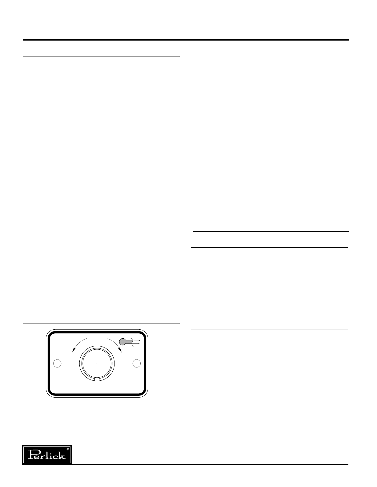
Temperature Control
An adjustable temperature control is located inside
the freezer on the evaporator fan panel
assembly. Approximate temperature operating
range: minus 15° F. minimum and plus 10°F
maximum. Make adjustments as shown to attain
the desired temperature.
■ Colder Temperatures: Turn the adjusting
screw clockwise (to the right).
■ Warmer Temperatures: Turn the adjusting
screw counterclockwise (to the left).
■ Temperature Control “OFF”: Turn the
adjusting screw completely counterclock-
wise to the “O” position until a click is noted.
The condenser fan and the evaporator fan motor
turns off and on with the compressor.
Cleaning the Condenser
■ The Condenser (located behind the front
grille) should be inspected every 30 days,
and cleaned, if necessary. Failure to keep
the condenser clean will cause a loss in
condensing unit efficiency, or compressor
failure.
CAUTION: Do not bend the fins while
brushing the front of the condenser.
Cleaning the Cabinet
■ Use a damp cloth and a mild detergent and
water to clean the inside and outside of the
cabinet. Dry thoroughly. Do not allow cleaning
agents or large amounts of water to go down
the drain. Uae an acceptable stainless steel
polish to clean all stainless steel surfaces.
Never use steel wool, scouring pad or abrasive
cleanser.
NOTE: An industrial strength, commercial
cleaner can be used to clean the outside of
painted cabinets
NORMAL
05
4
6
1
9
2
8
3
7
WARMER
COOLER
CONDENSING UNIT
4
Perlick is committed to continuous improvement. Therefore, we reserve the right to change specifications without prior notice.
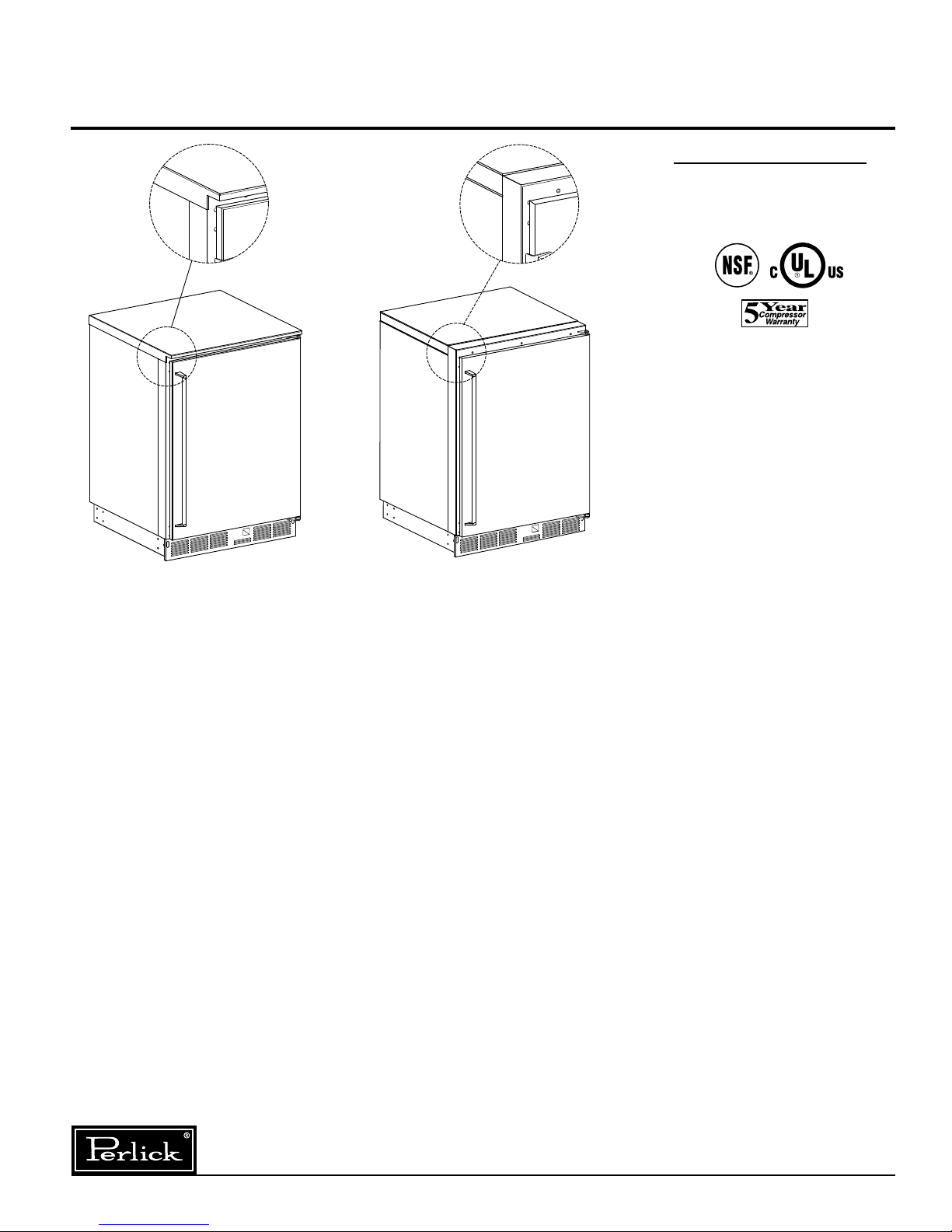
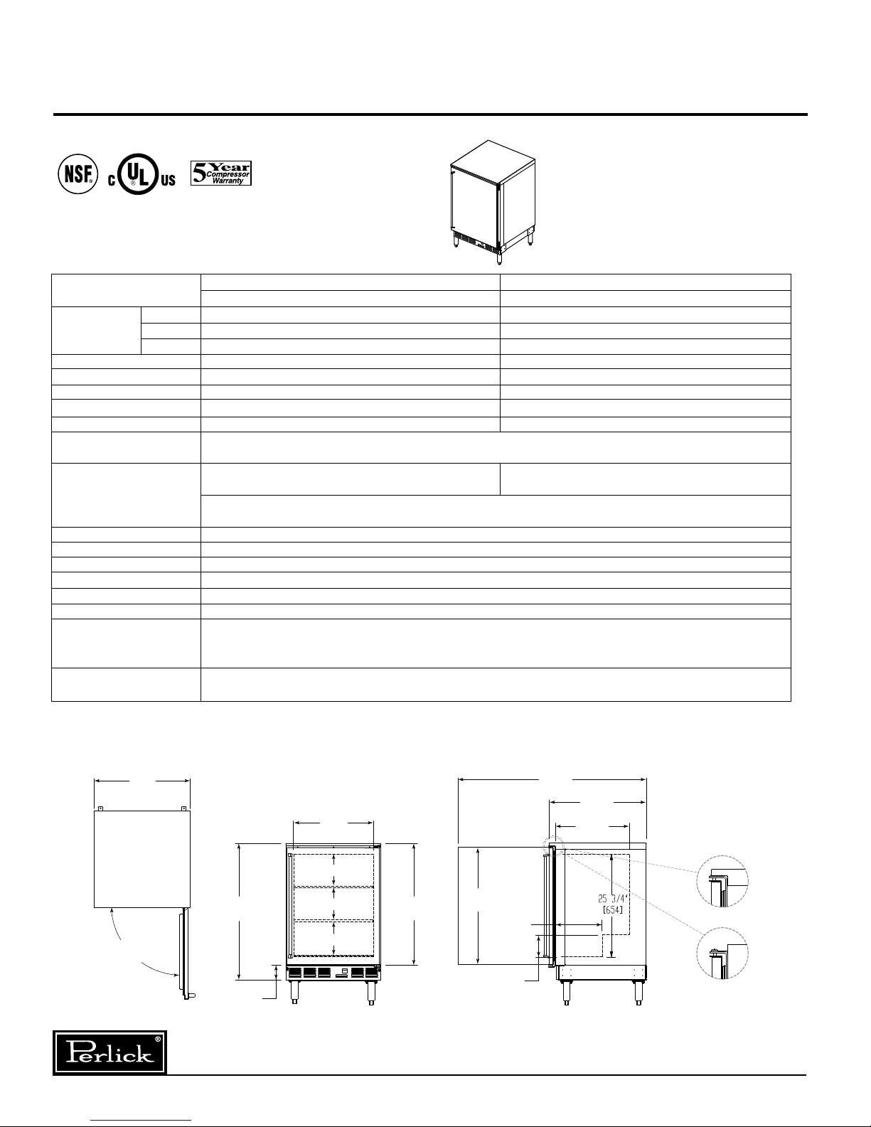
Operation Instructions – Single Door Freezer
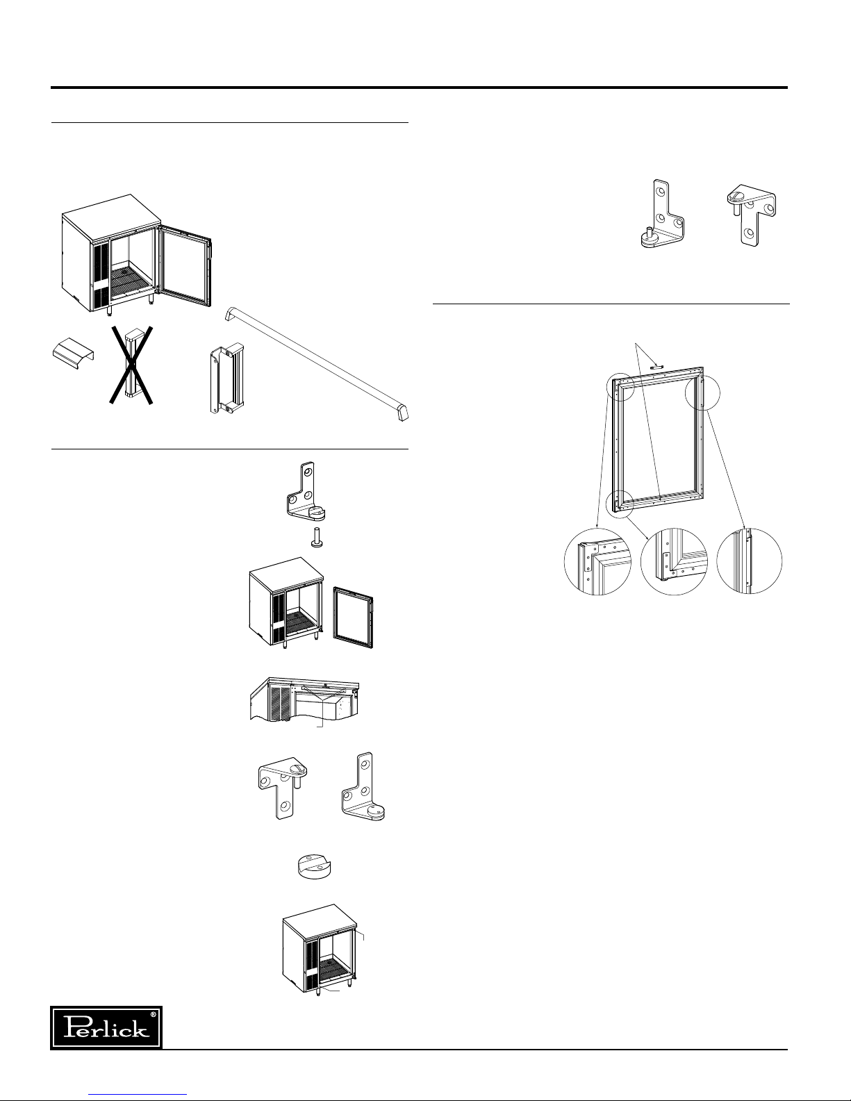
Cleaning Instructions –
Single Door Freezer
Form No. Z2255
Rev. 01.04.09