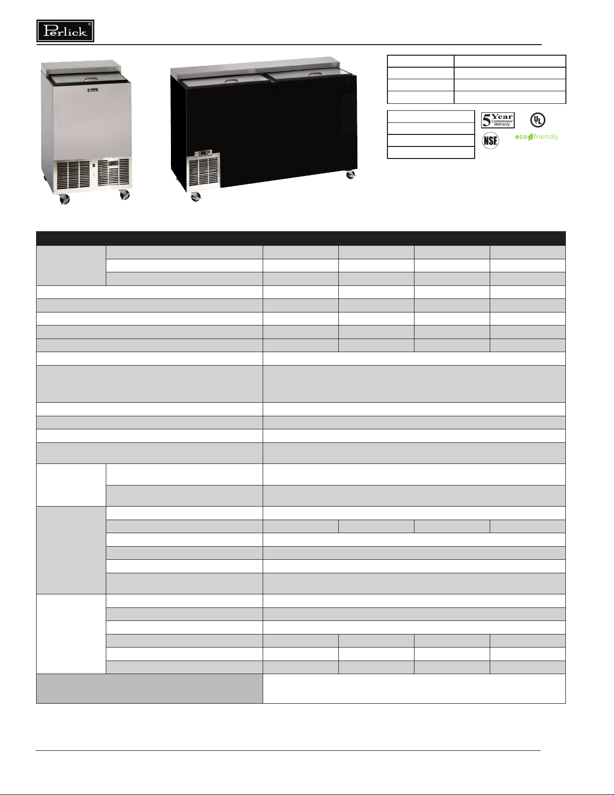
Glass Frosters Installation & Operation Manual
Printed in USA 4
Perlick is committed to continuous improvement. Therefore, we reserve the right to change specications without prior notice.
PREPARING THE CABINET -GLASS FROSTERS
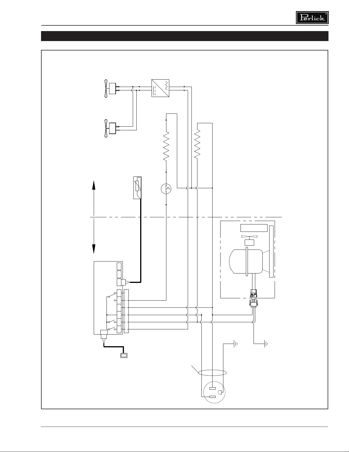
Refrigerant
All models covered in this user manual are
manufactured using refrigerant R290 (Propane).
R290 is a hydrocarbon. This refrigerant is
ammable and is only allowed for use in
appliances which fulll the requirements of UL
471 (To cover potential risk originated from the
use of ammable refrigerants). Consequently,
R290 is only allowed to be used in refrigerating
appliances which are designed for this
refrigerant and fulll the above-mentioned
standard.
■ R290 is heavier than air. The concentration
will always be highest at oor level.
■ The explosion limits are as follows:
- Lower Limit: 1.7% by vol. (37 g/m3)
- Upper Limit: 9.5% by vol. (177 g/m3)
- Ignition Temperature: 470 °C
Take caution when handling,
moving and using the
product to avoid damaging the refrigerant
tubing or increasing the risk of a leak.
All service work shall
be performed by factory
authorized service personnel and all
component parts shall be replaced with like
components to minimize the risk of possible
ignition due to incorrect parts or improper
service.
If service is necessary,
repair work must be performed by a
Perlick authorized servicer. Work done by
unqualied individuals could potentially be
dangerous and will void the warranty.
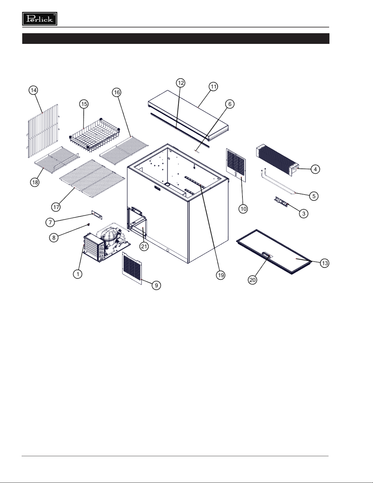
Uncrating and Inspection
Remove all crating material. Carefully inspect
cabinet for hidden damage. If damage is
discovered, le your claim immediately with the
transport company. Perlick is not responsible for
damage in transit.
Plumbing
No plumbing connections are required.
Condensate from the cooling coil automatically
evaporated through a condensate pan located in
the condensing unit section.
Electrical
The cabinet must be connected to a separately
fused power source (see Electrical Specication
Plate axed to unit) in accordance with National
and Local electrical codes.
Do not attempt to operate
the equipment on any
other power source than that listed on the
Electrical Specication Plate.
Adjustable Partitions & Shelving
Perlick Glass Frosters may be provided with
adjustable partitions and shelving which will
accommodate various bottle sizes.
■ When placing glasses in
chiller make sure to ensure proper
air ow between glasses.
■ When loading product into cabinet, care must
be taken to avoid blocking airow into and out
of the evaporator. Maintain at least 2” of
clearance on evaporator air intake and
exhaust for proper operation.
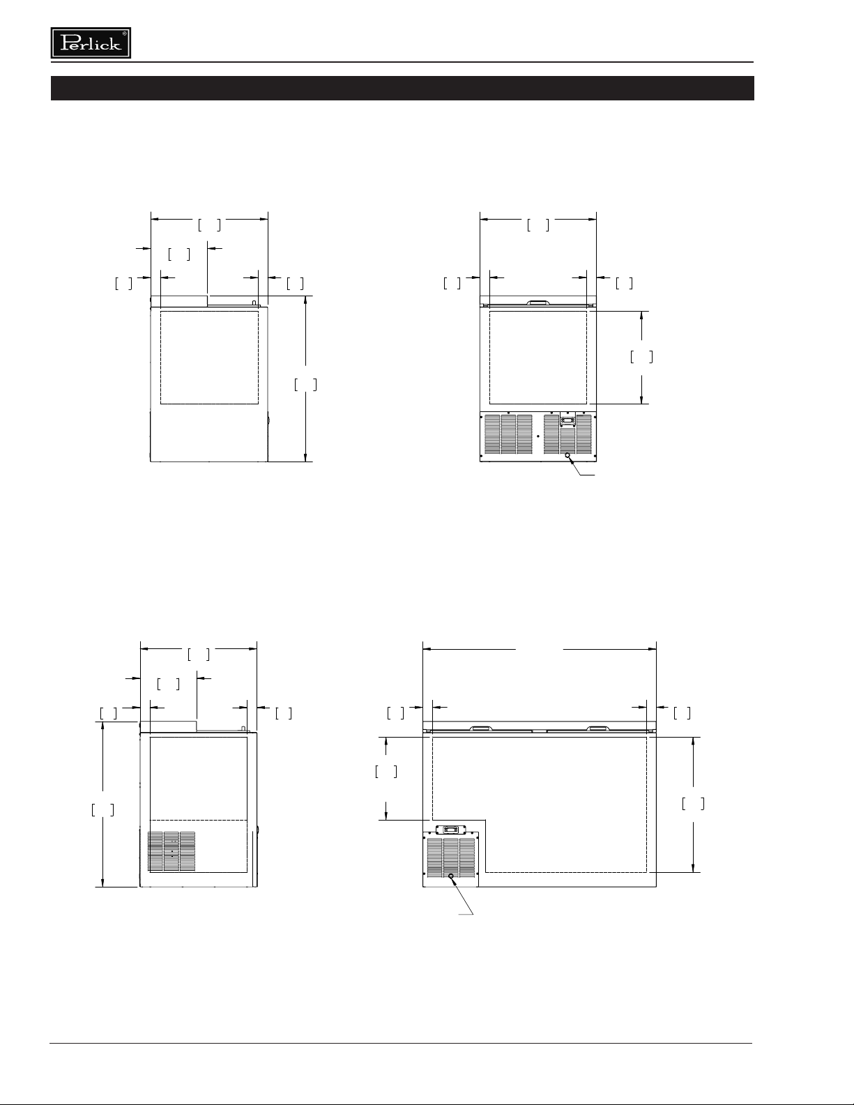
Installing Casters or Legs (optional)
Attach casters or legs to the cabinet bottom in
holes provided. Use the supplied 1/4” - 20 hex
head self-tapping machine screws. If unit is tipped
on its back, wait 24 hours after unit is uprighted
to plug the unit in.
Placing the Cabinet
To assure maximum performance, fresh air must
be allowed to circulate through the machinery
compartment. It is important to allow at least
two inches of clearance at the back or left end
of the cabinet. Do not place anything in front of
the cabinet that would obstruct air ow at these
grilles. Do not place the unit in an unventilated
small room.
Removing the factory
installed back clearance
spacers without providing proper left side grill
clearance for compressor air ow will void the
warranty.