Perma Pure M325 User manual

P
PE
ER
RM
MA
A
P
PU
UR
RE
E
Perma Pure LLC Tel: 732-244-0010
8 Executive Dr, PO Box 2105 Tel: 800-337-3762 (toll free US)
Toms River, NJ 08754 Fax: 732-244-8140
www.permapure.com Email: [email protected]
INSTRUCTION MANUAL
THERMO-ELECTRIC COOLERS
MODULAR SERIES
Model M325

TABLE OF CONTENTS
Table of Contents 2
A: Specifications................................................................................................................ 3
B: Limited Warranty........................................................................................................... 4
C: Principle of Operation................................................................................................... 5
D: Installation .................................................................................................................... 7
E: Start-up Procedure ....................................................................................................... 8
F: LED Indicators ..............................................................................................................9
G: I/O Terminal Block Description................................................................................... 10
H: Test & Adjustment Procedures................................................................................... 11
I: Description of Options.................................................................................................. 14
J: “New Jersey” Thermocouple Option............................................................................ 15
K: Troubleshooting .......................................................................................................... 16
L: Spare Parts .................................................................................................................17
Appendix A: Model M325 ................................................................................................ 19
Appendix B: Sample Conditioning System...................................................................... 20

Section A: Specifications 3
A: SPECIFICATIONS
Physical Description
Single (Series) / Dual (Parallel) Channel System
2 x 5” Heat Exchangers connected in series or parallel
1 Passive (cooled to ambient), 1 Active (cooled to 4qC) Heat Exchangers
LCD temperature display
Operating Specifications
Sample Gas Flow Range 2-4 LPM
4.3-8.6 SCFH
Inlet Dew Point at Rated
Flow
168qF @ 40% H2O, 4 LPM
76qC
Maximum Cooling Rate 222 BTU/Hr
234kJ/Hr
Dimensions 11.20 x 7.25 x 11.20 in. HWD
28.5 x 18.4 x 28.5 cm
Weight 17 lbs
7.7 kg
Maximum Inlet Sample
Temperature
392qF (200qC) SS, Glass
Impingers
280qF (138qC) Kynar Impinger
Maximum Inlet Pressure 45 psig
3 bar / 2250 mmHg
Maximum Heat Exchanger
Pressure Drop
<+1 in. H2O
Ambient Temperature
Range
33-104qF
0.56-40qC
Outlet Sample Gas Dew
Point
41qF
5qC
Inlet Tubing Connection in. FPT
Outlet Tubing Connection ¼ in. FPT
Drain Tubing Connection in. FPT
Voltage 110 (220 optional) VAC
50/60 Hz
Thermoelectric Elements 40 mm
Power Supply 100W
Cooling Down Time Less than 3 minutes

Section B: Limited Warranty 4
B: LIMITED WARRANTY
Perma Pure LLC
WARRANTY and DISCLAIMERS
Perma Pure (Seller) warrants that product supplied hereunder shall, at the time of delivery to Buyer,
conform to the published specifications of Seller and be free from defects in material and
workmanship under normal use and service. Seller’s sole obligation and liability under this warranty is
limited to the repair or replacement at its factory, at Seller’s option, of any such product which proves
defective within one year after the date of original shipment from seller’s factory (or for a normal
usable lifetime if the product is a disposable or expendable item) and is found to be defective in
material or workmanship by Seller’s inspection.
Buyer agrees that (1) any technical advice, information, suggestions, or recommendations given to
Buyer by Seller or any representative of Seller with respect to the product or the suitability or
desirability of the product for an particular use or application are based solely on the general
knowledge of Seller, are intended for information guidance only, and do not constitute any
representation or warranty by Seller that the product shall in fact be suitable or desirable for any
particular use or application; (2) Buyer takes sole responsibility for the use and applications to which
the product is put and Buyer shall conduct all testing and analysis necessary to validate the use and
application to which Buyer puts the product for which Buyer may recommend the use or application of
the product by others; and (3) the characteristics, specifications, and/or properties of the product may
be affected by the processing, treatment, handling, and/or manufacturing of the product by Buyer or
others and Seller takes no responsibility for he nature or consequence of such operations or as to the
suitability of the product for the purposes intended to be used by Buyer or others after being
subjected to such operations.
SELLER MAKES NO OTHER WARRANTY, EXPRESS OR IMPLIED, OF THE PRODUCT
SUPPLIED HEREUNDER, INCLUDING, WITHOUT LIMITATION, IMPLIED WARRANTIES OF
MERCHANTABILITY AND FITNESS FOR PARTICULAR PURPOSE, AND ALL SUCH
WARRANTIES ARE HEREBY EXPRESSLY EXCLUDED. SELLER SHALL HAVE NO LIABILITY
FOR LOSS OF PROFITS, OR SPECIAL, INCIDENTAL, OR CONSEQUENTIAL DAMAGES UNDER
ANY CIRCUMSTANCES OR LEGAL THEORY, WHETHER BASED ON NEGLIGENCE, BREACH
OF WARRANTY, STRICT LIABILITY, TORT, CONTRACT, OR OTHERWISE. SELLER SHALL IN
NO EVENT BE LIABLE IN RESPECT OF THIS ORDER AND OR PRODUCT DELIVERED ON
ACCOUNT OF THIS ORDER FOR ANY AMOUNT GREATER THAN THAT PAID TO SELLER ON
ACCOUNT OF THIS ORDER.

Section C: Principle of Operation 5
C: PRINCIPLE OF OPERATION
Thank you for purchasing a Perma Pure Baldwin™-Series Thermo-Electric Cooler. This
Modular Series features a unique slim design leaving additional space to install or access
other sample conditioning system components. A unique drop-down door on the Modular
Series provides easy access to electronic boards and the power supply. All electronic
boards (control, relay, and display) are mounted on the door for easy access.
The process of sampling combustion product stack gas or exhaust from internal combustion
engines requires a method to remove the moisture from the sample, without removing the
gas components of interest. The Baldwin-Series cooler is an ideal way to decrease the dew
point of combustion gases to a repeatable, stable, constant low dewpoint. The Baldwin
cooler prevents water condensation in sample pre-filters, sample pumps, and gas analyzers.
For gas analyzers where water vapor is an interferant, a stable, repeatable dewpoint
becomes a part of the gas analyzer performance specification. Baldwin-Series coolers
provide this constant low water concentration, resulting in an accurate component gas
measurement.
All Baldwin-Series coolers use thermo-electric elements (Peltiers) to cool the sample gas to
the desired dew point temperature. A thermo-electric cooler is best illustrated as a small
heat pump with no moving parts. The Peltiers operate on direct current and may be used
for heating or cooling by reversing
the direction of current flow. This
is achieved by moving heat from
one side of the module to the
other with current flow and the
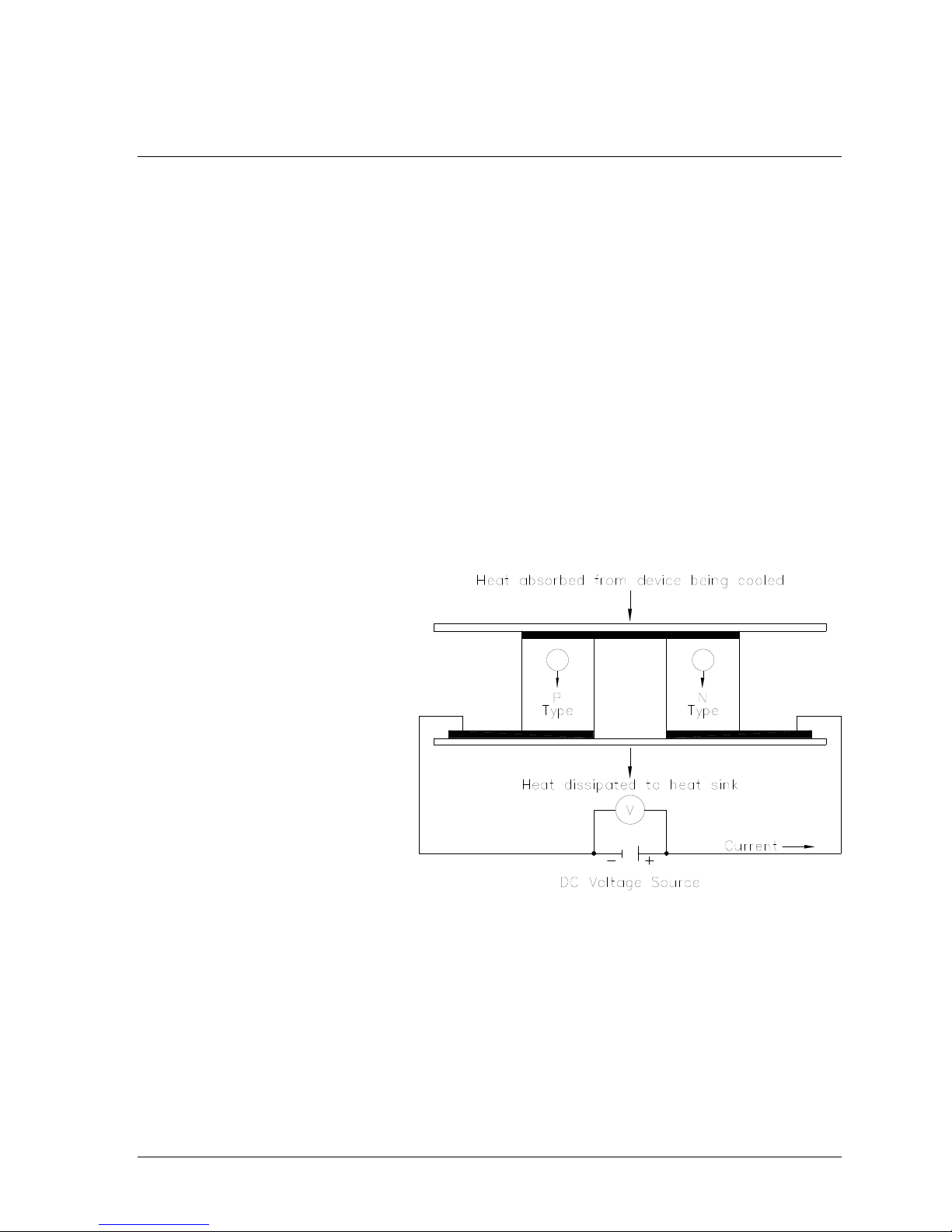
laws of thermodynamics. A typical
single stage Peltier (Figure 1)
consists of two ceramic plates with
p- and n-type semiconductor
material (bismuth telluride)
between the plates. The elements
of semiconductor material are
connected electrically in series
and thermally in parallel.
When a positive DC voltage is
applied to the n-type thermo-
electric element, electrons pass from
the p- to the n-type thermo-electric
element and the cold side temperature will decrease as heat is absorbed. The heat
absorption (cooling) is proportional to the current and the number of thermo-electric
elements. This heat is transferred to the hot side of the Peltier element where it is
dissipated into the heat sink and surrounding environment.
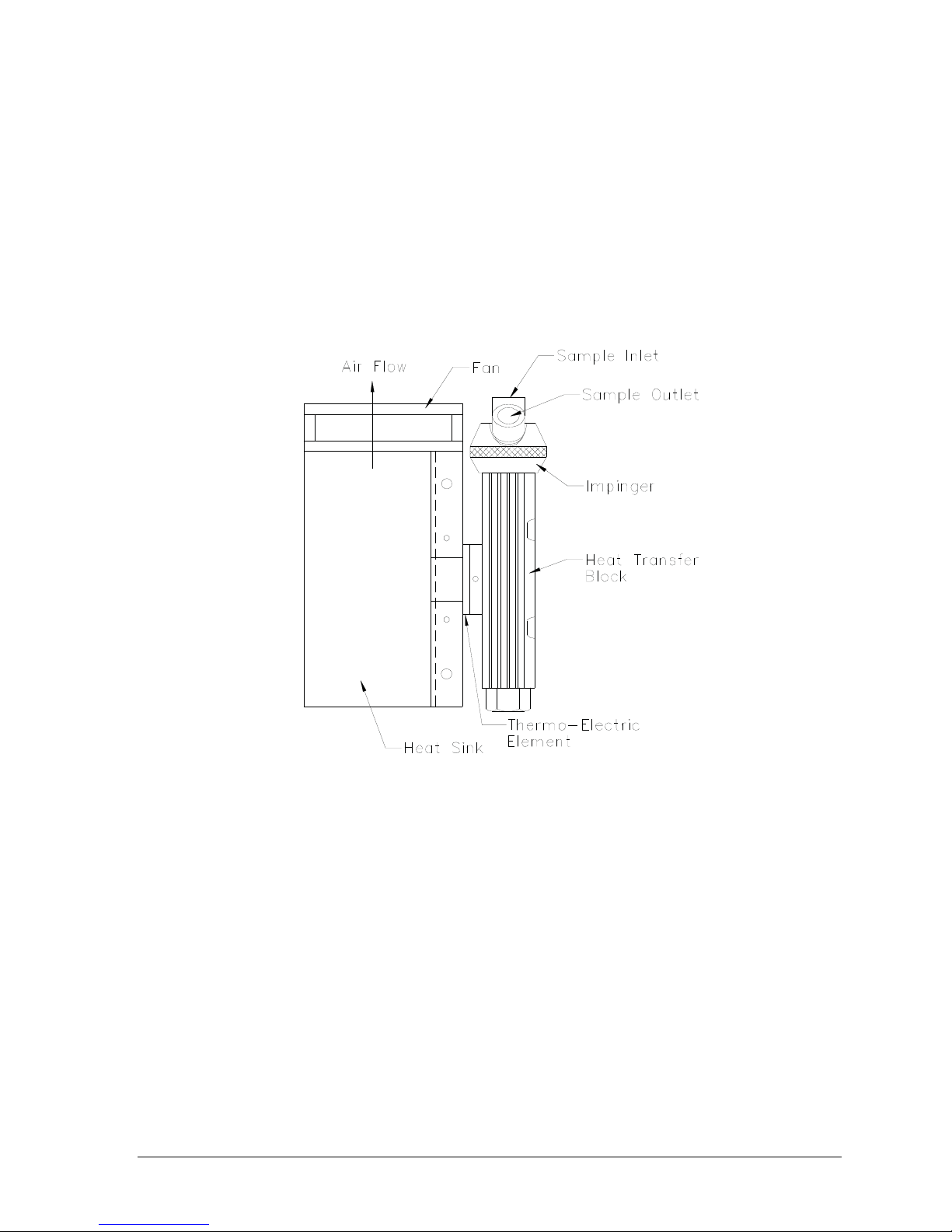
Baldwin-Series Thermo-Electric Coolers remove the moisture from the sample gas by
cooling the gas as it passes through a laminar impinger (heat exchanger). A diagram
showing the gas flow path through an impinger is shown in the Appendix. The heat
exchanger, made of 316L stainless steel, Durinert® (a corrosion-resistant inert coating over
Fi
g
ure 1: Thermo
-
electric element
(
Peltier
)

Section C: Principle of Operation 6
Fi
g
ure 2: Heat Exchan
g
er, Im
p
in
g
er and Heat Sink Assembl
y
316L stainless steel), PVDF (Kynar), or glass, is mounted within a thermally insulated heat
transfer block bored to receive the heat exchanger without a mechanical lock. This
assembly allows the easy removal of any heat exchanger simply by slipping it out of the
cooling block by hand. The heat transfer block cools the heat exchanger through the heat
pumping action of the peltier element. The heat transfer block is on the cold side of the
thermo-electric element and the heat sink is on the hot side of the thermo-electric element.
The heat from the heat transfer block is pumped to the heat sink where it is then dissipated
into the air by the heat sink fan. See Figure 2. The desired temperature is maintained by a
closed loop control system, which is implemented through an analog proportional controller.
The controller uses a type K thermocouple in the heat transfer block located very close to
the cold side of the peltier element as the input sensor.
The sample gas is passed to the thermo-electric cooler via the heated filter sample probe
and heated sample line. The thermo-electric cooler lowers the sample dew point to 5qC
(41°F). As the gas cools and the moisture vapor condenses, the condensate exits the heat
exchanger through the bottom drain connection. Particulate matter passing through the
sample cooler is removed by an optional Perma Pure pre-filter, located downstream from the
cooler along with an optional water slip sensor. The conditioned sample gas can then be
directed to the gas analyzers.

Section D: Installation 7
D: INSTALLATION
The Model M325 should be installed away from heat sources in a well ventilated
area of an instrument rack or enclosure. The more stable the ambient temperature
environment around the Model M325, the better the output dew point stability.
Sample tubing connections to the Model M325 depend on the heat exchanger
material of construction. A cooler with a stainless steel heat exchanger uses a
stainless steel inlet fitting. The outlet is Kynar®standard compression type tube
fitting with Teflon®ferrules. A PVDF (Kynar®) heat exchanger uses Kynar®standard
compression type tube fittings with Teflon®ferrules. Baldwin cannot warrantee
against damage to the Peltier element or heat exchanger if our supplied Kynar®tube
fittings are not used.
The inlet and outlet tubing for all metal or Kynar heat exchangers is 1/4" NPT; the
user should always use the compression type fittings provided for that purpose by
the factory. The inlet of the Channel 1 heat exchanger uses a 3/8” tube x ¼” MNPT
fitting to mate with most standard 3/8” sample lines.
The condensate drain connection is a Kynar®elbow (or straight), 3/8” MNPT x 1/4”
barbed tube fitting. An automatic condensate drain, Baldwin Model 3KPB-003
Peristaltic Pump, dual head, is recommended for water removal. This pump uses
size 17 tubing.
CAUTION: Do no reduce the size of the condensate tubing since doing so restricts
water flow resulting in water slip (moisture carryover) in the sample.
CAUTION: If using a stainless steel sample line, place 2 inches of Teflon®tubing in
between the exchanger inlet fitting and the heated line. This prevents the sample
cooler from heat sinking the incoming heated line, which adds undue load to the
cooler.
.

Section E: Start-up Procedure 8
E: START-UP PROCEDURE
Plug in the power cord to a properly grounded main circuit. The Ready Green LED
will come on within 3 minutes, indicating the relay temperature (10°C) has been
achieved. After approximately 3 minutes, the set point of +5°C. (41°F) is achieved.
The SLIP Green LED should also be on if a water slip sensor is connected to the
internal relay board. The sample gas flow may be started immediately after the
READY Green LED comes on.
The Model M325 is virtually maintenance free. However, in the event of electrical
problems, refer to the troubleshooting guide in this manual. All voltages can be read
at the PCB terminal strip. Any deviations from the correct voltages indicate a
problem.

Section F: LED Indicators 9
F: LED INDICATORS
The Model M325 has two green and one red LED operating indicators. These
indicators are arranged vertically on the front of the cooler. The bottom green LED
indicates the READY operating temperature status, normally set for 10°C (50°F).
After the set-point temperature is reached, the sample pump may be turned on by
other devices. When the impinger temperature is below 10°C (50°F) the ready LED
will be on. Above this temperature, the ready LED will be off. The middle green
LED (applicable when the alarm relay option is installed) is ON when there is NO
water carry over and OFF when there IS water carry over. The red LED at the top is
the thermocouple failure indicator. When this occurs, the red LED stays illuminated.
The M325 Modular cooler has an analog voltage output. This output is factory
standard at 0-2.5 VDC = 0-25°C. The connector for this output is located on the
bottom of the cooler. It is labeled “Analog Out” (TB1).

Section G: I/O Terminal Block Description 10
G: I/O TERMINAL BLOCK DESCRIPTION
The I/O terminal blocks are found on the bottom panel of the cooler:
TB1 TB1 is the standard analog output (low voltage DC output) for all Modular
Series Thermo-Electric Coolers. Model M325 is a single-channel cooler with one
passive and one active 5” heat exchanger connected in series. The output is 0vdc
to 2.5vdc for a temperature range of 0°C to 25°C.
&Terminal 1 is earth ground. This terminal should be used to ground the shield of the
shielded twisted pair cable that is used to connect the analog output to a receiving
instrument.
&Terminal 2 is the signal return.
&Terminal 3 is the channel 1 output.
&Terminal 4 is the channel 2 output.
TB2 TB2 is the I/O terminal block (low level DC voltage or current or no voltage
contact) used for all installed options, such as the alarm relay/water slip option or
auxiliary analog output option.
&Terminal 1 is earth ground. This terminal should be used to ground the shield of the
shielded twisted pair cable that is used to connect the analog output board of the
auxiliary analog output to a receiving instrument.
&Terminal 2 is the signal return for the auxiliary analog voltage output.
&Terminal 3 is the auxiliary analog voltage output.
&Terminal 4 is the negative side of the auxiliary analog 4-20mA output.
&Terminal 5 is the positive side of the auxiliary analog 4-20mA output.
&Terminals 6 & 7 are the dry contact form A relay output used for computer sense for
the alarm relay/water slip option.
&Terminals 8 & 9 are the water slip sensor input for the alarm relay / water slip
(moisture carryover) option.
&Terminal 10 is earth ground. This terminal should be used to ground the shield of the
twisted pair cable that is used to connect the water slip sensor to terminals 8 & 9.
TB3 TB3 is the switched AC terminal block (line AC voltage output) used for
sample pump control when the alarm relay/water slip option is installed.
&Terminal 1 is the AC LINE voltage.
&Terminal 2 is the AC NEUTRAL.
&Terminal 3 is the EARTH GROUND.
TB4 Note: The description for TB4 is the same as for TB2. TB4 is used for
Channel 2's I/O (not applicable for Model M325).
TB5 Note: The description for TB5 is the same as for TB3. TB5 is used for
Channel 2's switched AC (not applicable for Model M325).

Section H: Test & Adjustment Procedures 11
H: TEST &ADJUSTMENT PROCEDURES
NOTE: All test and adjustment procedures have been performed at the factory.
Therefore, no adjustment should be necessary.
A. Main Control board
(1) WARNING: Before connecting power to the cooler, be aware of the
HAZARDOUS LIVE VOLTAGE on the control board. Disconnect power from the
cooler before opening the swing-down "L-door". Note: The auxiliary output board
must be removed if the cooler is so equipped. Remove the thermocouples from TB1
and TB2. The thermocouple generator should not be connected to either of the
thermocouple inputs at this time. Connect power to the cooler. After 10 to 20
seconds, the red LED(s) (thermocouple failure indicators) should be on.
(2) Connect the thermocouple generator to the Channel 1 thermocouple input, (TB1
terminal), inserting the yellow wire into the terminal marked Y and the red wire into
the terminal marked R. Turn on the generator. The red LED should turn off.
Connect a voltmeter between the ground test point, TP7 and TP1, the red lead to
TP1 and the black lead to TP7. Set the thermocouple generator to 0°C. Set the
voltmeter to 20vdc range.
(3) Adjust POT1 (the zero pot) to obtain a 0vdc reading on the voltmeter.
(4) Set the thermocouple generator to 10°C.
(5) Adjust POT3 (the span pot) to obtain a 1.0vdc reading on the voltmeter.
(6) Move the positive lead (red lead) of the voltmeter to TP5.
(7) Adjust POT8 (the ready pot) to obtain a 1.0vdc reading on the voltmeter.
(8) Move the positive lead (red lead) of the voltmeter to TP3.
(9) Adjust POT5 (the set pot) to obtain a 0.5vdc reading on the voltmeter.
(10) Set the thermocouple generator to 11°C. The bottom green LED should be off.
(11) Set the thermocouple generator to 8°C. The bottom green LED should be on.

Section H: Test & Adjustment Procedures 12
B. Display Board
(1) WARNING: Before connecting power to the cooler, be aware of the
HAZARDOUS LIVE VOLTAGE on the control board. Disconnect power from the
cooler before opening the swing-down "L-door". Remove display cover from the
front of the swing-down "L-door". Connect a voltmeter between the ground test
point, TP7 on the main control board and TP1 on the display board, the red lead to
TP1 and the black lead to TP7.
(2) Connect power to the cooler and allow the temperature of the cooler to stabilize
around 5°C.
(3) Adjust POT1 on the display board so the display corresponds to the voltmeter
reading. That is, if the voltmeter reads 0.5vdc, adjust the pot so that the display
reads 0.5.
C. Auxiliary Analog Output Board
(1) WARNING: Before connecting power to the cooler, be aware of the
HAZARDOUS LIVE VOLTAGE on the control board. Disconnect power from the
cooler before opening the swing-down "L-door". Remove the thermocouples from
TB5 and TB6 on the auxiliary analog output board. The thermocouple generator
should not be connected to either of the thermocouple inputs at this time. Connect
power to the cooler. After 10 to 20 seconds, the red LED(s) (thermocouple failure
indicator) on the auxiliary analog output board should be on.
(2) Connect the thermocouple generator to the Channel 1 thermocouple input (TB5
terminal), inserting the yellow wire into the terminal marked Y and the red wire into
the terminal marked R. Turn on the generator. The red LED (CR5) should turn off.
Set the thermocouple generator to 0°C.
For Voltage Output
(3) If the auxiliary analog output board is set for voltage output, set the voltmeter to
20vdc range. Connect the voltmeter to TB2 (the channel 1 voltage output terminal),
the black lead to the negative (-) terminal and the red lead to the positive (+)
terminal.
(4) Adjust POT4 (the zero pot) to obtain a 0vdc reading on the voltmeter.
(5) Set the thermocouple generator to 25°C.
(6) Adjust POT1 (the span pot) to obtain a full scale voltage reading on the
voltmeter. This value will depend on the gain that was specified for the cooler at the
time of manufacture. Available gains are 0-1.0vdc, 0-2.5vdc, 0-10.0vdc for a 0°C-
25°C temperature range.

Section H: Test & Adjustment Procedures 13
For Current Output
(3a) If the auxiliary analog output board is set up for current output, set the ammeter
to 200ma range. Connect the ammeter to TB1 (the channel 1 current output
terminal), the black lead to the negative (-) terminal and the red lead to the positive
(+) terminal.
(4a) Adjust POT4 (the zero pot) to obtain a 4mA reading on the ammeter.
(5a) Set the thermocouple generator to 25°C.
(6a) Adjust POT1 (the span pot) to obtain a 20mA reading on the ammeter.

Section I: Description of Options 14
I: DESCRIPTION OF OPTIONS
Baldwin Modular Series Thermo-Electric Coolers have three available options: (1)
temperature display; (2) alarm relay/water slip, and (3) auxiliary analog output.
Modular Series Coolers may be equipped with any one or all of the options. All
external I/O connections for these options are available through the terminal blocks
on the bottom of the cooler.
1. Display Option (standard on model M325)
The display option is a secondary board that is mounted on the main control board.
This board has a three-digit LCD display that displays the temperature (in degrees
C) of the active channel(s). If the cooler has two active channels, there will be a
toggle switch installed to select Channel 1 or 2.
2. Alarm Relay/Water Slip Option (standard on model M325)
The alarm relay/water slip option is a secondary board that is mounted on the main
control board. This board has two inputs and three outputs per channel. The first
input, which comes from the main control board, is the ready input. The second
input, which comes from the water slip sensor, is the water slip input. The first
output, which is fed back to the main control board, controls the ready and water slip
LED(s). The second output is a 1/4 amp SPST form A dry contact relay. This relay
is used for computer sensing and is NOT intended for the controlling of electrical
loads. The third output is a 6-amp DPST form C dry contact relay. This relay can be
used for sample pump or other heavier electrical load control. This relay output
terminal is normally wired for a 120vac sample pump (ground, neutral, and line). If
there is water carry over (water slip LED), computer sense and load control relays
will be turned off. If the temperature of the cooler rises above 10°C (50°F), the ready
LED, computer sense and load control relays will be turned off. This means that the
relays operate in a fail-safe manner.
Note: If the alarm relay/water slip option is not installed, the SLIP LED(s) on the
front of the cooler will be off.
3. Auxiliary Analog Output Option
The auxiliary analog output option is a secondary board that is mounted on the main
control board. This board has one input and two outputs per channel. The input is
for a K type thermocouple. The first output is an analog voltage output that can be
configured for either 0vdc to 2.5vdc or 0vdc to 10vdc for a 0°C (32°F) to 25°C (77°F)
temperature range. The second output is a 4-20 mA for the same temperature
range. The K type thermocouple is normally a 1/32-inch diameter hypodermic type
thermocouple that is installed in a special impinger so the actual sample dew point
temperature can be measured.
Note: This option is sometimes referred to as the New Jersey thermocouple outlet
temperature option.

Section J: “New Jersey” Thermocouple Option 15
J: “NEW JERSEY”THERMOCOUPLE OPTION
Some air quality management districts (e.g., those in New Jersey and Southern
California) require temperature measurement of the gas stream at the outlet of the
last heat exchanger on the cooler. Perma Pure offers a 1/32-inch diameter
hypodermic-style type K thermocouple that can be inserted into a special heat
exchanger (i.e., it has a small port for insertion of the thermocouple) so the actual
sample dew point temperature can be measured. This is sometimes referred to as
the New Jersey thermocouple outlet temperature option.
The second 5” heat exchanger on the M325 can be upgraded to include the New
Jersey thermocouple option. This heat exchanger will have a New Jersey
thermocouple to sense the temperature inside the heat exchanger (upgrade option:
4C-NJ/K-5). In the part number, the “NJ” identifies the upgrade for a NJ type
thermocouple. The “K” identifies the thermocouple itself as a type “K” thermocouple.
The “-5” is the height of the heat exchangers.
In addition, Perma Pure offers an optional temperature transmitter board for signal or
voltage temperature output. This board has one input and two outputs per channel.
The input is for the type K thermocouple. The first output is an analog voltage output
that can be configured for either 0-2.5vdc or 0-10vdc for a 0°C (32°F) to 25°C (77°F)
temperature range. The second output is a 4-20mA for the same temperature
range. The M325 utilizes a single-channel NJ thermocouple transmitter board
(3CCB-012).
Model M325 New Jersey Thermocouple Option
Part No. Description
4C-NJ/K-5 Heat exchanger upgrade to include NJ thermocouple port
3CXS-002 Heat exchanger, 5” SS w/ NJ thermocouple port
3CXD-002 Heat exchanger, 5” Durinert®w/ NJ thermocouple port
3CXK-002 Heat exchanger, 5” Kynar®w/ NJ thermocouple port
3CCB-012 Temperature transmitter board, single stream
3KTC-001 Thermocouple, Type K, replacement kit

Section J: Troubleshooting 16
K: TROUBLESHOOTING
Symptom Check Action
No LED(s) and no fan. AC power input. Ensure that AC power is
connected.
No LED(s) and fan on. AC input fuse on control board.
DC output fuse on control board.
VC on control board.
Replace fuse as necessary.
Replace control board.
LED(s) on and no fan. AC input fuse on power supply.
+12vdc TB4 on control board.
Replace fuse as necessary.
Replace power supply.
Impinger remains at
ambient temperature.
Peltier current draw. Should be
above 6 amps.
Replace Peltier element.
Thermocouple failure LED is
on.
Thermocouple connection TB1, 2. Ensure proper connection.
Replace thermocouple.
Impinger frozen and cooler
indicates ambient
temperature.
Thermocouple placement in heat
exchanger block.
Ensure proper placement.
Replace control board.
Impinger does not reach set
temperature, but is below
ready temperature.
System loading.
Calibration and set temperature
adjustment.
Ensure system loading is not
exceeding cooler capacity.
Adjust as necessary.
Impinger temperature cycles
up and down.
Peltier connections on control
board.
Ensure a firm connection on
flag connectors on control
board. Ensure system loading
is not exceeding cooler
capacity.
Ready LED does not come on
when impinger is below 7°C.
Ready temperature adjustment. Adjust as necessary.
Water carryover in system. Impinger temperature. Should be
below 6°C.
Ensure system loading is not
exceeding cooler capacity.
Slip LED does not come on
(alarm relay/water slip option
installed).
Water carryover in system.
Water slip sensor connections.
Ensure system loading is not
exceeding cooler capacity.
Ensure that all water slip sensor
connections are made.
Clean tip of sensor.
Replace alarm relay/water slip
board.
Pump does not start. Ready
and slip LED(s) are on (alarm
relay/water slip option
installed).
Pump electrical connections. Ensure proper connections.
Replace board.

Section J: Troubleshooting 17
For further service assistance, contact:
Perma Pure LLC
P.O. Box 2105
8 Executive Drive (08755)
Toms River, NJ 08754
Tel: 800-337-3762 (toll free U.S.)
Tel: 732-244-0010
Fax: 732-244-8140
or your local representative

Section L: Spare Parts 18
L: SPARE PARTS
Model M325
Part No. Description
3CCB-016 Alarm Relay Board: Single Channel
2FAN-004 Fan: Muffin, 4” x 1 ½”, 12 VDC
3CXD-001 Heat Exchanger: 5" Durinert®
3CXG-005 Heat Exchanger: 5" Glass, threaded w/ fittings
3CXK-001 Heat Exchanger: 5" Kynar
3CXS-001 Heat Exchanger: 5" Stainless Steel
3CCB-017 LCD Temperature Display Board: Single Channel
3KPE-004* Peltier Element Kit, 40 mm
1PSD-013* Power Supply: 100 W, 12 VDC
3TCB-001* Temperature Control Board: Single Channel
1TTC-003 Thermocouple, Temperature, Control, Type K 36”
* Recommended Spares
Sample Conditioning Systems w/ Model M325 Thermo-Electric Cooler
Model C1 (Model 4S-M325-9AC1, 4S-M325-9DC1)
Part No. Description
3KFA-001 Filter Assembly, Sample in-line, 2-micron
3FHG-001 Filter Bowl, Glass
3FEC-002** Filter Element: Ceramic, 2-micron
3KPB-003 Peristaltic Pump: Dual, Kit, 115V Complete w/ Enclosure
2PBM-003 Peristaltic Pump: Head Only, Standard
2PBM-001 Peristaltic Pump: Motor Only, 115V AC 60 Hz
2PBT-002PK* Peristaltic Pump: Tubing, Norprene, Size 17 (10 feet)
3KPA-001* Sample Pump: Assembly, Single Head w/ Check Valve, 115V
2PAS-008 Sample Pump: Single Head, Mini-Dia-Vac, 115V (bare)
2PAM-001* Sample Pump: Repair Kit, Single
3CWS-001 Water Slip Sensor (Hastelloy/SS Pins)
3KCW-002 Water Slip Sensor (SS Pins) w/ Holder Assembly
* Recommended Spares **Consumables
Model CD (Models 4S-M325-9ACD, 4S-M325-9DCD)
Part No. Description
3KFA-001 Filter Assembly, Sample in-line, 2-micron
3FHG-001 Filter Bowl, Glass
3FEC-002* Filter Element: Ceramic, 2-micron
3KPB-003 Peristaltic Pump: Dual, Kit, 115V Complete w/ Enclosure
2PBM-003 Peristaltic Pump: Head Only, Standard
2PBM-001 Peristaltic Pump: Motor Only, 115V AC 60 Hz
2PBT-002PK* Peristaltic Pump: Tubing, Norprene, Size 17 (10 feet)
3KPA-002* Sample Pump: Assembly, Dual Head w/ Check Valve, 115V
2PAD-006 Sample Pump: Dual Head, Mini-Dia-Vac, 115V (bare)
2PAM-002* Sample Pump: Repair Kit, Dual
3CWS-001 Water Slip Sensor (Hastelloy/SS Pins)
3KCW-002 Water Slip Sensor (SS Pins) w/ Holder Assembly
* Recommended Spares **Consumables

19
APPENDIX A: MODEL M325

Table of contents
Other Perma Pure Accessories manuals
Popular Accessories manuals by other brands

Soehnle
Soehnle COSY HEATING BLANKET operating instructions

Shinko
Shinko DSW-200-CO2 Installation instructions manual

Level Pro
Level Pro 100 Series installation manual

PENKO
PENKO 960 quick start

SBC
SBC Q.RCU-D Series Hardware installation guide

PCB Piezotronics
PCB Piezotronics JM221B01 Installation and operating manual