Permaconn PM35 User manual

PM54
Installation Manual
Australia
RDCCO Pty Ltd
Unit 3/9 –11 South Street
Rydalmere NSW 2116
+61 2 9352 1777
Email: support@permaconn.com
Web: www.permaconn.com
All manuals and user guides at all-guidesbox.com
all-guidesbox.com

2
Table of Contents
PM54 Installation Manual v1 RDCCO_2195_E_IN
Page
Introduction / Features .......................................................................................................3
Atlas Web Platform / Poll Plans / Data Plans......................................................................4
What's in the box………………………………………………………………………………….4
Installation Procedure PM54 ..........................................................................................5-6
Programming the Alarm Panel / Antenna Installation.........................................................6
Device Outputs / Device Inputs..........................................................................................7
PM54 Alarm Panel Connection / Resetting the PM54 / Activating the PM54.....................8
PM54 - LED Status Indicators ............................................................................................9
Serial Interface..................................................................................................................10
Upload / Download............................................................................................................11
IP Setup.......................................................................................................................12-17
Device Use Cases........................................................................................................18-19
Transmission Delay Times ..............................................................................................20
Permaconn Contact ID Event Template......................................................................20-21
PM54 Specifications.........................................................................................................22
Warning / Liability.............................................................................................................23
All manuals and user guides at all-guidesbox.com

3
Introduction
The Permaconn system provides two-way communication between supervised premises and the
Monitoring Centre.
The Permaconn PM54 is a market leading next-generation connectivity solution for any network-
ready device or computer system. The PM54 is a 3 in 1 device that combines an alarm communi-
cator with a high-speed 4G router (gateway) and a Wi-Fi hotspot. This allows devices on clients‘
sites to gain internet access via a range of wired and wireless connections.
This PM54 can interface with a wide range of alarm panels using RS232, Contact ID and IP.
Features of the Permaconn PM54
Contact ID dialler capture compatible with most panels
Serial interface supporting multiple panel protocols
Remote alarm panel Upload / Download to most popular alarm panels
Three Inputs and three Outputs with function control using Atlas and / or Pocket Secure
Monitors and reports status of alarm panel dialler interface lead
No onsite programming required
RF signal strength indicator
Router function with Atlas management portal
Device fully configurable using Atlas via 4G or IP
Wi-Fi hotspot (Station mode) to connect wireless devices
Wi-Fi Client (AP mode) allows connection to an existing Wi-Fi network
One WAN port allows connection to an existing onsite internet gateway
Two LAN ports to connect to wired devices, alarm panels or network switches
LTE Gateway capable of 5Mbps uplink and 10Mbps downlink
Configure IP settings using a cellular 4G remote connection
Dual SIM 4G LTE with 3G fallback communicates on Optus and Telstra networks
Non volatile memory stores all setup information in the event of a power failure
PM54 Installation Manual v1 RDCCO_2195_E_IN
All manuals and user guides at all-guidesbox.com

4
Atlas Web Platform
Atlas is a secure web portal that enables users to activate, interrogate and configure
Permaconn communicators and routers remotely for diagnostic and control purposes.
This portal can be accessed via the web using any Smartphone, Tablet or PC.
We strongly recommend using the portal to verify your install.
Sign up or log in at https://www.permaconn.com/products/software/
Poll Plans
Supervisory
Period
Single
SIM
Single SIM
+ IP
Dual
SIM
Dual SIM
+ IP
Class 2
12 Hour P2
Class 2+
1 Hour P8 P9
Class 3
120 Seconds P13 P14 P15
Class 4
60 Seconds P19 P20
Class 5
20 Seconds P25
Data Plan Data Plan Size
D-500Mb 500Mb
D-1G 1GB
D-5G 5GB
D-10G 10GB
Data Plans
PM54 Installation Manual v1 RDCCO_2195_E_IN
WHATS IN THE BOX
PM54 unit
Three core antenna set (2 X 4G and 1 X Wi-Fi)
611 telephone socket adapter
Euro style terminal plug (1 X 2 Pin and 1 X 9 Pin)
3.3kΩ resistors X 3
Flat head screw driver
Velcro mounting tape
All manuals and user guides at all-guidesbox.com

5
PM54 must be activated using the Atlas Portal before applying power. The PM54 will not oper-
ate unless it has been activated.
Place the PM54 housing in the space where you intend to install it. Do not mount the PM54
yet, as it may need to be moved to obtain a better signal strength.
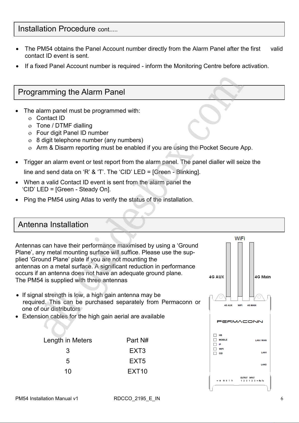
Screw the antennas onto the 4G Main & Aux SMA connectors; note a single antenna con-
nected to 4G Main is sufficient if the installation is not using the 4G Router feature.
Apply 10 - 15Vdc to the power terminals. Power is normally obtained from the Alarm Panel. If
you are using an independent power supply make sure that you have a common negative.
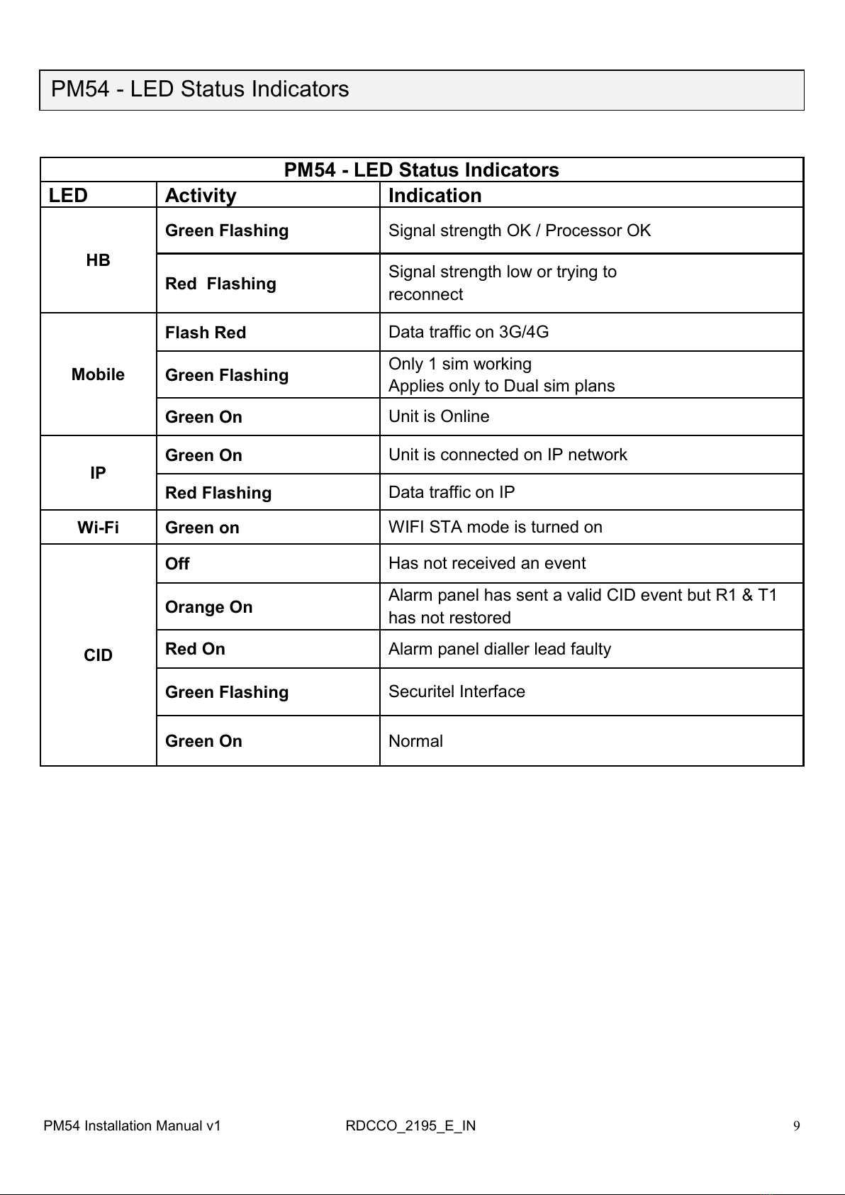
The ‗HB‘ LED indicates signal strength and if the processor is operating.
Operational + Good Signal = [Green –Blinking]
Operational + Low Signal = [Red Blinking]
The PM54 may take up to 3 minutes to come ‗online‘
Connection to the cellular network is indicated by the
‗MOBILE‘ LED = [Green – Steady On]
If the signal strength is low you need to reposition the antenna and/or the unit or make use of a
high gain antenna.
To verify signal strength ‗Ping‘ the communicator using the Atlas portal. Signal strength must
be better than -94dBm for reliable communications.
If you are using the on-site internet, connect a CAT5/6 cable between the PM54 WAN port and
the local router or network point. The PM54 will automatically obtain an IP address if it is set to
DHCP (Reset).
Connection to the internet is indicated by the ‗IP‘ LED. [Green – Steady On]
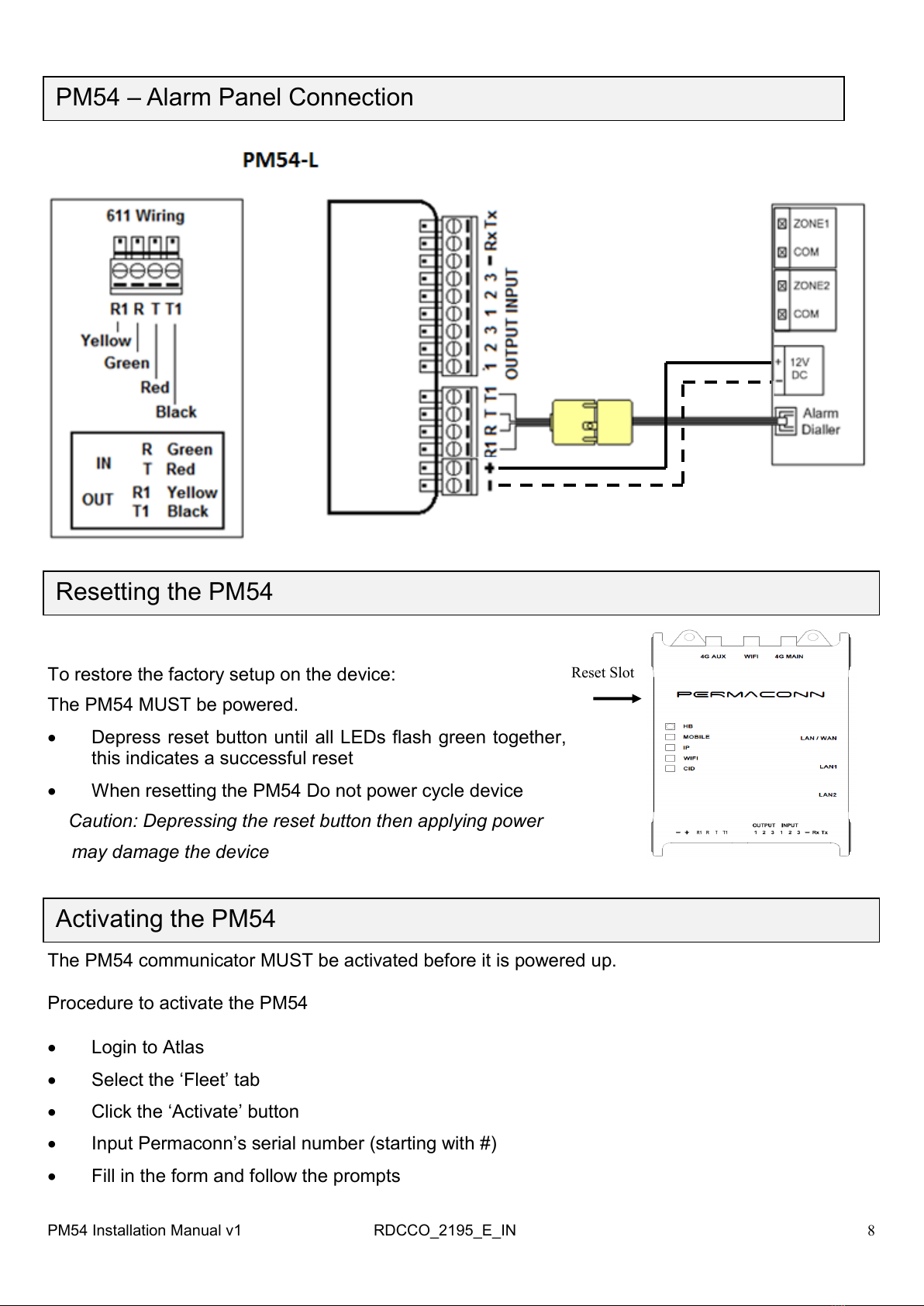
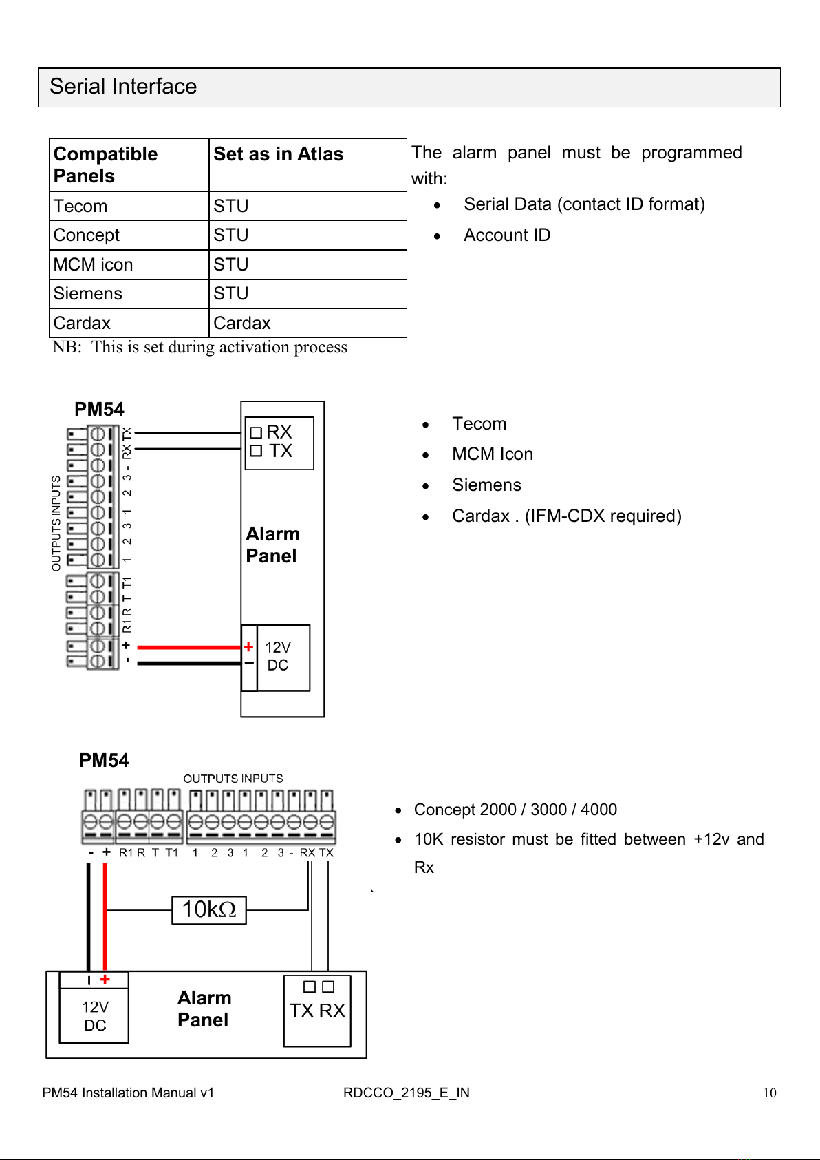
A four wire connection is required between the Alarm Panel dialler and the PM54.
Option 1: Plug the original alarm panel dialler lead into the 611 socket on the
PM54 to connect the alarm panel.
Option 2: Use a 4 core cable between PM45 and alarm panel dialler terminals. Connection
diagrams available: https://www.permaconn.com/installer-zone/technical-addendums
‗Ring‘ & ‗Tip‘ as the input and ‗R1‘ & ‗T1‘ as the return line. If the return line is not connected
the ‗CID‘ LED will be [Red - On] indicating a fault. This lead is also used to monitor the inter-
connectivity between the Alarm Panel dialler and the PM54. If the dialler lead is removed a
‗Dialler Lead Interface Fail‘ event will be sent to the Monitoring Centre. This will indicate that
the panel has lost connectivity with the PM54
.
Installation Procedure PM54
PM54 Installation Manual v1 RDCCO_2195_E_IN
All manuals and user guides at all-guidesbox.com

6
The PM54 obtains the Panel Account number directly from the Alarm Panel after the first valid
contact ID event is sent.
If a fixed Panel Account number is required - inform the Monitoring Centre before activation.
Installation Procedure cont.....
The alarm panel must be programmed with:
Contact ID
Tone / DTMF dialling
Four digit Panel ID number
8 digit telephone number (any numbers)
Arm & Disarm reporting must be enabled if you are using the Pocket Secure App.
Trigger an alarm event or test report from the alarm panel. The panel dialler will seize the
line and send data on ‗R‘ & ‗T‘. The ‗CID‘ LED = [Green - Blinking].
When a valid Contact ID event is sent from the alarm panel the
‗CID‘ LED = [Green - Steady On].
Ping the PM54 using Atlas to verify the status of the installation.
Programming the Alarm Panel
Antenna Installation
Antennas can have their performance maximised by using a ‗Ground
Plane‘, any metal mounting surface will suffice. Please use the sup-
plied ‗Ground Plane‘ plate if you are not mounting the
antennas on a metal surface. A significant reduction in performance
occurs if an antenna does not have an adequate ground plane.
The PM54 is supplied with three antennas
If signal strength is low, a high gain antenna may be
required. This can be purchased separately from Permaconn or
one of our distributors
Extension cables for the high gain aerial are available
Length in Meters Part N#
3 EXT3
5 EXT5
10 EXT10
RDCCO_2195_E_INPM54 Installation Manual v1
All manuals and user guides at all-guidesbox.com
all-guidesbox.com

7
Outputs
There are three (3) outputs available.
Outputs are ‗Open Collector‘ @50mA switching 12vDC negative—for heavier loads a re-
lay must be used.
Ensure there is a common negative between the PM54 and the device being switched.
The outputs can be opened, closed or pulsed using the Atlas web portal
The outputs can only be pulsed when using the Pocket Secure App.
Refer to the technical addendums for detailed key switch information.
www.permaconn.com / Installer Zone / Technical Addendums
Device Outputs
Compatible with ‗Pocket Secure‘ remote control App. Available on the Apple,
Google Play and Windows store
Device Inputs
There are three (3) inputs on the PM54
Inputs are programmed as 24hour Instant Zone types.
Inputs are sealed with a 3.3kresistor if used.
NB: Do not seal inputs if not used.
Input CID Part Zone
AUX 1 140 0 981
AUX 2 140 0 982
AUX 3 140 0 983
PM54 Installation Manual v1 RDCCO_2195_E_IN
EOL resistor colour code for Inputs on the PM54
All manuals and user guides at all-guidesbox.com

8
PM54 Installation Manual v1 RDCCO_2195_E_IN
PM54 –Alarm Panel Connection
Resetting the PM54
To restore the factory setup on the device:
The PM54 MUST be powered.
Depress reset button until all LEDs flash green together,
this indicates a successful reset
When resetting the PM54 Do not power cycle device
Caution: Depressing the reset button then applying power
t may damage the device
Reset Slot
Activating the PM54
The PM54 communicator MUST be activated before it is powered up.
Procedure to activate the PM54
Login to Atlas
Select the ‗Fleet‘ tab
Click the ‗Activate‘ button
Input Permaconn‘s serial number (starting with #)
Fill in the form and follow the prompts
All manuals and user guides at all-guidesbox.com

9
PM54 - LED Status Indicators
LED Activity Indication
HB
Green Flashing Signal strength OK / Processor OK
Red Flashing Signal strength low or trying to
reconnect
Mobile
Flash Red Data traffic on 3G/4G
Green Flashing Only 1 sim working
Applies only to Dual sim plans
Green On Unit is Online
IP
Green On Unit is connected on IP network
Red Flashing Data traffic on IP
Wi-Fi Green on WIFI STA mode is turned on
CID
Off Has not received an event
Orange On Alarm panel has sent a valid CID event but R1 & T1
has not restored
Red On Alarm panel dialler lead faulty
Green Flashing Securitel Interface
Green On Normal
PM54 Installation Manual v1 RDCCO_2195_E_IN
All manuals and user guides at all-guidesbox.com

10
Serial Interface
The alarm panel must be programmed
with:
Serial Data (contact ID format)
Account ID
Tecom
MCM Icon
Siemens
Cardax . (IFM-CDX required)
PM54
Alarm
Panel
PM54 Installation Manual v1 RDCCO_2195_E_IN
Concept 2000 / 3000 / 4000
10K resistor must be fitted between +12v and
Rx
Compatible
Panels
Set as in Atlas
Tecom STU
Concept STU
MCM icon STU
Siemens STU
Cardax Cardax
NB: This is set during activation process
PM54
Alarm
Panel
All manuals and user guides at all-guidesbox.com

11
Upload / Download (Using Permaconn 4G or IP)
Panel Client Software (PCS) is a virtual modem application that enables remote access to the
alarm panels using wireless 4G or Ethernet connec-
tion.
If using Serial Data as a monitoring path:
Connect the panel’s dialler to the PM54 to allow for
upload / download (PCS) capability, an example of
this is the Tecom & Concept panels
Note: Disable fax machine defeat and call back.
Enable one (1) call to answer, three (3) rings
Panel Software
Tecom V8 & V10 Titan v3.02+ / Forcefield v6.4+ / Titan CT
NX4 / 16 / 128 Reliance DL900 v4.01+ / DLX900
DL150 / 250 / 300 DASLOAD v6.0
Solution 844 / 16 / 880 A-Link Plus v4.12+
Solution 16i / 16 Plus / 64 Solution Link v1.2.3+
Solution 6000 Solution Link v2.1.1+
Solution 2000 & 3000 A-Link Plus v5.00+
DSC PC4020 / PC1616 DLS2002
DSC PC1616 + PC1864 DLS-5 (v4.2)
Crow Runner 8 / 16 ULD16 (v2.0.0.1+)
Paradox MG-5050 & EVO-192 Winload (v5.50+)
Ness D8 NessComms (v5.6.0.0+)
Risco LightSYS Config Software (v2.1+)
MCM Icon8 MCM Connect v5.45
Concept 3000 & 4000 Insight Installer (v5.4.10) & Wdirect 6.0+
Digiflex Vision 16 / 64 Vision Link
Protege' LE Protege' SE
Texecom Wintex
PM54 Installation Manual v1 RDCCO_2195_E_IN
Monitoring
Up/Dn
PCS
List of compatible panels and software
PM54
Alarm
Panel
All manuals and user guides at all-guidesbox.com
all-guidesbox.com

12
IP Setup
PM54 Installation Manual v1 RDCCO_2195_E_IN
Before you start you need the following:
Access to the Atlas portal
Connect the PM54 to the on-site internet gateway with a standard CAT5/6 patch lead.
The PM54 must be online (via IP or 4G) and accessible in Atlas to make changes.
To utilize an on-site internet connection:
Navigate to the IP then WAN tab
Tick ―Enable WAN Connection‖ and apply
To configure the device for DHCP:
Select ‗DHCP‘ for the ‗Connection Type‘ and apply
To configure the device with a static IP:
Select ‗Static‘ for the ‗Connection Type‘ and apply
Enter the desired IP, mask and Reset gateway
If using the customers‘ router ensure the
following ports are not blocked:
Overview
Overview
Internet
WAN
LAN
WiFi AP
4G Port
Forward
Applications
PM54
Internet IP Address
Internet
Physical Type
Status
IP Address
LAN
IP Address
Subnet Mask
Wi-Fi AP
Active Client
LAN1 LAN2 AP
This is View only
Port Protocol
11443 TCP
55300 UDP
55530 UDP
59681 UDP
All manuals and user guides at all-guidesbox.com

13
Configure the WAN interface to connect to an on-site Internet Gateway
This is View only
WAN disabled (Reset)
Utilising the customers‘ internet:
1: Connect a Cat5 / 6 cable between the WAN port on the PM54 to the customers‘ internet router
2: Tick the Enable WAN connection press save. This will cause the PM54 to reset.
The PM54 utilizes the DHCP protocol to obtain an IP address (Reset Config).
IP LED solid green indicates internet access
IP LED flashing green indicates connection to the customers‘‘ router but no internet connection
Internet
Router
PM54
PM54
Router Internet
X
Port 55530 UDP may be blocked
IP Setup cont.....
PM54 Installation Manual v1 RDCCO_2195_E_IN
All manuals and user guides at all-guidesbox.com

14
Additional WAN settings
Option 1: Ethernet Cable - Connect a
RJ45 Patch lead between the WAN on the
PM54 and a port on the customers router.
WiFi STA
Configure the WAN interface to connect to an on-site Internet Gateway
Option 2: WiFi STA - This will allow WiFi
connection from the PM54 to the customers
router.
PM54 Installation Manual v1 RDCCO_2195_E_IN
IP Setup cont.....
Name of customers Wi-Fi network
Security Mode options
Choosing other than none, will prompt for
the network key/password
WPA-PSK
WPA2-PSK
WPA-PSK + WPA2-PSK
DHCP: Allows the PM54 to automatically
obtain an IP address
Static: Allows a fixed IP address in the PM54
All manuals and user guides at all-guidesbox.com

15
Configure the LAN interface to set a Reset gateway for connected devices and optionally enable
the DHCP server to assign IP‘s to connected devices
Configure a Wi-Fi Hotspot to connect wireless clients and sensors
IP Setup cont.....
PM54 Installation Manual v1 RDCCO_2195_E_IN
Wi-Fi Enabled
Disabled (Reset)
Tick box to enable
Network name as seen by Wi-Fi client devices
DHCP Range setting
Example shown: Limit 100—150
Is IP 192.168.111.100—192.168.111.150.
Lease Time is how long the IP address is reserved for
security setting: WPA-PSK
WPA2-PSK
WPA-PSK + WPA2-PSK
All manuals and user guides at all-guidesbox.com

16
IP Setup cont.....
RDCCO_2195_E_INPM54 Installation Manual v1
To use the Port forward option, please call Permaconn to obtain a Data Plan containing a
Public IP address, there are a limited number available.
Allow inbound connections to devices that are connected to the PM54 LAN port from the internet
Using the standard Data Plan the IP Address
field is hidden.
Enabled
Enabled
123.123.123.123
Port Forwarding must be done in Atlas, Once the IP Address can be viewed select the ‗add‘ button
Port Forward setup will appear
TCP
UDP
TCP + UDP
Select Add when completed
All manuals and user guides at all-guidesbox.com
all-guidesbox.com

17
WWW
DVR or NVR
E.g IP 111.111.111.111
Port 8080
E.g IP 192.168.0.222
Port 80
LAN
DVR
TCP
8080
192.168.0.222
80
IP Setup cont.....
Port Forwarding example: Using the PM54 as an Internet Router
PM54 Installation Manual v1 RDCCO_2195_E_IN
All manuals and user guides at all-guidesbox.com

18
Device Use Case
Standalone Alarm Communicator providing an Internet Gateway
This configuration will deliver alarm events to the control room, allow remote UDL of the alarm
panel, allow remote management of the Input / Output via Pocket Secure and provide an internet
connection to both wireless and Wi-Fi devices connected to the PM54 device.
PM54 Installation Manual v1 RDCCO_2195_E_IN
All manuals and user guides at all-guidesbox.com

19
Device Use Case cont.....
Alarm Communicator providing a fallback Internet Gateway
This configuration will deliver alarm events to the control room, allow remote UDL of the alarm
panel, allow remote management of the Input / Output via Pocket Secure and provide an internet
connection to devices connected to the PM54 device; (if the internet connection provided by the on
-site Wi-Fi router fails). This configuration provides a redundant internet connection. The PM54 can
connect to the Wi-Fi router via a cable if convenient otherwise it may connect as a Wi-Fi client to
avoid cabling effort.
PM54 Installation Manual v1 RDCCO_2195_E_IN
All manuals and user guides at all-guidesbox.com

20
Transmission Delay Times
Messages originating from the Alarm Panel are forwarded immediately.
Alarm Panel ‗Dialler Interface Lead Fail‘ is sent if not restored within 90 seconds.
Arm / Disarm reporting will occur after the alarm panel‘s programmed exit/entry delay.
Event
ID
Part Point
ID
Description
313 00 954 Engineering Reset —No Action Required
350 00 953 Fail to Communicate —Communicator experienced trouble sending
signals, Do not expect restore.
352 00 956 Dialler Interface Lead Fail —Issue with dialler lead between
Permaconn communicator and Alarm Panel.
356 00 968 Permaconn Communicator —IP path poll fail.
356 00 969 Permaconn Communicator —Cellular network path poll fail.
356 00 970 Permaconn Communicator —Communicator is offline.
140 00 981 Auxiliary 1 —Auxiliary input alarm on communicator.
140 00 982 Auxiliary 2 —Auxiliary input alarm on communicator.
140 00 983 Auxiliary 3 —Auxiliary input alarm on communicator.
300 00 984 Panel ID Clash—When two (2) Permaconn devices are reporting to
the same Control Room on the same line number using the same
account number.
NB: Check in Atlas for duplicate account number.
Permaconn Contact ID Event Template
PM54 Installation Manual v1 RDCCO_2195_E_IN
All manuals and user guides at all-guidesbox.com
This manual suits for next models
1
Table of contents
Other Permaconn Cell Phone manuals