4 Permasense Ltd, Alexandra House, Newton Road, Manor Royal, Crawley, RH10 9TT, UK
www.permasense.com permasense.support@emerson.com +44 20 3002 0922
Optional tooling –if preferred, an electric screwdriver may be used instead of the supplied tools to speed
up the installation process. This is not included in IK220 installation kit.
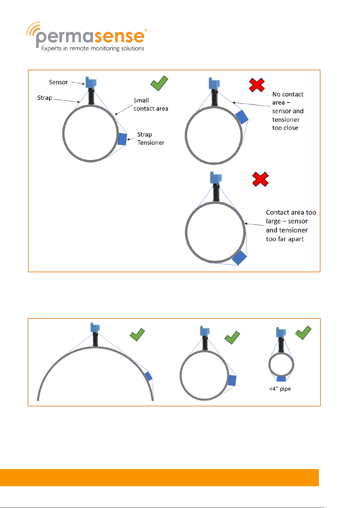
Alternative shoe –if the sensor is to be installed on a pipe with a diameter less than 4”, an alternative shoe
should be ordered which is designed to fit to small diameter pipes. Please consult Permasense.
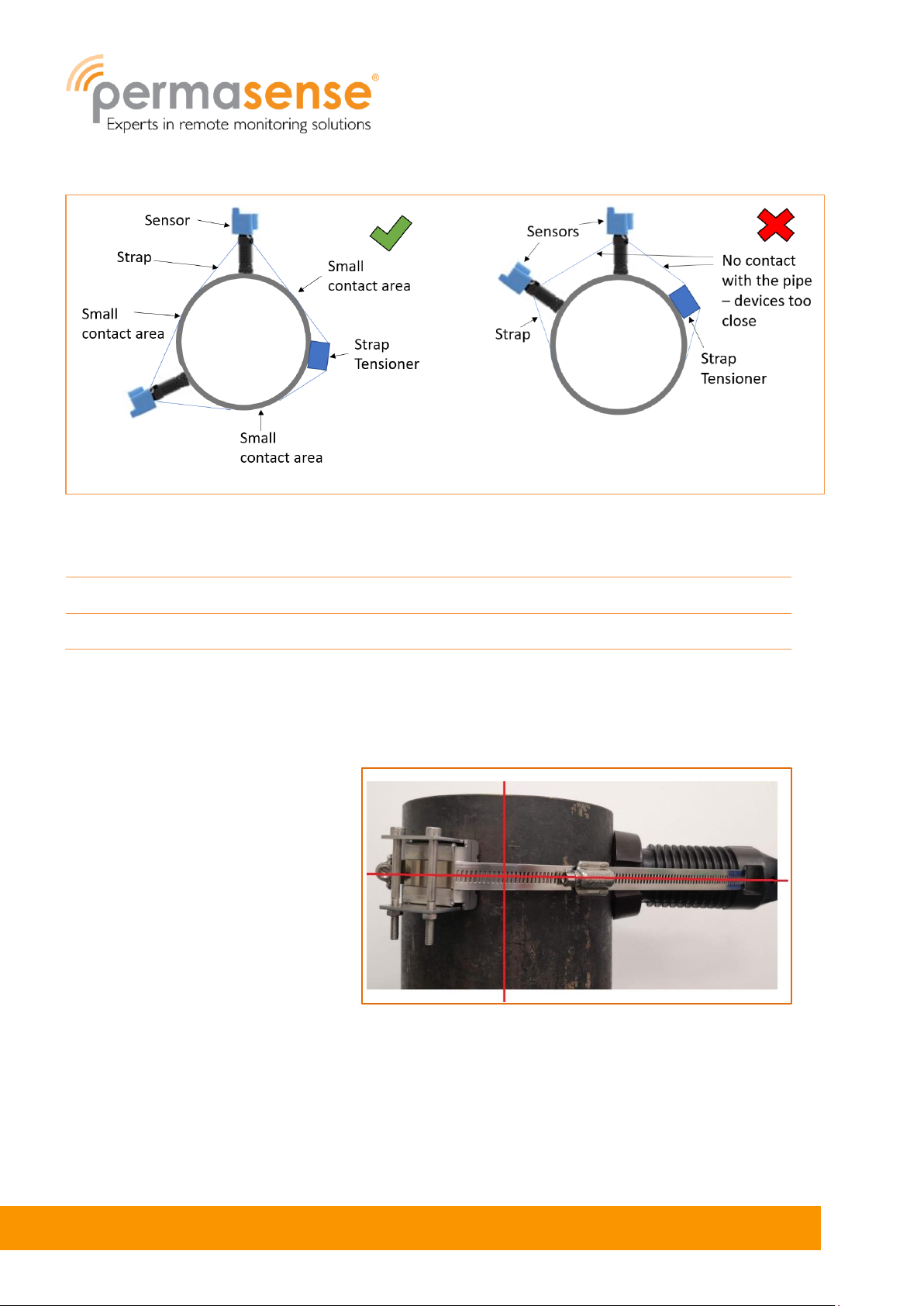
Task 1. Mounting the sensor
Note: Two people are required for this operation.
PPE of gloves and safety glasses or full face visor are recommended.
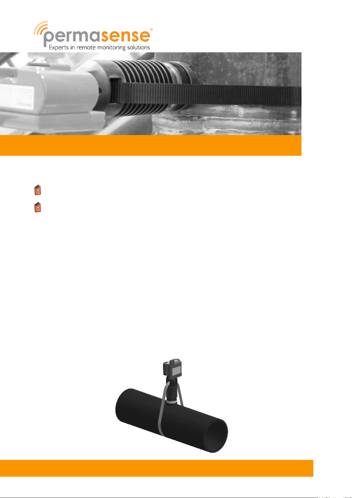
1. Identify the location where the sensor is to be fixed. The securing strap can be installed around pipes
up to 1m (40 inches) in diameter. Ensure all cladding and insulation is removed around the
circumference of the pipe at the desired sensor location.
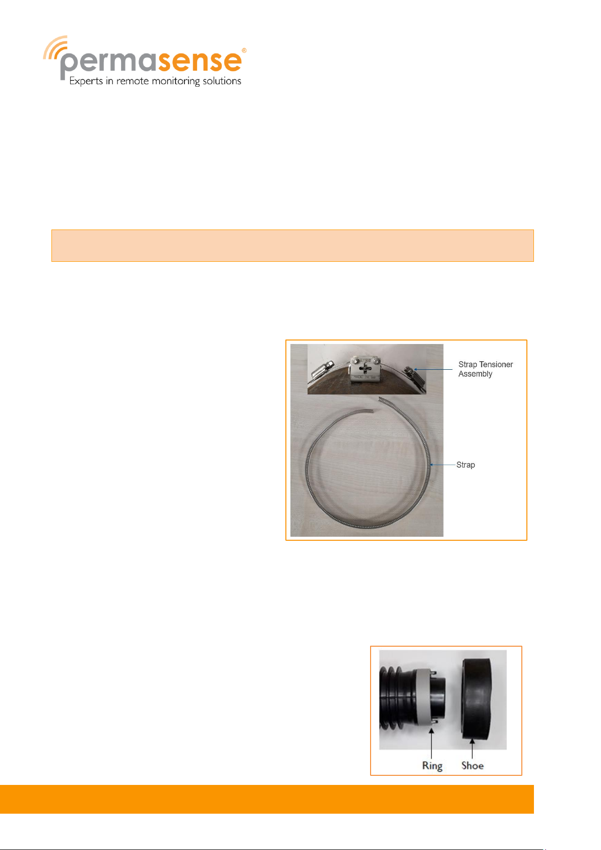
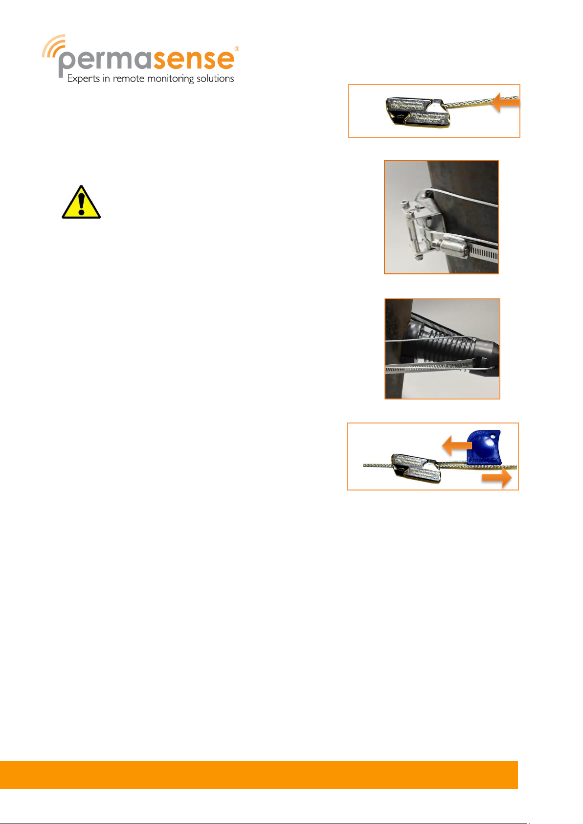
2. Unbox the strap tensioner and strap from the packaging.
3. Cut a length of strap by wrapping it around the
pipe and adding 25cm [10”]. As a rough guide, if
the diameter is D cm / inches, the length can be
approximated by (3 x D + 25) cm or (3 x D +
10) inches. Feed the strap into one end of the
strap tensioner and using the flathead
screwdriver or wrench and socket provided,
turn the screw on the tensioner until the end
of the strap emerges from under the worm
drive (at least 5 turns of the worm-screw is
required).
4. Clean the area where the sensor will touch the pipe, mainly to remove any particles which might keep
the transducer away from the pipe surface or damage the face of the transducer. A permanent marker
may be used to show exactly where each sensor is to be placed on the pipe.
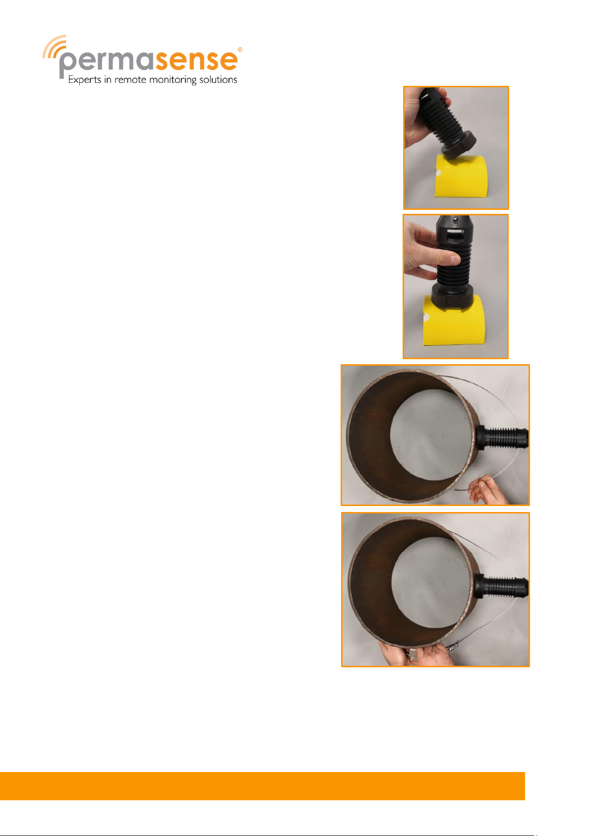
5. Remove the protective cap from the sensor.
Note: Ensure tools and fastenings are kept away from the sensor when the cap is removed as there is
a strong magnetic field at the end of the sensor.
If the rubber shoe needs to be refitted, ensure the ring is still in
place, then fit the shoe onto the sensor by pushing the two pegs
protruding from the foot of the sensor into the holes in the shoe.
If the ring is missing, do not use the sensor.
If the sensor is to be placed on a pipe less than 4” in diameter, fit
the alternative shoe.