PESA Cheetah V5 User manual

CHEETAH V5 MODULES
1
CHEETAH V5 DVI/RGBHV Extenders
July 26, 2005
Manual: 81-9059-0571-0 Revision B

CHEETAH V5 MODULES 81-9059-0571-0 REV.B
2
Copyrights and Trademarks
©2004. All rights reserved. This information may not be reproduced in any manner without the prior written consent of the manufacturer.
Information in this document is subject to change without notice and the manufacturer shall not be liable for any direct, indirect, special, incidental or
consequential damages in connection with the use of this material.
All trademark and trade names mentioned in this document are acknowledged to be the property of their respective owners.
Disclaimer
While every precaution has been taken in the preparation of this manual, the manufacturer assumes no responsibility for errors or omissions. Neither does
the manufacturer assume any liability for damages resulting from the use of the information contained herein. The manufacturer reserves the right to
change the specifications, functions, or circuitry of the product without notice.
The manufacturer cannot accept liability for damage due to misuse of the product or due to any other circumstances outside the manufacturer’s control
(whether environmental or installation related). The manufacturer shall not be responsible for any loss, damage, or injury arising directly, indirectly, or
consequently from the use of this product.
Cautions and Notes
The following symbols are used in this guide:
CAUTION. This indicates an important operating instruction that should be followed to avoid any potential
damage to hardware or property, loss of data, or personal injury.
NOTE. This indicates important information to help you make the best use of this product.

DECLARATION OF CONFORMITY
3
EUROPEAN UNION DECLARATION OF CONFORMITY
This is to certify that, when installed and used according to the instructions in this manual, together with the specified cables and the maximum
cable length <3m, the Units are shielded against the generation of radio interferences in accordance with the application of Council Directive
89/336/EEC as well as these standards:
EN 55022: Fiber+STP 1999 Class B
EN 55022: UTP 1999 Class A
EN 55024: 1999
IEC 61000-4-2: 2001
IEC 61000-4-3: 2001
IEC 61000-4-4: 2001
EN 61000-3-2 2001
EN 61000-3-3 2002
The device was tested in a typical configuration with PC.

CHEETAH V5 MODULES 81-9059-0571-0 REV.B
4
Safety Precautions and Installation Guidelines
To ensure reliable and safe long-term operation, please note the following installation guidelines:
• Only use in dry, indoor environments.
• If the building has 3-phase AC power, try to ensure that equipment connected to the Local and Remote units is on the same phase.
• Ensure that the system connected to the Local unit is connected to power ground.
• Ensure that the monitor connected to the Remote unit is connected to power ground and does not use an isolated power supply.
• The Remote unit, Local unit and any power supplies can get warm. Do not locate them in an enclosed space without any airflow.
• Do not place a power supply directly on top of a unit.
• Do not obstruct a unit’s ventilation holes.
To safeguard against personal injury and avoid possible damage to equipment or property, please
observe the following:
• Only use power supplies originally supplied with the product or manufacturer-approved
replacements. Do not attempt to dismantle or repair any power supply. Do not use a power supply if
it appears to be defective or has a damaged case.
• Connect all power supplies to grounded outlets. In each case, ensure that the ground connection is
maintained from the outlet socket through to the power supply’s AC power input.
• Do not attempt to modify or repair this product, or make a connection from the Fiber link interface
(LC) to any other products, especially telecommunications or network equipment.

SAFETY PRECAUTIONS AND INSTALLATION GUIDELINES
5
Optical Models
These are Class 1 Laser products. Singlemode transceivers comply with IEC 60825-1 and FDA 21 CFR 1040.10 and 1040.11. To meet laser safety
requirements, the transceivers shall be operated within the absolute maximum ratings.
The use of optical instruments with this product may cause an eye hazard. All adjustments have been
made at the factory prior to shipment of the device. No maintenance or alteration to the device is
required.
Tampering with or modifying the performance of the device will result in voided product warranty.
Usage Restrictions
Optical ports must be terminated with an optical connector or with a dust plug. Failure to adhere to the above restrictions could result in a modification
that is considered an act of “manufacturing” and will require, under law, recertification of the modified product with the U.S. Food and Drug
Administration (ref. 21 CFR 1040.10(i)).

CHEETAH V5 MODULES 81-9059-0571-0 REV.B
6
Contents
1. Quick Setup 7
1.1 Video Input/Output 8
1.2 Command Summary 9
2. Overview 9
2.1 Introduction 9
2.2 Glossary 10
2.3 Features 13
2.4 Product Range 14
2.5 Compatibility 15
2.6 How to Use This Guide 16
3. Installation 16
3.1 Package Contents 16
3.2 Interconnection Cable Requirements 17
3.3 System Setup 18
3.4 Diagnostic LEDs 20
4. Device Control 20
4.1 Opening the OSD 22
4.2 Using the OSD 24
5. Monitor Setup 32
6. Extender Setup 33
6.1 Overview 33
6.2 Setup Instructions for VGA Input 34
7. Troubleshooting 35
7.1 Video 35
Appendix A: Rack Mount Options 38
Appendix B: System Upgrade 40
Appendix C: Video Modes and Frame Rates 41
Appendix D: Audio Option 43
Appendix E: Calling Technical Support 45
Appendix F: Specifications 46
Appendix G: Connectors and Cables 48

7
QUICK SETUP
This section briefly describes how to install your Cheetah V5 system and optimize the video signals. Unless you are an experienced user, we recommend
that you follow the full procedures described in the rest of this manual. Refer to the command summary on page 9 when following this procedure.
Install system
1. Connect Remote unit (RX) to source.
2. Connect Local unit (TX) to CPU or switch.
3. Connect Local and Remote units with matching interconnection cable
(Singlemode fiber).
4. Power up the system.
Carry out the Monitor Setup
procedure (please refer to its
manual and see page 40 in
this manual).
Carry out
V
GA Input Setup procedure
(please follow the instructions on page 42).
Done
Yes
No
Do you have a
DVI monitor?
Do you have a
DVI source?
Do you
have a flat screen
(TFT)?
No
No
Yes
Yes

CHEETAH V5 MODULES 81-9059-0571-0 REV.B
8
VIDEO INPUT/OUTPUT
If possible, always use DVI output from your computer’s video card and DVI input to a monitor. This provides the optimum video signal. If you use a
VGA output from your graphic source, the DVI Local unit must digitize the signal prior to transmission. Similarly, if your remote TFT screen uses a
VGA input, it must digitize the signal from the Remote unit. In both cases, the built-in video processors must determine the resolution and pixel phase for
an optimized digitization. Your DVI Extender allows you to optimize the video signal manually or automatically using its on-screen utility (see Chapter
4). If you are using a VGA input to a TFT monitor, please follow the manufacturer’s instructions.
You may have several possible options for video source output/monitor input. If this is the case, for the optimum video quality, please select the highest
ranked available combination from the following table:
Video Quality Local Unit input Remote Unit output
1 DVI DVI
2 DVI VGA
3 VGA DVI
4 VGA VGA

9
COMMAND SUMMARY
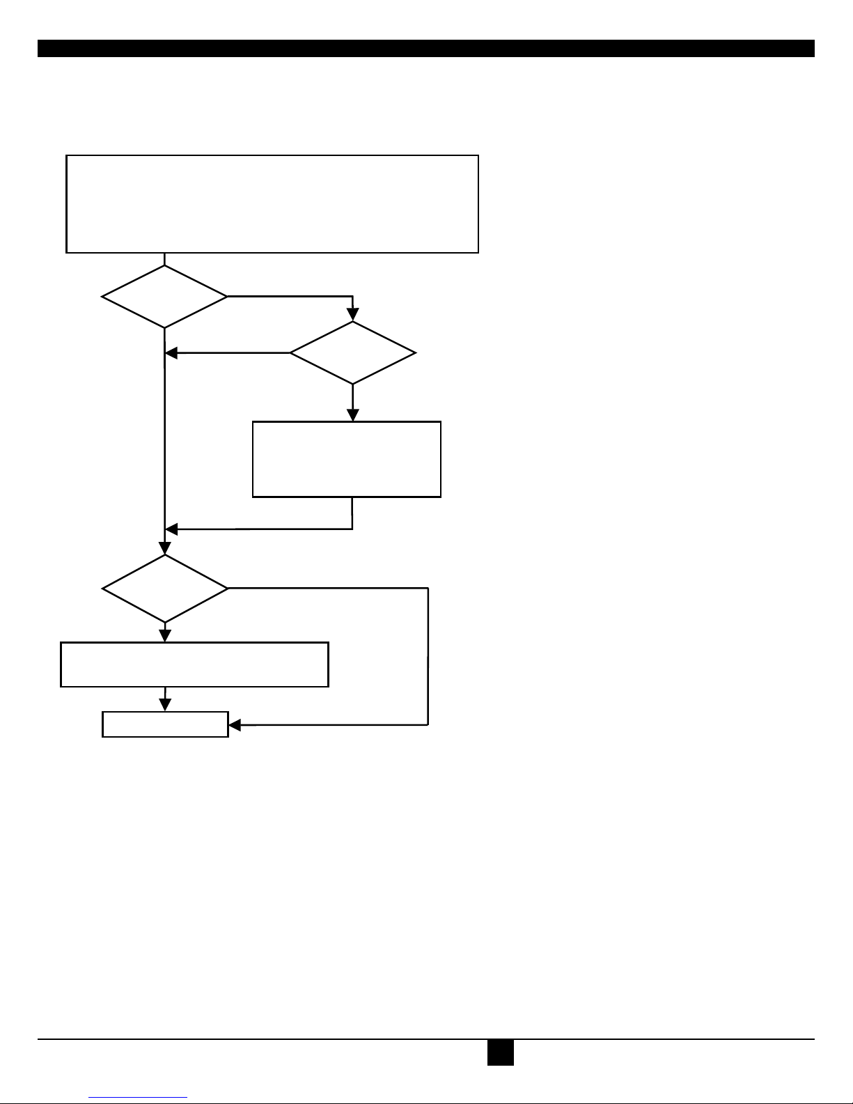
The following table summarizes the ‘hot’ key command sequences used in system configuration and video tuning on a Remote unit console.
Command Keyboard
at Remote unit
Terminal or
Windows Utility program*
Enter OSD <Left Control>
+ <Left Shift> + <I>
<O> + <S> + <D>
+ <Enter>
Exit OSD <ESC> <X>
Select next position <Right Arrow> <R>
Select previous
position <Left Arrow> <L>
Select Submenu <Enter> <S>
Select parameter
modification <Enter> <S>
Increase parameter <Right Arrow> <R>
Decrease parameter <Left Arrow> <L>
Accept and store
modified parameter <Enter> <S>
Back to the Menu
selection
* Commands are not case-sensitive.
OVERVIEW
INTRODUCTION
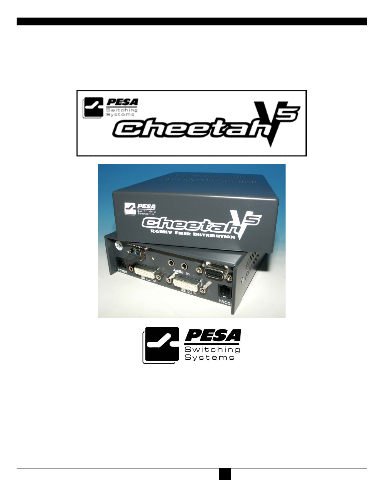
A basic Cheetah V5 system comprises a Local unit (transmitter) and a Remote unit (receiver). The Local unit connects directly to the computer using the
supplied cable(s). The user console (monitor) attaches to the Remote unit. The Remote and Local units communicate video information along the
interconnecting cable (see Figure 1). Local units offer dual access, allowing the connection of a second user console close to the computer. With the
optional V5A2 models, you can also use the Cheetah V5 units to communicate stereo audio.
Cheetah V5 modules enable high-resolution video and optional stereo audio to be communicated up to:
• 1200ft (400m) over Multimode fiber cable (50/125µ).
• 600ft (200m) over Multimode fiber cable (62.5/125µ).
• 6¼ miles (10km) over Singlemode fiber cable (9/125µ).
In a digital application (DVI input and output), there is no loss of picture quality irrespective of extension distance and no adjustments are required. The
Cheetah V5 modules also support traditional analog VGA as well as digital DVI. All combinations of DVI and VGA (graphics cards and monitors) are
supported, allowing equipment to be mixed. In a mixed analog/digital application, some adjustment of the video signal is necessary to optimize the
analog-digital signal conversions. Cheetah V5 modules are equipped with various automatic and manual video correction tools in an on screen utility (see
page 20).

CHEETAH V5 MODULES 81-9059-0571-0 REV.B
10
GLOSSARY
The following terms are used in this guide:
Multimode Any multimode fiber cable 50/125µ or 62.5/125µ
Singlemode Any singlemode fiber cable 9/125µ
PSU The desktop power supply connected to the Local/Remote unit.
Dual Access A system allowing connection of Local and Remote user consoles.
Single Head An extender system that supports one monitor.
Coax Recommended coax is Belden 8281 or equal

11
Figure 1 Cheetah V5 System
Local Access
V
ideo Support
Audio extension
options
LOCAL unit
REMOTE unit

CHEETAH V5 MODULES 81-9059-0571-0 REV.B
12

13
FEATURES
The Cheetah V5 Modules offer the following features:
• Support for high video resolution over extended distances:
1600x1200@60Hz over all allowed distances
all lower resolutions with refresh rates of at least 75Hz
• All models come with dual access, to allow local or remote operation
(Local DVI access limited to screen resolutions up to 1280x1024).
• All control and video tuning carried out using an on screen display (OSD) with settings stored in EEPROM memory.
• Local/Remote unit firmware and settings flash upgradeable.
• Stereo audio (16-bit digitized) support on certain models enables high-quality, low-noise audio extension.
• Status indicator LEDs on each device.
• Small footprint chassis.
• Rack mount options available.
• CPU cables + Adapters included.

CHEETAH V5 MODULES 81-9059-0571-0 REV.B
14
PRODUCT RANGE
There are two products in the ranges:
Primary Modules- Video Only
CH1612TX-V5 DVI/VGA Extender, Singlemode Transmitter
CH1612RX-V5 DVI/VGA Extender, Singlemode, Receiver
CH1612TX-V5C DVI/VGA Extender, Coax, Transmitter
CH1612RX-V5C DVI/VGA Extender, Coax, Receiver
CH1612TX-V5R DVI/VGA Extender, Singlemode, Transmitter, Rackmount
CH1612RX-V5R DVI/VGA Extender, Singlemode, Receiver, Rackmount
CH1612TX-V5CR DVI/VGA Extender, Coax, Transmitter, Rackmount
CH1612RX-V5CR DVI/VGA Extender, Coax, Receiver, Rackmount
Primary Modules-Video and Audio
CH1612TX-V5A2 DVI/VGA Stereo Audio, Singlemode Transmitter
CH1612RX-V5A2 DVI/VGA Stereo Audio, Singlemode Receiver
CH1612TX-V5A2C DVI/VGA Stereo Audio Extender, Coax, Transmitter
CH1612RX-V5A2C DVI/VGA Stereo Audio Extender, Coax, Receiver
CH1612TX-V5A2R DVI/VGA Stereo Audio Extender, Singlemode, Transmitter, Rackmount
CH1612RX-V5A2R DVI/VGA Stereo Audio Extender, Singlemode, Receiver, Rackmount
CH1612TX-V5A2CR DVI/VGA Stereo Audio Extender, Coax, Transmitter, Rackmount
CH1612RX-V5A2CR DVI/VGA Stereo Audio Extender, Coax, Receiver, Rackmount
Upgrade Kits
CHV5RMKIT Rack mount kit for above modules, 1RU, supports up to three modules
CHV5-DVICABLE Cable DVI
CHV5RMKIT3RU 3RU Frame, allows for up to 9 modules of any “-R” model. Internal power supply
and cooling fan.

15
COMPATIBILITY
Interface Compatibility
• (OPTION) Audio: Input and output are line-level. Amplified speakers are required.
• Analog Video: VGA to UXGA. Supports RGB, RGsB, RGBHV. Maximum resolution and refresh rates depend on cable length and cable type
• Digital Video: DVI single link for resolution up to 1600x1200 at 60Hz. Frame rates and colors depend on device type

CHEETAH V5 MODULES 81-9059-0571-0 REV.B
16
HOW TO USE THIS GUIDE
This guide describes the installation and configuration of the Cheetah V5 modules. Although the connection and operation of the system is relatively
straightforward, you should consider the following before getting started:
Connection & Compatibility
If you have purchased an Extender Kit, this will contain all the cables required to connect the Local unit to your PC. The Remote monitor and any audio
connects directly to the Remote unit.
For information about connection and installation, see Installation, page 16.
Interconnection Cable
For Cheetah V5 connections, use singlemode or multimode fibers (see Interconnection Cable Requirements, page 17.
Adjusting Video
Due to the digital nature of the transmitted signals, there is no distortion of video signals or skew problem.
If you do not have a DVI source and a DVI monitor, you will need to adjust the monitor and/or the Extender to the picture width and the pixel phase. You
can do this using the Auto Adjust or Manual Adjust procedures.
• For experienced users there is a Quick Setup section at the start of this guide
(see page 7).
• For the full procedure, see Monitor Setup and/or Extender Setup.
INSTALLATION
For first-time users, we recommend that you carry out a test placement, confined to a single room, before commencing full installation. This will allow
you to identify and solve any cabling problems, and experiment with the Cheetah V5 system more conveniently.
PACKAGE CONTENTS
You should receive the following items in your extender package (all types):
• Extender Remote unit.
• 6V DC 12W universal power supply for Remote unit.
• Extender Local unit.
• 6V DC 12W universal power supply for Local unit.
• 2x DVI-I to VGA adapter (DVI-I dual link male to HD15 female) connector.
• 1x VGA to DVI-I adapter (HD15 male to DVI-I dual link female) connector.
• Programming cable (DB9 female to RJ11 4p4c).
• User manual.
• 2x US-type power cord.
If anything is missing, please contact Technical Support (see Appendix E: Calling Technical Support).

17
INTERCONNECTION CABLE REQUIREMENTS
To connect the Local and Remote units you will need:
• Multimode Modules: single fiber cable 50µm or 62.5µm.
• Singlemode Modules: single fiber cable 9µm.
• Coax Modules: single coax cable, 8281 Belden or equal type coax.
•
• Power Supply
Connect the supplied 6V/DC power supplies to the Plug terminal on the rear of both Local and Remote units.

CHEETAH V5 MODULES 81-9059-0571-0 REV.B
18
SYSTEM SETUP
To install your Cheetah V5 system:
1. Switch off all devices.
2. Connect your monitor to the Remote unit
3. Connect the interconnect cable to the INTERCONNECT socket(s) as shown
4. Connect the 6V power supply to power the unit.
Only use the power supply originally supplied with this equipment or a manufacturer-approved
replacement.
5. Power up the system.

19
Figure 2 Cheetah V5 Remote Unit
Figure 3 Cheetah V5 Local Unit
DVI-I Connector – DVI and
VGA output – connect to
Remote console monitor
Connect 6V
Power supply
Programming connector –
for firmware upgrades
INTERCONNECT – carries video
and data signals – connect to
Local unit
INTERCONNECT – carries video
and data signals – connect to
Remote unit
Connect to Local
console monitor
Connect 6V
Power supply
Programming
connector – for
firmware upgrades
Connect to CPU
video card output
DVI-I Connectors (Digital or Analog)

CHEETAH V5 MODULES 81-9059-0571-0 REV.B
20
DIAGNOSTIC LEDS
Each Extender unit is fitted with four indicator LEDs: Communication Error, Link Status, Device Ready and Video Signal. The Indicator LEDs are
located in the same positions on all models. The Communication Error and Link Status LEDs are to the left and right, respectively, of the Interconnect
sockets. The Device Ready and Video Signal LEDs are next to the Power socket.
As an example, the location of the LEDs is shown below for Remote and Local units:
Communication Error Link Status Communication Error Link Status
Video Signal Device Ready Device Ready Video Signal
(Green) (Red) (Red) (Green)
Figure 4 Diagnostic LEDs on Remote (left) and Local (right) units
LED Appearance Diagnostics
Communication
Error
Off
Flashing
slow
medium
fast
No communication error for >60 minutes
Indicates number of communication errors during
previous 60 minutes:
1-2 (Fiber)
3-10 (Fiber)
10 (Fiber)
Error counter cleared automatically 60 minutes after previous communication error.
Link Status On
Flashing
Link connection is locked
Interconnection cable not connected or not
functioning
Device Ready
(Red LED)
Off
On
Device not ready
Device ready
Video Signal
(Green LED)
Off
On
No video signal or valid mode detected
Attached and valid mode detected
DEVICE CONTROL
If you are using the DVI output from your video card and the DVI input to a TFT monitor, no adjustment should be required. In other cases, when the
video signal is converted between analog and digital formats, either by the Local unit and/or the monitor, you may need to optimize the video signal using
the Extender’s on-screen display (OSD).
Version information
Screen resolution and
refresh rate
Main menu icons
Submenu/command icons
Menu title
Table of contents
Other PESA Extender manuals