PESA CHEETAH DRS series User manual

USER GUIDE
CHEETAH DRS SERIES AUDIO ROUTERS
MULTICHANNEL AUDIO DIGITAL INTERFACE
(MADI) ADAPTER
Publication: 81-9059-0597-0, Rev. B www.PESA.com
September 2015 Phone: 256.726.9200

CHEETAH DRS SERIES MADI ADAPTER
Publication 81-9059-0597-0, Rev. B
September 2015
I
We appreciate your confidence in our products. PESA produces quality, state-of-the-art A/V processing, routing
and distribution equipment designed to deliver our users the highest degree of performance, dependability and
versatility available anywhere. We want you to know that if you ever have a question or concern with a PESA
product, we have a team of engineers, technicians and customer service professionals available 24/7 every day
of the year to help resolve the issue.
Again thank you for choosing PESA, and we look forward to a long-term partnership with you and your facility.
S
ERVICE AND
O
RDERING
A
SSISTANCE
PESA
103 Quality Circle, Suite 210
Huntsville AL 35806 USA
www.PESA.com
M
AIN
O
FFICE
Tel: 256.726.9200
Fax: 256.726.9271
C
USTOMER
S
ERVICE
D
EPARTMENT
Tel: 256.726.9222 (24/7)
Toll Free: 800.323.7372
Fax: 256.726.9268
© 2015, 2006 PESA Switching Systems, Inc. All Rights Reserved.
Cheetah is a trademark of PESA Switching Systems, Inc. in the United States and/or other countries.
Microsoft, Windows, and Windows NT are either registered trademarks or trademarks of Microsoft Corporation in the United States and/or
other countries.
No part of this publication (including text, illustrations, tables, and charts) may be reproduced, stored in any retrieval system, or transmitted
in any form or by any means, including but not limited to electronic, mechanical, photocopying, recording or otherwise, without the prior
written permission of PESA Switching Systems, Inc.
All information, illustrations, and specifications contained in this publication are based on the latest product information available at the time
of publication approval. The right is reserved to make changes at any time without notice.
Printed in the United States of America.
As of publication, this product had not completed FCC compliance testing.
September 2015
December 2006

CHEETAH DRS SERIES MADI ADAPTER
Publication 81-9059-0597-0, Rev. B
September 2015
II
T
ABLE OF
C
ONTENTS
CHAPTER 1 ABOUT THIS MANUAL....................................................................................1-1
1.1 DOCUMENTATION AND SAFETY OVERVIEW ........................................................................ 1-1
1.2 WARNINGS,CAUTIONS,AND NOTES................................................................................... 1-1
1.2.1 Warning................................................................... Error! Bookmark not defined.
1.2.2 Caution.................................................................... Error! Bookmark not defined.
1.2.3 Note......................................................................... Error! Bookmark not defined.
CHAPTER 2 INTRODUCTION...............................................................................................2-1
2.1 DESCRIPTION .................................................................................................................... 2-1
2.2 FEATURES......................................................................................................................... 2-2
2.3 MADI MODULES .............................................................................................................. 2-2
2.3.1 Input Adapter........................................................................................................2-2
2.3.2 Output Adapter .....................................................................................................2-2
2.3.3 Adapter Module Connections ................................................................................2-3
2.3.4 DRS System Configuration Using MADI Adapters ...............................................2-4
CHAPTER 3 INSTALLATION.................................................................................................3-1
3.1 MADI MODULE INSTALLATION OPTIONS........................................................................... 3-1
3.2 MOUNTING AMADI MODULE IN ARACK-MOUNT CHASSIS............................................... 3-1
3.3 SYSTEM SYNCHRONIZATION .............................................................................................. 3-1
3.4 CONNECTION CHECKLIST................................................................................................... 3-1
CHAPTER 4 OPERATION.......................................................................................................4-1
4.1 AN INTRODUCTION TO THE PESA CHEETAH CONTROL SYSTEM.......................................... 4-1
4.2 PERC2000 GRAPHICAL USER INTERFACE .......................................................................... 4-2
4.3 HARDWARE AND ROUTER CONFIGURATION FILES .............................................................. 4-3
4.4 MADI INDICATOR LIGHTS................................................................................................. 4-3
4.5 MADI MODULE STATUS LIGHTS........................................................................................ 4-4
L
IST OF
F
IGURES
F
IGURE
2-1
C
HEETAH
DRS
MADI
A
DAPTER
–
T
YPICAL
M
ODULE AND
R
ACK
U
NIT
.......................................2-1
F
IGURE
2-2
C
ONNECTIONS TO
MADI
A
DAPTER
M
ODULE
(T
YPICAL
)..............................................................2-3
F
IGURE
2-3
128
X
128
N
ON
-R
EDUNDANT
R
OUTER
S
YSTEM WITH
MADI
I
NPUTS
...........................................2-5
F
IGURE
2-4
128
X
128
N
ON
-R
EDUNDANT
R
OUTER
S
YSTEM WITH
MADI
O
UTPUTS
........................................2-6
F
IGURE
2-5
128
X
128
N
ON
-R
EDUNDANT
R
OUTER
S
YSTEM WITH
MADI
I
NPUTS AND
O
UTPUTS
....................2-7
F
IGURE
2-6
128
X
128
R
OUTER
S
YSTEM WITH
R
EDUNDANT
P
OWER
&
C
ONTROLLER
.....................................2-9
F
IGURE
3-1
MADI
R
ACK
F
RAME
-
M
ODULE
I
NSTALLATION
...........................................................................3-1
F
IGURE
4-1
E
XAMPLE
PESA
C
HEETAH
C
ONTROL
S
YSTEM
.............................................................................4-1
F
IGURE
4-2
MADI
M
ODULE
F
RONT
P
ANEL
....................................................................................................4-4

CHEETAH DRS SERIES MADI ADAPTER
Publication 81-9059-0597-0, Rev. B
September 2015
1-1
Chapter 1 About This Manual
1.1 D
OCUMENTATION AND
S
AFETY
O
VERVIEW
This User Guide provides instructions for installation and operation of the MADI Adapter Module for
use with the Cheetah DRS Series Audio Routing Switchers built by PESA Switching Systems, Inc.
It is the responsibility of all personnel involved in the installation, operation, and maintenance of the
equipment to know all the applicable safety regulations for the areas they will be working in. Under no
circumstances should any person perform any procedure or sequence in this manual if the
procedural sequence will directly conflict with local Safe Practices. Local Safe Practices shall
remain as the sole determining factor for performing any procedure or sequence outlined in this
document.
1.2 C
AUTIONS AND
N
OTES
Cautions and Notes are addendum statements used in this guide that supply necessary information
pertaining to the text or topic they address. Caution statements typically notify you of steps or
procedures that could impede installation or operation; and/or cause damage to the equipment. Notes are
additional statements that typically provide added information that can simplify and/or enhance the use
or operating characteristics of the equipment. Examples of the graphic symbol used to identify each type
of statement and the nature of the statement content are shown below:
Caution statements identify conditions or practices that can result in
personal injury and/or damage to equipment if the instructions contained in
the statement are not complied with.
Notes are for information purposes only. However, they may contain
invaluable information important to the correct installation, operation,
and/or maintenance of the equipment.

CHEETAH DRS SERIES MADI ADAPTER
Publication 81-9059-0597-0, Rev. B
September 2015
Proprietary Information of PESA 2-1
Chapter 2 Introduction
2.1 D
ESCRIPTION
PESA’s MultiChannel Audio Digital Interface (MADI) Adapter for the DRS Series Audio Router
allows MADI compliant audio data streams to interface directly into a DRS router installation. This
manual assumes the user has access to PESA Publication 81-9059-0589-0, Cheetah DRS Series Audio
Routers, Technical Manual. It is also assumed that the user has a strong understanding of the system
components, hook-up and operational principles of a DRS system. If necessary, please take the time
now to read the DRS Technical Manual before proceeding with this discussion of the MADI Adapter.
The term MultiChannel Audio Digital Interface, or MADI, defines a digital data manipulation and
multiplexing technology conforming to standards as defined by AES10 1991 and revised in AES10
2003. MADI technology allows up to 64 AES compliant digital audio channels to be transmitted over a
single coaxial cable. Fiber optic module connectors are supplied for future product development and
implementation. PESA’s MADI adapter is available as an input device or an output device. The input
adapter receives the MADI compliant signal and processes the data into a data stream compliant with
the PESA proprietary Packet Audio Stream (PAS) bus protocol which can interface directly with the
DRS Data Exchange Engine. MADI audio sources are routed within the DRS system just as any
discrete signal would be. Likewise, the output adapter interfaces with the DRS DXE through the PAS
bus and generates a MADI compliant output data stream containing up to 64 audio signals. Figure 2-1
illustrates a typical MADI module and rack mount unit.
Figure 2-1 Cheetah DRS MADI Adapter – Typical

CHEETAH DRS SERIES MADI ADAPTER
Publication 81-9059-0597-0, Rev. B
September 2015
Proprietary Information of PESA 2-2
2.2 F
EATURES
Features of the DRS MADI Adapter include:
•Fully Compliant With AES10 1991 and AES10 2003 Specifications
•48kHz, 64 Time Slot MADI Bus (Default),
•Supports “Double Speed” 96kHz, 32 Time Slot MADI Bus (Configurable)
•Each Module Supports 2 Independent MADI Data Buses For A Total Of 128 Audio Channels
(Input or Output) Possible Per Adapter Module
•A Single (1) Rack Unit Frame Holds Up To 4 MADI Modules
•MADI Bus Is Synchronized To DRS System Reference Through The DXE
2.3 MADI
M
ODULES
Each MADI adapter is a stand-alone module containing all circuitry and interface components.
Modules are configured as input or output and function very similarly to an input frame or an output
frame in a typical DRS installation. Each MADI module will accept up to two MADI data streams for a
total of 128 audio channels. Connectors are provided for coaxial cable (BNC).
As with any DRS system, installations using MADI are distributed routing systems in the greatest sense,
allowing input adapters and output adapters to be distributed within a facility as needed for a particular
installation. All MADI adapter to DXE connections are made using common CAT5E cable and
standard RJ-45 connectors. Each MADI module, as any DRS input or output frame, provides two PAS
bus connectors, allowing bus redundancy – if desired. Adapter-to-DXE cable lengths may be up to 100
meters using CAT5E cable.
For installations requiring multiple modules a rack-mount frame is available. Each frame is one rack-
unit (RU) in height and houses up to four individual modules.
2.3.1 I
NPUT
A
DAPTER
A MADI Input Adapter Module is the DRS system component that accepts up to two MADI data
streams from external sources. BNC connectors for coaxial cable are provided for each MADI bus
connection. Each input adapter connects to the DRS DXE just as a standard DRS input frame would
using CAT5E cable.
Power for each input module is obtained from a “wall wart” type power supply included with the
module. Two power connectors are provided on each module. A second power supply can be attached
to the second connector for power supply redundancy, if desired.
2.3.2 O
UTPUT
A
DAPTER
A MADI Output Adapter Module is the DRS system component that provides up to two MADI data
streams to external MADI compliant devices. BNC connectors for coaxial cable are provided for each
MADI bus connection. Each output adapter connects to the DRS DXE just as a standard DRS output
frame would using CAT5E cable.

CHEETAH DRS SERIES MADI ADAPTER
Publication 81-9059-0597-0, Rev. B
September 2015
Proprietary Information of PESA 2-3
Power for each output module is obtained from a “wall wart” type power supply included with the
module. Two power connectors are provided on each module. A second power supply can be attached
to the second connector for power supply redundancy, if desired.
2.3.3 A
DAPTER
M
ODULE
C
ONNECTIONS
System connectors are the same for each module, whether used as an input or output adapter. These
connections are shown in Figure 2-2 and their function discussed in the following paragraphs.
Figure 2-2 Connections to MADI Adapter Module (Typical)
Packet Audio Stream Connector (PAS Bus) There are two Packet Audio (PAS Bus) Connectors (RJ-
45) located on the adapter module. These are identified as DRS Port 0 and DRS Port 1 and are the
interface point(s) for the packet audio stream used to interconnect the MADI module to other DRS
system frames via the PAS bus. These connectors are identical in function and either (connector 0 or
connector 1) may be used for interconnection in a non-redundant system. In future product
implementations both connectors will be used with separate cables in a redundant PAS bus system.
Input Power Connectors There are two Input Power Connectors, labeled A and B, on each module
and are the connection point(s) for external power. PESA’s MADI adapter modules use a “wall wart”
type power supply. The output connector from the power supply may be attached to either of the power
connectors (A or B) in a non-power-redundant system. When two power supplies are used (for
redundancy) a separate power supply device must be attached to each power connector.
MADI Bus Connectors Each adapter module provides connections and interface circuitry for up to
two independent MADI Bus connections. Each MADI bus interface may be made using coaxial cable
fitted with BNC connectors.
Since each MADI data bus can contain up to 64 audio signals, each module is capable of decoding or
encoding up to 128 signals. MADI Bus Connector 1 is associated with audio channels 1 thru 64 and
MADI Bus Connector 2 is associated with audio channels 65 thru 128.

CHEETAH DRS SERIES MADI ADAPTER
Publication 81-9059-0597-0, Rev. B
September 2015
Proprietary Information of PESA 2-4
2.3.4 DRS
S
YSTEM
C
ONFIGURATION
U
SING
MADI
A
DAPTERS
As discussed in the DRS Technical Manual, a typical DRS Router system is composed of a minimum of
three “boxes” or frames. When interfacing the DRS router to MADI compliant sources (or destinations)
the MADI adapter modules take the place of DRS input or output frames, or both. Since the most basic
DRS installation is a 128 input by 128 output, non-redundant router consisting of an audio input frame,
an audio output frame, a DXE frame and an external PERC2000 control system, let’s look at a few
hook-up diagrams using the MADI modules in place of standard DRS frames.
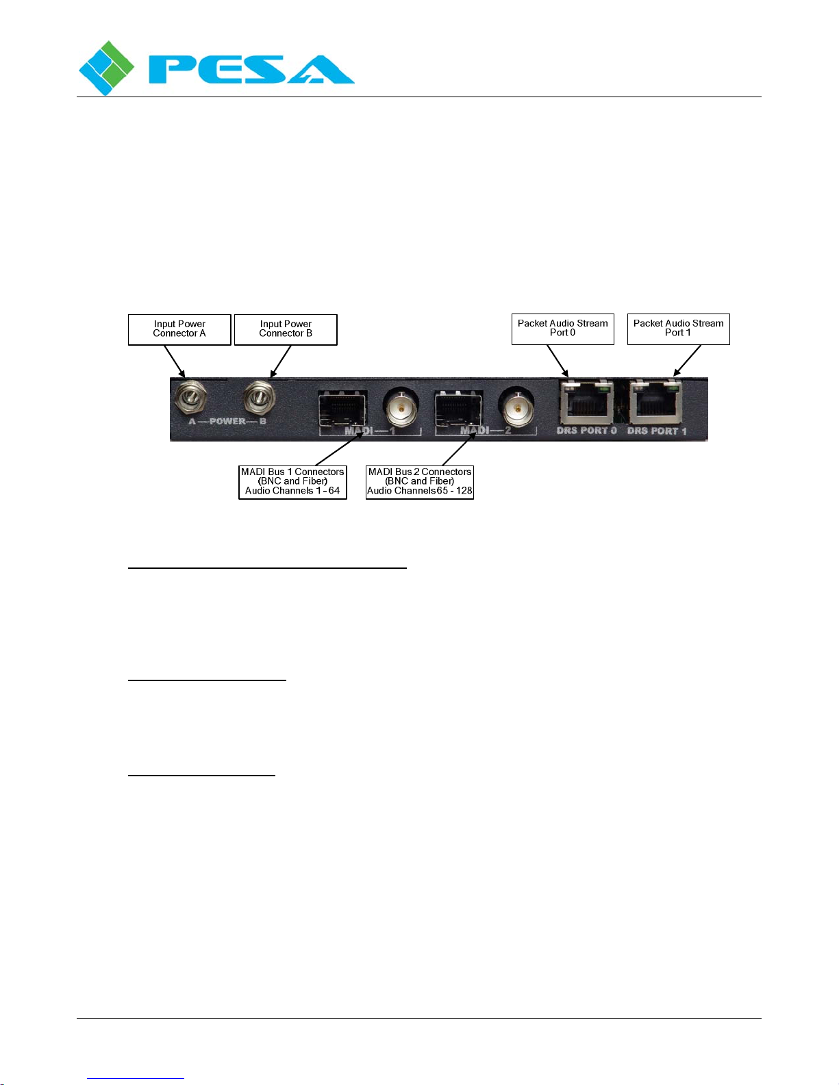
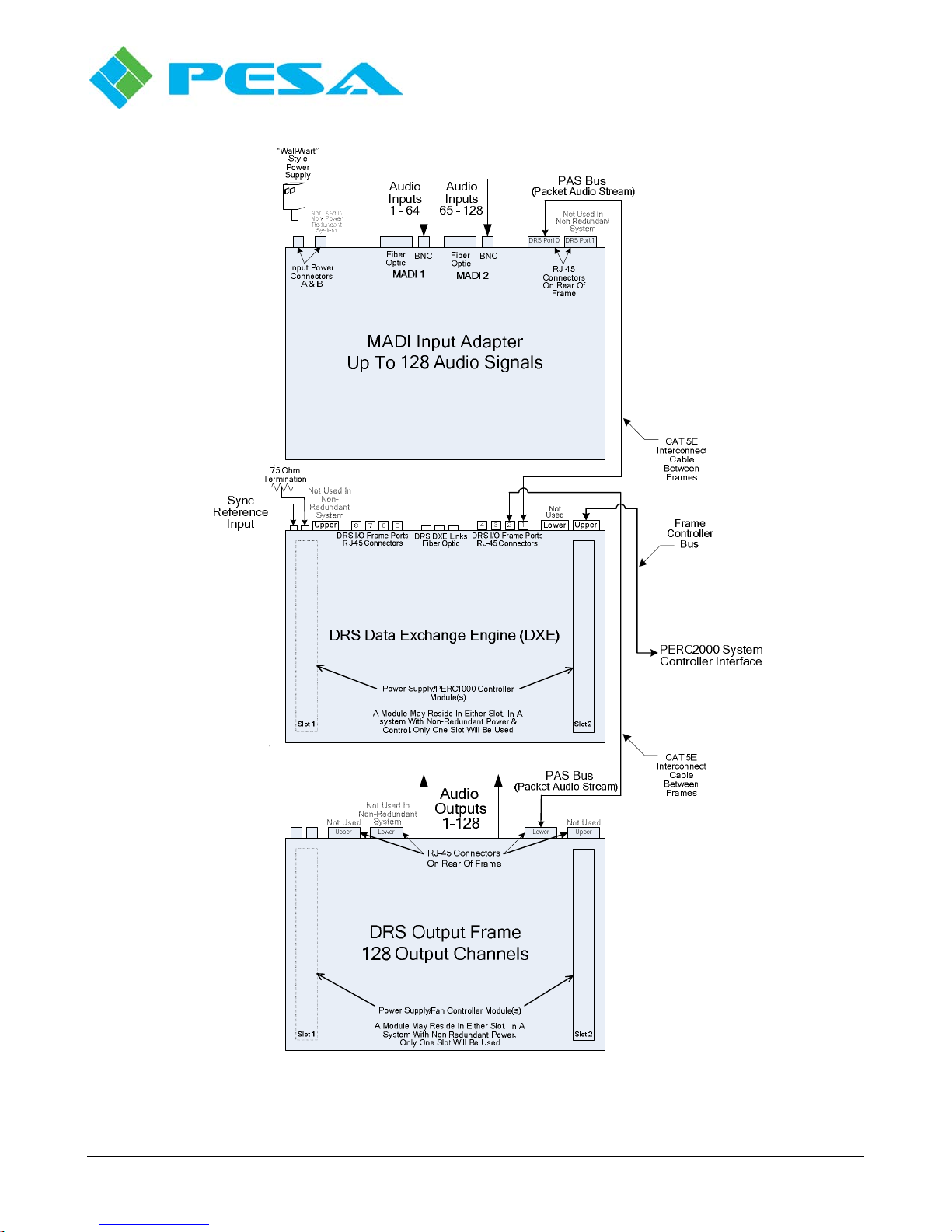
A block diagram of a basic 128 by 128 Router using a MADI input adapter is shown in Figure 2-3. If
both MADI 1 and MADI 2 inputs are used, the adapter supports 128 audio signals and the DRS audio
output frame provides 128 output signals. The DXE performs the data exchange between the MADI
adapter and the DRS output frame. A single run of common CAT5E cable (up to 100 Meters), fitted
with standard RJ-45 connectors on each end, between the MADI adapter and the DXE and the output
frame and the DXE completes the PAS bus interface and provides all interconnections between the
frames.
Each MADI adapter must be connected to the DXE I/O frame port connectors in numerical sequence by
the range of signal channels we wish to assign to it, beginning with frame port 1. In our example
configuration, the adapter containing a dedicated input channel block of MADI audio signals we wish to
assign as inputs 1 thru 128 is connected to frame port 1. Each frame port can interface with up to 128
channels from a single audio frame or adapter, so this frame fills the entire capacity of port 1 with
MADI input signals. In similar fashion, the DRS audio frame containing a dedicated channel block of
audio output signals we wish to assign as outputs 1 thru 128 is connected to frame port 2. This frame
fills the entire capacity of port 2 with output signals.
DXE frames must be connected to an in-house timing synchronization reference signal from the facility
sync generator. This reference pulse is used to synchronize system timing on all frames in the DRS
System, including the MADI adpaters.
Loop-thru BNC connectors for sync reference input and output are provided on the backplane of every
DXE frame. Remember, if the DXE frame is the only, or the last, piece of equipment on the chain the
open connector on the rear panel pair must be fitted with a 75 Ohm terminator load.
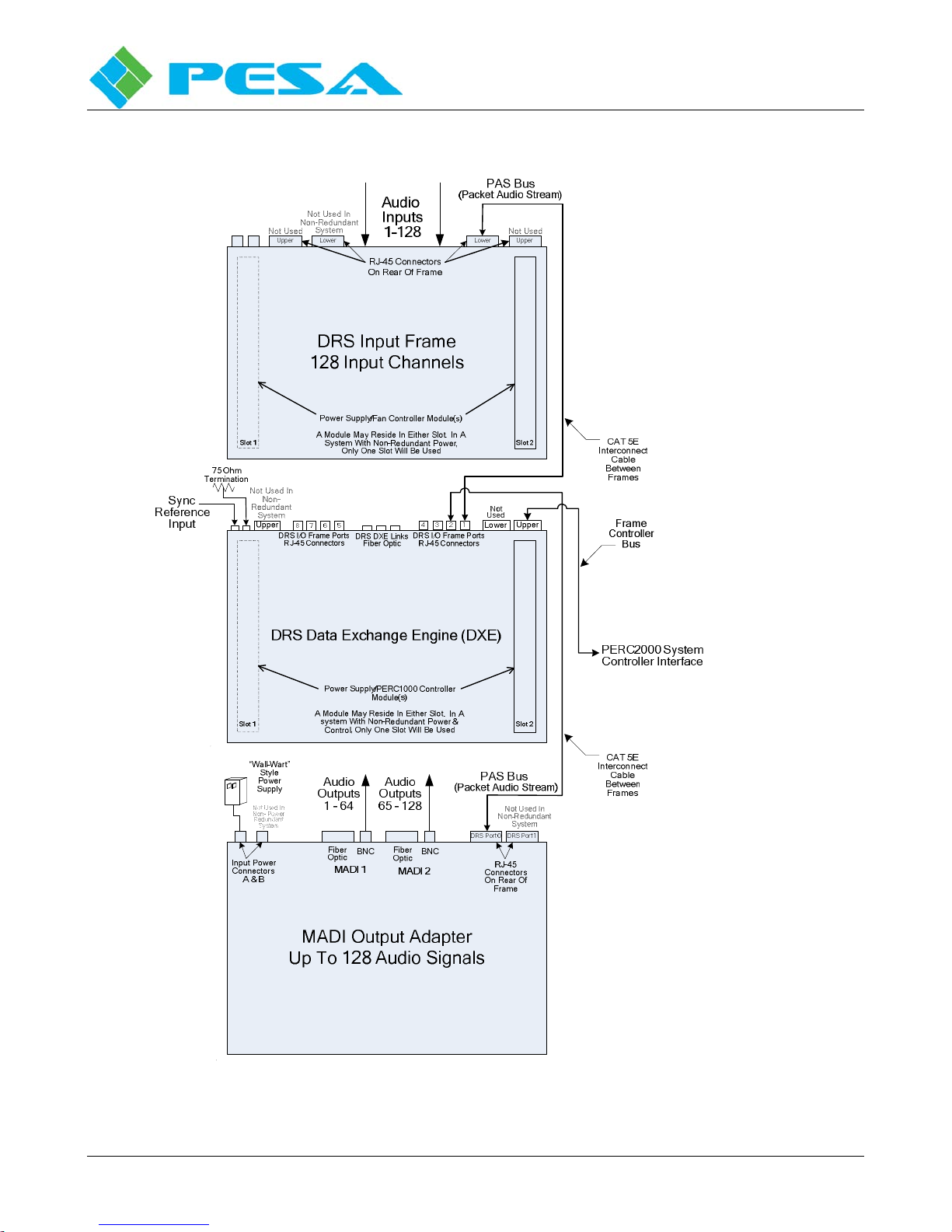
A basic 128 by 128 Router using a MADI output adapter is shown in Figure 2-4. If both MADI 1 and
MADI 2 inputs are used, the adapter provides 128 output signals and the DRS audio input frame
provides 128 input signals. Connection to the DXE frame is the same as outlined above.
Figure 2-5 illustrates a basic system using MADI adapters for both input and output data streams. These
examples illustrate that the MADI adapter is used just like an input or output frame in a DRS system.
MADI adapters will not function in systems with redundant DXE frames.

CHEETAH DRS SERIES MADI ADAPTER
Publication 81-9059-0597-0, Rev. B
September 2015
Proprietary Information of PESA 2-5
Figure 2-3 128 X 128 Non-Redundant Router System with MADI Inputs

CHEETAH DRS SERIES MADI ADAPTER
Publication 81-9059-0597-0, Rev. B
September 2015
Proprietary Information of PESA 2-6
FIGURE 2-4 128 X 128 Non-Redundant Router System with MADI Outputs

CHEETAH DRS SERIES MADI ADAPTER
Publication 81-9059-0597-0, Rev. B
September 2015
Proprietary Information of PESA 2-7
Figure 2-5 128 X 128 Non-Redundant Router System with MADI Inputs and Outputs

CHEETAH DRS SERIES MADI ADAPTER
Publication 81-9059-0597-0, Rev. B
September 2015
Proprietary Information of PESA 2-8
A block diagram of a 128X128 installation with power and frame controller redundancy is shown in
Figure 2-6.
Note that in order to provide power redundancy to each MADI module, a second “wall wart” type
power supply is required for each.
In addition to power redundancy, each Power Supply/PERC 1000 module in the DXE frame has
redundant frame controller capability as well. Notice that each controller module (Frame Controller
Bus 1 and 2) now has its own Ethernet port for interface with the PERC 2000 System Controller. These
are denoted as PERC 2000 System Controller Interface A and B in Figure 2-5. In order for frame
controller redundancy to be functional each module must be independently connected to the system
controller. There are various schemes on how to configure this, and each is discussed in detail in
Chapter 3 of the DRS technical manual.
The preceding examples illustrate typical hook-up of a MADI Adapter Module into various DRS
configurations. Additional examples, including redundant PAS bus and expanded I.O, multiple DXE
installations are provided in the DRS technical manual. Refer to Chapter 2 of the DRS manual for
further configuration examples.

CHEETAH DRS SERIES MADI ADAPTER
Publication 81-9059-0597-0, Rev. B
September 2015
Proprietary Information of PESA 2-9
MADI Input Adapter
Up To 128 Audio Signals
RJ-45
Connectors
On Rear Of
Frame
(Packet Audio Stream)
Audio
Inputs
1 - 64
CAT 5E
Interconnect
Cable
Between
Frames
DRS Port 0
PAS Bus
DRS Data Exchange Engine (DXE)
Slot 1 Slot 2
UpperLower
Upper 13 24
8 7 6 5
DRS DXE Links
Fiber Opt ic DRS I/O Frame Ports
RJ-45 Connectors
DRS I /O Frame Port s
RJ-45 Connectors
Power Supply/PERC1 Controller
Module(s)
A Module May Reside In Either Slot. In A
system With Non-Redundant Power &
Control, Only One Slot Will Be Used
CAT 5E
Interconnect
Cable
Between
Frames
(Packet Audio Stream)
DRS Port 1
Input Power
Connectors
A & B
Fiber
Optic BNC Fiber
Optic BNC
Audio
Inputs
65 - 128
75 Ohm
Termination
Sync
Reference
Input
MADI Output Adapter
Up To 128 Audio Signals
RJ-45
Connectors
On Rear Of
Frame
Audio
Outputs
1 - 64
DRS Port 0
PAS Bus
DRS Port 1
Input Power
Connectors
A & B
Fiber
Optic BNC Fiber
Optic BNC
“Wall-Wart”
Style
Power
Supply X2
Audio
Outputs
65 - 128
Frame Controller Bus 1
Frame Controller Bus 2
PERC2000 Syste
Controller Interface “A”
PERC2000 Syste
Controller Interface “B”
“Wall-Wart”
Style
Power
Supply X2
Figure 2-6 128 X 128 Router System with Redundant Power & Controller

CHEETAH DRS SERIES MADI ADAPTER
Publication 81-9059-0597-0, Rev. B
September 2015
Proprietary Information of PESA 3-1
Chapter 3 Installation
3.1 MADI
M
ODULE
I
NSTALLATION
O
PTIONS
MADI modules may be used stand-alone or mounted in a rack-mount chassis frame. When the rack-
mount frame is used, up to four modules may be installed to each rack frame.
3.2 M
OUNTING
A
MADI
M
ODULE
I
N
A
R
ACK
-M
OUNT
C
HASSIS
Each MADI module is secured into the rack-mount chassis by two captive thumb-screws located on the
front of the frame unit. Note that there are eight captive screws on the panel face – two for each of four
MADI modules.
Use the positioning tabs to align the MADI module in the rack frame. Slide the module forward and
tighten the thumb-screws to secure the module into the rack frame.
Figure 3-1 MADI Rack Frame - Module Installation
3.3 S
YSTEM
S
YNCHRONIZATION
It is imperative that the MADI compliant equipment and the DRS system be synchronized using the
same sync source!!!!!! Failure to provide synchronization will result in improper system operation.
3.4 C
ONNECTION
C
HECKLIST
Once each MADI module is installed, the associated system connections can be completed. The order
of completion of installation steps is not critical, however, DO NOT apply power to the module until the
MADI data stream and packet audio stream cables have been installed and their connections verified for
proper placement and accuracy.
If a MADI module is used in a standalone configuration,” connect the power output from the “wall
wart” power supply to either of the Power input connectors on the MADI module and plug the power
supply into a source of AC power.
If MADI modules are mounted in the optional rack frame, the power sled supplied with the frame is
used to power all installed MADI modules. Supply power to the rack mount supply, and connect a
power output from the common supply to each of the MADI modules installed in the rack.

CHEETAH DRS SERIES MADI ADAPTER
Publication 81-9059-0597-0, Rev. B
September 2015
Proprietary Information of PESA 4-1
Chapter 4 Operation
4.1 A
N
I
NTRODUCTION TO
T
HE
PESA
C
HEETAH
C
ONTROL
S
YSTEM
PESA’s MADI adapter operates as a component of the DRS audio routing system; there are no separate
operating controls for the MADI module. When incorporating MADI adapters into a DRS router, each
MADI module is essentially treated as any other DRS audio frame. Please refer to the Technical
Manual supplied with your DRS audio router system for complete information on configuration and set-
up of a DRS installation. The following brief introduction to the Cheetah control system is provided as
a reference, but the information presented here should be supplemented with the DRS manual.
Every Cheetah router installation – video matrix and DRS – has two control system components: frame
controllers and a system controller that interface through a communication protocol. A frame controller
card is located in every video routing chassis and every DRS DXE frame; and, as the name implies, is
the control component for functions within the particular frame in which it is installed. In a typical
Cheetah installation, there is only one system controller (two for redundancy) and it may be contained in
a video matrix frame or in a stand-alone chassis. The system controller interfaces with all frame
controllers, remote control panels and a host computer. Its function is to oversee operation of the entire
router installation through commands and communication with the individual frame controllers.
With DRS systems, PERC1000 (P1K) identifies the frame controller circuitry installed in each DXE
frame. P1K uses a 10/100 Ethernet protocol for communication and must be paired with the PESA
PERC2000 System Controller to complete the DRS control system requirements.
PERC2000 (P2K) is the name given collectively to the system controller circuit card assembly (CCA),
its associated board-resident firmware and a GUI application that resides and runs on a Microsoft
Windows™based PC platform. P2K provides routing control functions to the DRS router through the
P1K components; but can also be the master controller for other PESA routing and switching
components, such as a Cheetah Video Matrix Router. This is shown pictorially by Figure 4-1.
Figure 4-1 Example PESA Cheetah Control System

CHEETAH DRS SERIES MADI ADAPTER
Publication 81-9059-0597-0, Rev. B
September 2015
Proprietary Information of PESA 4-2
4.2 PERC2000
G
RAPHICAL
U
SER
I
NTERFACE
A major component of the P2K System Controller is the graphical user interface (GUI) software
application. This application must be installed on a Windows™ based PC that serves as a “host”
computer for the router installation. Complete instructions for installing the GUI application are
provided in the PERC2000 Technical Manual. All control and set-up operations for a DRS system are
done through the P2K GUI in conjunction with the P1K Frame Controller located in each DXE frame,
and the P2K System Controller hardware located external to the DRS router. System configuration data
is entered on the GUI screens to generate a configuration file, and may be immediately downloaded to
the frame and system controllers or may be saved as a data file for future use.
When the P2K GUI application is started on the host PC there are no configuration files loaded. The
user has three options from which to choose when the GUI application is first started:
1. Treat the screens as a “clean slate” and generate a new configuration file by entering hardware
and router configuration data for download to the controllers, or save the “new” file to a storage
media such as a hard drive of the host PC or other memory device
2. Load an existing configuration file from a previously saved and stored file
3. Upload the currently active configuration file stored in flash memory on the system controller
card
Either of the last two options allows the user to view or modify an existing configuration file.
Regardless of which option is chosen, as configuration data is entered or modified on the GUI screen, it
is stored by the GUI application on the host PC – and only on the host PC. Changes entered do not get
saved to a file, written to either the frame or system controller, or become active, until the operator
issues a command from the GUI to either save or download the configuration data.
In order to prepare a DRS system for operation, there are two distinct configuration procedures that
must be performed – hardware configuration and router configuration. Both types of configuration
procedures are accomplished by generating config files through screens of the P2K GUI and
downloading them to the controllers. Note that when a configuration file written using the P2K GUI is
saved to storage media, both DRS hardware and router configuration data is stored with the file; and can
be retrieved to the host PC for future modification or use. The act of saving a file does not download
the config data to either the frame controller or the system controller.
Designing and configuring a routing switcher system requires a thorough working knowledge of the
hardware components and the operational modes and functions available to the user. This discussion of
the P2K software application assumes the user has the knowledge of switching functions and
terminologies required to configure a system using the various commands and screens introduced in the
following paragraphs. The user will need clear understanding of the concepts of switching levels,
components, a reentry path, tie-lines, salvos, hardware strobes, etc. in order to make use of the following
discussions.

CHEETAH DRS SERIES MADI ADAPTER
Publication 81-9059-0597-0, Rev. B
September 2015
Proprietary Information of PESA 4-3
Be aware that system changes you can make through the commands and screens discussed in the
following paragraphs configure virtually all operational aspects of the system. Mistakes or erroneous
entries made in many of the following programming steps can cause serious problems ranging from
incorrect sources being switched to total shutdown of the entire system. Be sure you know exactly what
you want to do before you make changes to the system configuration.
4.3 H
ARDWARE AND
R
OUTER
C
ONFIGURATION
F
ILES
Hardware configuration is where the PERC1000 (P1K) Frame Controller in each DXE frame is
configured for the number and type of audio blocks under its control and a numerical input/output
channel range is assigned to each block. It is through the hardware configuration process that MADI
modules are configured into the DRS router. Consult the DRS Technical Manual for the configuration
procedure. Although hardware configuration functions are performed through the P2K GUI application,
and the data is stored as part of a saved system configuration file, the system controller has no real
intervention in this procedure.
In order for the system controller to operate, we must write a Router configuration file and load it into
controller memory. This file contains programming data for individual sources and destinations such as
where (frame and physical connector) each signal connects to the system, the type of signal and names
we wish to associate with each; as well as switching levels, components, source groups, destination
groups, and other system functions. It is through router configuration that audio signals available
through DRS can be paired with video signals in a video matrix frame for AFV or breakaway switching
as a group. In many installations, remote control panels are located at operator stations or consoles;
these are programmed through the router configuration file and allow an operator to control designated
functions of the router from a remote station. Virtually any routing function available through the P2K
control system can be applied to DRS audio signals.
A system configuration file containing both hardware and router configuration data may be named and
saved allowing it to be retrieved to the host PC for future modification or use. Multiple configuration
files may be written, stored and loaded as needed to allow quick access of different operational set-ups
for the routing system. Remember, however, that the act of generating or saving a file does not
download the configuration data to either the frame controller or the system controller.
4.4 MADI
I
NDICATOR
L
IGHTS
There are no operating controls for the MADI module; however, there are front panel indicator lights
which should be verified for proper operation.
An illustration of the MADI front panel and the status indicators is shown in Figure 4-2.

CHEETAH DRS SERIES MADI ADAPTER
Publication 81-9059-0597-0, Rev. B
September 2015
Proprietary Information of PESA 4-4
Figure 4-2 MADI Module Front Panel
4.5 MADI
M
ODULE
S
TATUS
L
IGHTS
There are 7 indicator lights on the front panel of each MAI module. The function of each is described in
the following paragraphs:
MADI ACTIVE There are two MADI Active indicators – labeled 1 and 2. These will light as an
indication of an active MADI interface on either input port 1 or 2, respectively.
LOAD ERROR The Load Error indicator should always be off during normal operation. When
power is first applied to the module, this indicator will light during system
strat-up and should extinguish a few seconds after initial power application.
Verify that the light is on at power-up and extinguishes. If the light remains lit
or lights during operation it indicates a problem with the internal processor.
DRS PORT There are four DRS Port indicators – two for each PAS Bus connection. Note
that each port has an indicator labeled ACT (active) and LNK (link). These
indicate Ethernet bus activity on each active (connected) port. Both indicators
should intermittently flash during normal system operation.

Table of contents