Petersen 128 Series User manual

128 Series Line Stop Plug
Instruction Manual
www.PetersenProducts.com
421 Wheeler Avenue, PO Box 340, Fredonia, Wisconsin 53201-0340, USA
Phone: (262) 692-3100 or 1-800-926-1926
Fax: (262) 692-2418 or 1-800-669-1434
Email: sales@petersenproducts.com

Revised 07/07/20 Petersen Products 128 Series Contents •ii
128 Series Line Stop Plug
WARNING
Read and understand before using Petersen Line Stop Plugs!
Failure to comply may result in property damage, serious injury or death!
These instructions must be available to all users. Train all personnel for proper use.
Contents
128 Series Line Stop Plug ......................................................................................................................................................................... ii
Important Safety Instructions.................................................................................................................................................................. 1
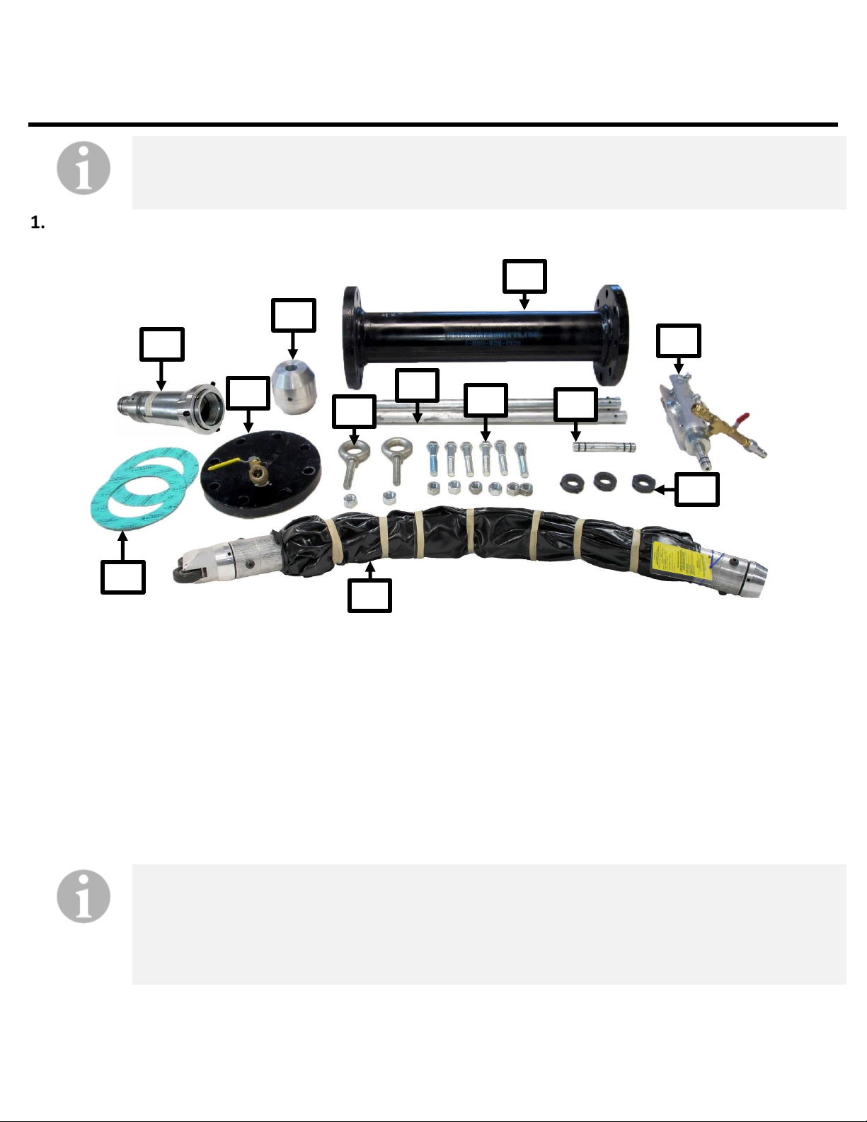
Pre-installation Inspection....................................................................................................................................................................... 2
Assembly Overview .................................................................................................................................................................................4
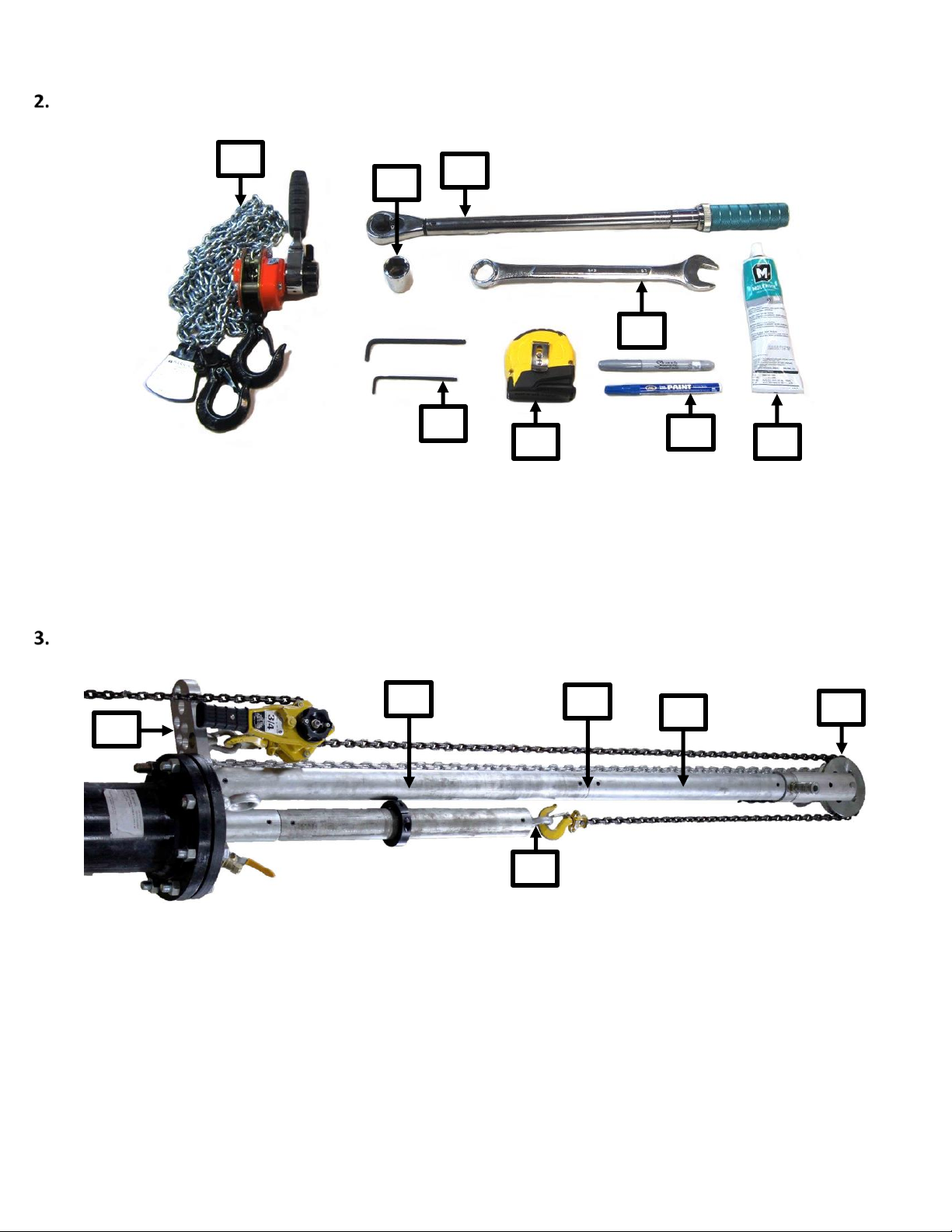
Hot Tap Insertion Tool Checklist .............................................................................................................................................................. 5
Overview.................................................................................................................................................................................................. 5
Tool List ...................................................................................................................................................................................................5
Launch Cylinder........................................................................................................................................................................................5
Torque Figures .........................................................................................................................................................................................5
Calculating the Head Pressure ................................................................................................................................................................. 6
Tapping the Pipe......................................................................................................................................................................................6
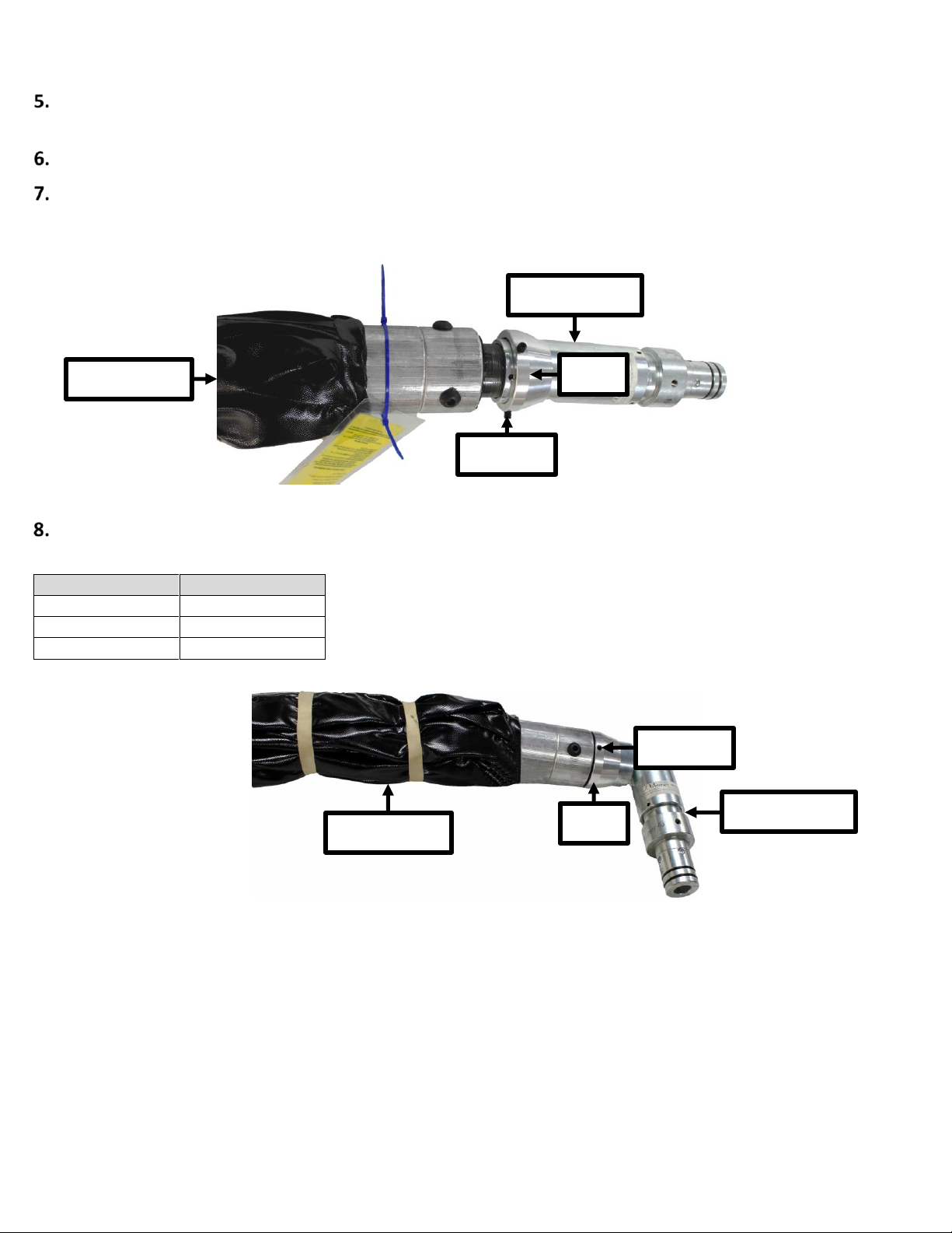
Attaching the Rotating Elbow Assembly .................................................................................................................................................. 7
Assembling the Launch Cylinder .............................................................................................................................................................. 9
Measuring the Assembly........................................................................................................................................................................ 10
Attaching the Main Stop Collar.............................................................................................................................................................. 12
Assembling the Insertion System........................................................................................................................................................... 13
Attaching the Insertion System.............................................................................................................................................................. 15
Inserting the Plug................................................................................................................................................................................... 18
Air Inflation Kit ...................................................................................................................................................................................... 20
Assembling the Air Inflation Kit ............................................................................................................................................................. 21
Deflating Air from the Line Stop Plugs ................................................................................................................................................... 23
Water Inflation Controller ..................................................................................................................................................................... 23
Overview................................................................................................................................................................................................ 23
Operating the Water Flow Totalizer:....................................................................................................................................................... 24
Assembling the Water Hoses and Pressure Monitoring Lines .................................................................................................................. 24
Inflating the Line Stop Plug with Water................................................................................................................................................... 26
Deflating Water from the Line Stop Plugs ............................................................................................................................................... 27
Removing the Line Stop Plug ................................................................................................................................................................. 29
Cleaning and Storing.............................................................................................................................................................................. 31

Petersen Products 128 Series Important Safety Instructions 1
Important Safety Instructions
Safety is Everyone’s Responsibility
WARNING
Extremely high forces are involved in many pipeline-plugging situations that may cause injury or even death. Forces
increase dramatically as pressure and pipe diameter increase. Extreme care is required to ensure the safe use of any
Line Stop Plug.
All line stop plugs must be anchored adequately.
Debris or protrusions into the pipeline can damage a seal or reduce the pressure rating. NEVER use a test pressure
greater than the capacity of the weakest pipe or component in the system.
Consult qualified personnel if you cannot calculate the risks or forces involved.
Do not exceed the pressures on the plug label.
Never use equipment when a failure could result in injury or significant property damage. Inflatable devices may not
be used as the primary protection for personnel downstream.
Because of
the many possible variables, these general instructions must be adapted by an engineerfor
each specific
project. Instructions and training must be provided to all plug users and workers on thejob.
Personnel Safety
CAUTION
Keep all personnel away from the plug end area.
Wear required PPE including but not limited to eye protection, helmet, hearing protection.
Follow all confined space safety controls. Confined space authorization, air monitor, and ventilation may be
required.
Safety Inspections
Thoroughly inspect the line stop plug for abrasions, cuts, or physical damage. Clean the plug if required.
If outside a pipe, do not inflate a line stop plug greater than 5 psi or above 5% of rated pressure.
Gather all required tools. Have all personnel ready when installing and removing any type of line stop plug.
Verify that the air line connections and hoses are not damaged or leaking.
Use two accurate calibrated pressure gauges to measure the pipeline head pressure.
Prepare to equalize pressure on both sides of the line stop plug before installation and removal.
Use two accurately calibrated pressure gauges that agree to monitor the inflation pressure.
Verify that the pipeline flow is stopped.
Contact the project engineer or Petersen if needed. Safety is the highest priority.

Petersen Products 128 Series Pre-installation Inspection 2
Pre-installation Inspection
Safety
Survey the work area for unsafe conditions. Verify that each person has read the Product Labels, Scope of
Work, and instructions developed specific to the project.
Verify the Line Stop Plug and Launch System components are complete.
1. Rotating Elbow
7. Launch Cylinder
2. Packing Seal
8. Inflation Ram Coupling
3. Centering Anchor
9. Inflation Ram Pulley Assembly
4. Eyebolts
10. Stop Collars
5. Inflation Ram Sections
11. Flange Gaskets
6. Flange Bolts
12. Line Stop Plug
NOTE
Petersen recommends inspecting the line stop plugs after every use. Covers can be damaged when inserting
into a hot tap. Often line stop plugs can be refurbished and recertified by Petersen Products to like-new
condition or set interval to match quality standards.
Contact Petersen to confirm the suitability of the line stop plug if needed.
1
3
5
6
7
11
4
8
10
9
2
12

Petersen Products 128 Series Pre-installation Inspection 3
Gather all necessary equipment and tools. Refer to Hot Tap Insertion Tool Checklist.
1. Ratchet Puller
5. Tape Measure
2. Socket
6. Wrench
3. Torque Wrench
7. Marker
4. Allen Wrench
8. O-Ring Lubricant
If using a Retraction System, verify that all Retraction System components are complete.
10. Ram Removal Plate
13. Ram Section, 36 inches
11. Ram Section, 24 inches
14. Pull Block Assembly
12. Ram Coupling
15. Pulley Assembly
1
2
3
6
8
5
7
4
10
11
12
14
15
13

Petersen Products 128 Series Assembly Overview 4
Assembly Overview
Launch Cylinder
Tapping Valve
Inflation Hose
Pressure Monitor Hose
Rachet Puller
Packing Seal
Rotating Elbow
Line Stop Plug
Directional Shoe
Inflation Ram Pulley

Petersen Products 128 Series Hot Tap Insertion Tool Checklist 5
Hot Tap Insertion Tool Checklist
WARNING
Read and understand instructions before using Petersen Inflatable devices. Failure to comply may result in
property damage, serious injury, or death.
Overview
The Petersen Hot Tap Insertion System can be used on almost any size pipeline or system. Use the tool list as a guideline.
Each job may require tools above and beyond what is listed.
Tool List
Ratchet Puller
For inserting and securing the line stop plug and for retraction with retraction kit.
Marker or Paint Stick
For marking on steel, fabric, or painted surfaces.
Tape Measure
To set insertion depth on Inflation Ram or Bundling Sleeve strap lengths.
O-Ring Lubricant
Inflation Ram and Packing Seal O-Rings.
Allen Wrench 1/8"
Set Screws for 1 inch and 1-7/8-inch diameter Inflation Ram.
Allen Wrench 3/32"
Set Screws for 1-1/2-inch Inflation Ram.
Allen Wrench 3/16"
Set Screws for 2-1/2-inch Inflation Ram, 1-inch stop collar, centering guides.
Allen Wrench 1/4"
Stop Collar for 1-7/8-inch diameter Inflation Ram.
Allen Wrench 5/16"
Stop Collar for 2-1/2-inch Inflation Ram.
Pipe Wrench
Attaching NPT Launch Cylinder and Packing Seal.
Pipe Thread Sealant
Attaching NPT Launch Cylinder and Packing Seal.
Launch Cylinder
Torque Wrench & Socket
Match the values listed in the table below for the launch cylinder.
Wrench
For reaction force against Torque Wrench (match socket size).
Torque Figures
Note: Sequence the torque in a star pattern. Complete the pattern three times 30%, 70%, 100% to the sequence.
Torque Figures
Class 150 Flanges
Class 300 Flanges
Size
Bolt
Wrench
Torque
Bolt
Wrench
Torque
3
5/8"
15/16"
16 ft·lb
4
5/8"
15/16"
110 ft·lb
5
3/4"
1-1/8"
195 ft·lb
6
3/4"
1-1/8"
195 ft·lb
3/4"
1-1/8"
195 ft·lb
8
3/4"
1-1/8"
195 ft·lb
7/8"
1-5/16"
310 ft·lb
10
7/8"
1-5/16"
310 ft·lb
1"
1-1/2"
465 ft·lb
12
7/8"
1-5/16"
310 ft·lb
1-1/8"
1-11/16"
685 ft·lb
14
1"
1-1/2"
465 ft·lb
1-1/8"
1-11/16"
685 ft·lb
16
1"
1-1/2"
465 ft·lb
1-1/4"
1-7/8"
960 ft·lb
18
1-1/8"
1-11/16"
605 ft·lb
20
1-1/8"
1-11/16"
605 ft·lb
24
1-1/4"
1-7/8"
960 ft·lb
30
1-1/4"
1-7/8"
960 ft·lb

Petersen Products 128 Series Calculating the Head Pressure 6
Calculating the Head Pressure
Calculate the required head pressure to confirm effective and safe plugging. Follow these guidelines to calculate the head
pressure:
F = P * S (2) F = force on the plug, P = pipeline pressure, S = cross-sectional area
•Force F on the plug is the plug slipping force.
•Pressure P measured as water column height must be converted to a force over area format for the equation above.
The cross-sectional area S is determined by:
•S = π r 2
•Where π = 3.14159 and r (radius) = ½ the pipe inside diameter.
Example:
•Water column 10 m (32.8 ft) high, converts to a back pressure of 98.0 kPa (14.5 psi).
The configuration or liquid surface area does not affect pressure, only elevation. The pressure is multiplied by the
pipe/plug diameter to arrive at the plug slipping force.
•Pressures exerted on a plug are the same for liquid, water, or air.
•68.9 kPa (10 psi) of water = 98.9 kPa (10 psi) air
•Pressures from gasses (e.g., air, nitrogen) are compressible and more dangerous than water.
•Gas will expand to its original atmospheric volume upon release. Discharging a slipping plug will have much greater
force.
Tapping the Pipe
NOTE
Verify that the flow in pipe is stopped before making the hot tap.
Install the the Saddle or Sleeve, according to manufacturer. Position the Saddle or Sleeve so that when the Line Stop Plug is
inserted, it will not be damaged by sharp edges or protrusions.
Install the Tapping Valve according to manufacturer. Remove the blind flange if present.
NOTE
Inspect for leaks BEFORE using the Hot Tap Drill Equipment. Use the Test Port on the hot tap sleeve, nozzle or
valve. Once the drill is used the valve will be pressurized. Fix all leaks before using the drill.
Open the Tapping Valve completely.
Use the Hot Tapper Drill Adapter to the Tapping Valve. See the Hot Tap Drill manufacturer for detailed operation and
maintenance information.

Petersen Products 128 Series Attaching the Rotating Elbow Assembly 7
Drill the Hot Tap Hole into the pipeline.
Remove the Hot Tapper Drill. Close the Tapping Valve.
If possible, open the Chip Valve on the Hot Tapper Drill Adapter, to allow chips to be washed out and to provide differential
pressure to capture the coupon/cut-out.
Attaching the Rotating Elbow Assembly
The Rotating Elbow Assembly is available with Thread and Set Screw type connections for the Inflation Ram Adapter.
Inspect the O-Rings for any possible physical damage. Petersen recommends ordering multiple O-Rings.
Use the Allen Wrench to loosen the Set Screws on the Cone.
Apply O-Ring lubricant to the Ram End on the Rotating Elbow Assembly.
Remove the End Cap and apply Thread Sealant to the threads on the end of the Line Stop Plug.
Chip Valve
Removal Cone
Line Stop Plug
Rotating Elbow
Set Screw
Ram End
Directional Shoe
Wheel

Petersen Products 128 Series Attaching the Rotating Elbow Assembly 8
Connect the Rotating Elbow to the Line Stop Plug. Tighten 1-½ to 2-½ turns past HAND tight. Verify that the Rotating Elbow
is oriented to bend in the same direction as the directional shoe.
Tighten the Set Screws on the Rotating Elbow to secure in position on the Line Stop Plug.
The bend of the Rotating Elbow should follow the natural curve of the Line Stop Plug.
Note: The plug will tend to follow the large diameter wheel on the Directional Shoe when entering the pipeline. The elbow
direction should match.
Slide the Cone over the Line Stop Plug. Use the Allen Wrench to tighten the Set Screws. Remove and store the tag in a safe
space.
Screw Size
Torque
#10
30 in·lb
1/4″
76 in·lb
3/8″
276 in·lb
Line Stop Plug
Rotating Elbow
Cone
Cone
Rotating Elbow
Set Screw
Set Screw
Line Stop Plug

Petersen Products 128 Series Assembling the Launch Cylinder 9
Assembling the Launch Cylinder
Replace the Gasket each time the Launch Cylinders are assembled.
Verify that the Valves are oriented at the bottom for draining process fluid when the job is complete.
Close each Valve.
Insert the Gasket between the Flanges on each Launch Cylinder.
Bolt each Launch Cylinder section together. Use a star pattern for balanced torque. Complete the pattern three times 30%,
70%, 100% to the torqueing sequence. See Torque Figures on page 5.
Launch Cylinder
Bolt
Valve
Valve
Gasket
Launch Cylinder

Petersen Products 128 Series Measuring the Assembly 10
Measuring the Assembly
NOTE
Write the measurement in the boxes to use later.
Measure the length of the Rotating Elbow to the centerline of the pivot when positioned at a 90° angle.
M1
Measure the distance from the top flange of the Tapping Valve to the top of the OD of the pipe. Determine the radius of
the pipe. Add M2 to the radius M3 to determine M4.
Note: M3 is the distance from the OD of the pipe to the centerline. Find M3 by dividing the OD by 2.
Note: M2+M3=M4
M2
M3
M4
Rotating Elbow
Measure M2
Pipe
Tapping Valve
Measure M3
Measure M1

Petersen Products 128 Series Measuring the Assembly 11
Measure or calculate the total length of the fully assembled Inflation Ram section. Fit the sections together if needed.
M5
Combine the length of the Launch Cylinders, the width of the Packing Seal, and the thickness of the Ram Removal Plate
(if the Retraction System is used) to determine M6.
M6
Measure M5
Launch Cylinder
Measure M6
Ram Removal Plate
(optional)
Packing Seal
Measure M6
Measure M6

Petersen Products 128 Series Attaching the Main Stop Collar 12
Attaching the Main Stop Collar
NOTE
Position the Main Stop Collar so that the Plug and Rotating Elbow will insert to in the center of the pipe.
Find the total length the assembly. M4 + M6 –M1 + 1/8 inches (1 gasket) = M7
Subtract the length of the assembly from the Ram length. M5 –M7 = M8
Attatch the Main Stop Collar at M8. Tighten the Socket Head Cap Screws to secure the Main Stop Collar in place.
Collar
Screw Size
Allen Wrench
Torque
1”& 1-1/2”
1/4”
3/16”
14 ft·lb
1-7/8”
5/16″
1/4”
27 ft·lb
2-1/2”
3/8”
5/16”
47 ft·lb
M5
M7
M8
Inflation Ram Section
Measure M8
Main Stop Collar
Socket Head Cap Screw

Petersen Products 128 Series Assembling the Insertion System 13
Assembling the Insertion System
NOTE
The Insertion System can be assembled in two methods:
•If height clearance is sufficent, insert the Ram in one increment.
•If height restriction is an issue, use an Initial Stop Collar and insert the Ram in multiple increments.
Apply O-Ring lubricant to the O-Rings on the Inflation Ram Couplings. Connect each ram section together.
Tighten the Set Screws to secure each Ram section in place. See figure below for torque.
Screw Size
Torque
#10
30 in·lb
1/4″
76 in·lb
3/8″
276 in·lb
3.1If height clearance is sufficent, fully assemble the Inflation Ram. Attach the Packing Seal and Ram Assembly End to the
Inflation Ram.
Note: Apply O-Ring lubricant to the Packing Seal if needed.
Inflation Ram Section
Main Stop Collar
Set Screw
Coupling
Main Stop Collar
Ram End Assembly
Packing Seal

Petersen Products 128 Series Assembling the Insertion System 14
3.2If height restriction is an issue:
•Separate the Inflation Ram section with the Main Stop Collar from the rest of the Inflation Ram.
•Remove as many sections as required to fit in with the available space.
•Attach the Packing Seal and Ram End Assembly to the remaining sections of the Inflation Ram, which will be the
bottom section(s).
•Attach an Initial Stop Collar approximately 6” below the Ram End Assembly, but above the Packing Seal.
Note: Apply O-Ring lubricant to the Packing Seal if needed.
4. Slide a Gasket and the Centering Anchor on the Ram below the Packing Seal. Position the Centering Anchor M3 –M1
distance from the end of the Ram. Tightnen the set screws. See figure below if needed.
Note: M3 is the distance from the OD of the pipe to the centerline. Find M3 by dividing the OD by 2.
Screw Size
Torque
#10
30 in·lb
1/4″
76 in·lb
3/8″
276 in·lb
M3 –M1
Ram End Assembly
Initial Stop Collar
Packing Seal
Main Stop Collar
Set Screw
Measure M3 –M1
Centering Anchor
Gasket
Main Stop Collar

Petersen Products 128 Series Attaching the Insertion System 15
5. Apply O-Ring lubricant to the O-Rings on the Rotating Elbow Assembly. Attach the Rotating Elbow to the end of the
Inflation Ram. Tighten the Set Screws to secure the Inflation Ram to the Rotating Elbow.
Screw Size
Torque
#10
30 in·lb
1/4″
76 in·lb
3/8″
276 in·lb
Attaching the Insertion System
NOTE
The Insertion System can be attached in two methods:
•If height clearance is sufficent, insert the Ram in one increment.
•If height restriction is an issue, use an Initial Stop Collar and insert the Ram in multiple increments.
Use a Marker or Paint Stick on the Inflation Ram to mark the orientation of the Rotating Elbow and Plug. The Orientation
Line should align with the curvature of the Plug and direction of insertion. Use the mark as a guide when lowering the Plug
into the Pipe.
Note: Use the Orientation Line and and measurments to verify the Plug insertes in the center of the Pipe.
Insert the Plug and the Inflation Ram into the Launch Cylinder. Hand-tighten the bolts to secure the Packing Seal to the
Launch Cylinder.
Note: The rubber bands must remain on the Line Stop Plug for effective insertion.
Add the Eyebolts to the Packing Seal, positioned 180° apart. Orient the Eybolts so that they are parallel, not perpindicular.
See image on Page 16 if needed.
If using the Retraction System, attach the Ram Removal Plate to the Packing Seal. Hand-tighten the bolt to secure the Ram
Removal Plate to the Packing Seal.
Set Screw
Rotating Elbow
Line Stop Plug
Main Stop Collar
Orientation Line

Petersen Products 128 Series Attaching the Insertion System 16
Tighten each bolt. Use a star pattern for balanced torque. Complete the pattern three times 30%, 70%, 100% to the
torquing sequence.
Note: See Torque Figures on page 5.
NOTE
Do not lift the assembly by the Ram End. The load could slide and physical damage could occur.
Pull the Line Stop Plug into the Launch Cylinder so that no part extend past the end of the Launch Cylinder. Attach a Stop
Collar to the Inflation Ram flush with the top of the Packing Seal to secure the Line Stop Plug in position.
If installing vertically, connect the hoist end to the Eyebolts on the Packing Seal. If installing horizontally, wrap slings
around the Launch Cylinder.
Use a hoist to lift the Launch Cylinder assembly on the flange of the Tapping Valve. Install a gasket in between the Tapping
Valve and the Launch Cylinder.
Eyebolt
Eyebolt
Launch Cylinder
Orientation Line
Bolt
Ram Removal Plate
(optional)
Packing Seal
Eye nut
Orientation

Petersen Products 128 Series Attaching the Insertion System 17
Verify that the Inflation Ram Assembly, Launch Cylinders, and Line Stop Plug are alligned with the direction of the plug
insertion. Verify each valve on each Launch Cylinder is closed.
Tighten the bolts to secure the Assembly in place. Use a star pattern for balanced torque. Complete the pattern three
times 30%, 70%, 100% to the torquing sequence. See Torque Figures on page 5.
Attach the ratchet puller. Loop the the chain over the Inflation Ram. Connect each end to the Eyebolts.
Insert the Gauge on the quick connect port on the Packing Seal to monitor the head pressure.
Gauge
Rachet Puller
Eyebolt
Quick
Connect Port
Inflation Ram
Valve
Valve
Gasket

Petersen Products 128 Series Inserting the Plug 18
Inserting the Plug
CAUTION
The Inflation Ram may rise until the centering guide contacts the packing seal.
Open the Tapping Valve.
Inspect the Gauge Pressure. Inspect the Head Pressure on the Gauge on the Packing Seal. If the Pipeline is filled with water,
add 0.433 psi per foot the Gauge is above the Pipeline invert.
Note: The actual head pressure should not be greater than half the rating of the Plug.
Use the Rachet Assembly to lower the Inflation Ram and Plug into the pipe. Loosen the Stop Collar that is against the
Packing Seal to allow the Line Stop Plug to lower down into the pipe.
NOTE
The Insertion System can be attached in two methods:
•If height clearance is sufficent, insert the Ram in one increment.
•If height restriction is an issue, use an Initial Stop Collar and insert the Ram in multiple increments.
If the Inflation Ram is already fully assembled lower the untill the Main Stop Collar reaches the Packing Seal. Use O-Ring
lubricant if needed. Skip to Step 5.
Note: Maintain correct plug orientation during insertion.
Tapping Valve
Packing Seal
Main Stop Collar
Rachet Puller
Table of contents