PEWA BENNING MM 6 User manual

Bedienungsanleitung
Operating manual
Notice d‘emploi
Gebruiksaanwijzing
Instrucciones de servicio
Bruksanvisning
Istruzioni d’uso
BENNING MM 6
Elektrotechnik & Elektronik GmbH & Co. KG
Münsterstraße 135 - 137
D - 46397 Bocholt
+49 (0) 2871 - 93 - 0 • Fax ++49 (0) 2871 - 93 - 429
Bild 1: Gerätefrontseite
Fig. 1: Front tester panel
Fig. 1: Panneau avant de l‘appareil
Fig. 1: Voorzijde van het apparaat
Fig. 1: Parte frontal del equipo
Fig. 1: Framsida
ill. 1: Lato anteriore apparecchio
08/ 2004
BENNING MM 6
08/ 2004
BENNING MM 6
Bild 2: Gleichspannungsmessung
Fig. 2: Direct voltage measurement
Fig. 2: Mesure de tension continue
Fig. 2: Meten van gelijkspanning
Fig. 2: Medición de tension contínua
Fig. 2: Likspänningsmätning
ill. 2: Misura tensione continua
Bild 3: Wechselspannungsmessung
Fig. 3: Alternating voltage measurement
Fig. 3: Mesure de tension alternative
Fig. 3: Meten van wisselspanning
Fig. 3: Medición de tensión alterna
Fig. 3: Växelspänningsmätning
ill. 3: Misura tensione alternata
Bild 5: Wechselstrommessung
Fig. 5: AC current measurement
Fig. 5: Mesure de courant alternatif
Fig. 5: Meten van wisselstroom
Fig. 5: Medición de corriente alterna
Fig. 5: Växelströmsmätning
ill. 5:
Misura corrente alternata
Bild 4: Gleichstrommessung
Fig. 4: DC current measurement
Fig. 4: Mesure de courant continu
Fig. 4: Meten van gelijkstroom
Fig. 4: Medición de corriente contínua
Fig. 4: Likströmsmätning
ill. 4: Misura corrente continua

08/ 2004
BENNING MM 6
08/ 2004
BENNING MM 6
08/ 2004
BENNING MM 6
08/ 2004
BENNING MM 6
Bild 12: Sicherungswechsel
Fig. 12: Fuse replacement
Fig. 12: Remplacement des fusibles
Fig. 12: Vervanging van de smeltzekeringen
Fig. 12: Cambio de fusible
Fig. 12: Säkringsbyte
ill. 12: Sostituzione fusibile
Bild 14: Aufstellung des BENNING MM 6
Fig. 14: Standing up the BENNING MM 6
Fig. 14: Installation du BENNING MM 6
Fig. 14: Opstelling van de multimeter BENNING MM 6
Fig. 14: Colocación del BENNING MM 6
Fig. 14: Instrumentstöd BENNING MM 6
ill. 14: Posizionamento del BENNING MM 6
Bild 13: Aufwicklung der Sicherheitsmessleitung
Fig. 13: Wrapping up the safety test leads
Fig. 13: Enroulement du câble de mesure de sécurité
Fig. 13: Wikkeling van veiligheidsmeetsnoeren
Fig. 13: Arrollamiento de la conducción protegida de medición
Fig. 13: Placering av säkerhetsmätsladdar
ill. 13: Avvolgimento dei cavetti di sicurezza
Bild 9: Kapazitätsmessung
Fig. 9: Capacity Testing
Fig. 9: Mesure de capacité
Fig. 9: Capaciteitsmeting
Fig. 9: Medición de capacidad
Fig. 9: Kapacitansmätning
ill. 9: Misura di capacità
Bild 8: Durchgangsprüfung mit Summer
Fig. 8: Continuity Testing with buzzer
Fig. 8: Contrôle de continuité avec ronfleur
Fig. 8: Doorgangstest met akoestisch signaal
Fig. 8: Control de continuidad con vibrador
Fig. 8: Genomgångstest med summer
ill. 8: Prova di continuità con cicalino
Bild 10: Frequenzmessung
Fig. 10: Frequency measurement
Fig. 10: Mesure de fréquence
Fig. 10: Frequentiemeting
Fig. 10: Medición de frecuencia
Fig. 10: Frekvensmätning
ill. 10: Misura di frequenza
Bild 11: Batteriewechsel
Fig. 11: Battery replacement
Fig. 11: Remplacement de la pile
Fig. 11: Vervanging van de batterijen
Fig. 11: Cambio de pila
Fig. 11: Batteribyte
ill. 11: Sostituzione batterie
Bild 6: Widerstandsmessung
Fig. 6: Resistance measurement
Fig. 6: Mesure de résistance
Fig. 6: Weerstandsmeting
Fig. 6: Medición de resistencia
Fig. 6: Resistansmätning
ill. 6: Misura di resistenza
Bild 7: Diodenprüfung
Fig. 7: Diode Testing
Fig. 7: Contrôle de diodes
Fig. 7: Diodecontrole
Fig. 7: Verificación de diodos
Fig. 7: Diod-test
ill. 7: Prova diodi

10/ 2004
BENNING MM 6
1
Bedienungsanleitung
BENNING MM 6
Digital-Multimeter zur
- Gleichspannungsmessung
- Wechselspannungsmessung
- Gleichstrommessung
- Wechselstrommessung
- Widerstandsmessung
- Diodenprüfung
- Durchgangsprüfung
- Kapazitätsmessung
- Frequenzmessung
Inhaltsverzeichnis
1. Benutzerhinweise
2. Sicherheitshinweise
3. Lieferumfang
4. Gerätebeschreibung
5. Allgemeine Angaben
6. Umgebungsbedingungen
7. Elektrische Angaben
8. Messen mit dem BENNING MM 6
9. Instandhaltung
10. Anwendung des Gummi-Schutzrahmens
1. Benutzerhinweise
Diese Bedienungsanleitung richtet sich an
- Elektrofachkräfte und
- elektrotechnisch unterwiesene Personen
Das BENNING MM 6 ist zur Messung in trockener Umgebung vorgesehen. Es darf
nicht in Stromkreisen mit einer höheren Nennspannung als 1000 V DC und 750 V
AC eingesetzt werden (Näheres hierzu im Abschnitt 6. “Umgebungsbedingungen”).
In der Bedienungsanleitung und auf dem BENNING MM 6 werden folgende
Symbole verwendet:
Dieses Symbol weist auf elektrische Gefahr hin.
Dieses Symbol weist auf Gefährdungen beim Gebrauch des
BENNING MM 6 hin. (Dokumentation beachten!)
Dieses Symbol auf dem BENNING MM 6 bedeutet, dass das Gerät
schutzisoliert (Schutzklasse II) ausgeführt ist.
Dieses Symbol auf dem BENNING MM 6 weist auf die eingebauten
Sicherungen hin.
Dieses Symbol erscheint in der Anzeige für eine entladene
Batterie.
Dieses Symbol kennzeichnet den Bereich „Diodenprüfung“.
Dieses Symbol kennzeichnet den Bereich “Durchgangsprüfung”.Der
Summer dient der akustischen Ergebnisausgabe.
Dieses Symbol kennzeichnet den Bereich “Kapazitätsprüfung”.
(DC) Gleichspannung.
(AC) Wechsel- Spannung oder Strom.
Masse (Spannung gegen Erde).

10/ 2004
BENNING MM 6
2
2. Sicherheitshinweise
Beispiel für einen Sicherheitshinweis:
Elektrische Gefahr!
Beachten Sie die Sicherheitshinweise!
Bevor Sie das BENNING MM 6 benutzen, lesen Sie bitte die Bedienungsan-
leitung sorgfältig. Beachten Sie die Sicherheitshinweise in der Bedienungsan-
leitung. Damit schützen Sie sich vor Unfällen und das BENNING MM 6 vor
Schäden.
3. Lieferumfang
Zum Lieferumfang des BENNING MM 6 gehören:
3.1 ein Stück BENNING MM 6,
3.2 ein Stück Sicherheitsmessleitung, rot (L = 1,4 m; Spitze Ø = 4 mm),
3.3 ein Stück Sicherheitsmessleitung, schwarz (L = 1,4 m; Spitze Ø =
4 mm),
3.4 ein Stück Gummi-Schutzrahmen,
3.5 ein Stück Kompakt-Schutztasche,
3.6 eine 9-V-Blockbatterie und zwei unterschiedliche Sicherungen (zur Erst-
bestückung im Gerät eingebaut),
3.7 eine Bedienungsanleitung.
Hinweis auf Verschleißteile:
- Das BENNING MM 6 enthält Sicherungen zum Überlastschutz:
Ein Stück Sicherung Nennstrom 10 A flink (500 V), D = 6,35 mm, L = 32
mm und ein Stück Sicherung Nennstrom 1 A flink (500 V), D = 6,35 mm,
L = 32 mm.
- Das BENNING MM 6 wird durch eine eingebaute 9-V-Blockbatterie
(IEC 6 LR 61) gespeist.
- Die oben genannten Sicherheitsmessleitungen ATL 2 (geprüftes
Zubehör) entsprechen CAT III 1000 V und sind für einen Strom von 10 A
zugelassen.
4. Gerätebeschreibung
siehe Bild 1: Gerätefrontseite
Die in Bild 1 angegebenen Anzeige- und Bedienelemente werden wie folgt
bezeichnet:
Digitalanzeige, für den Messwert, die Bargraphanzeige und die Anzeige
der Bereichsüberschreitung,
Polaritätsanzeige,
Batterieanzeige, erscheint bei entladener Batterie,
RANGE-Taste, Umschaltung automatischer/ manueller Messbereich
HOLD-Taste,
~Hz-Taste, im ACV und ACA-Bereich Umschaltung in Frequenzanzeige
Taste (blau), für Gleichspannung/ -Strom (DC) bzw. Wechselspannung/ -
Strom (AC), Widerstandsmessung bzw. Diodenprüfung, Frequenzmessung
bzw. Drehzahlmessung (RPM)
Drehschalter, für Wahl der Messfunktion,
Buchse (positive1), für V, Ω, Hz
COM-Buchse, gemeinsame Buchse für Strom-, Spannungs-, Widerstands-,
Frequenz-, Kapazitätsmessungen, Durchgangs- und Diodenprüfung,
Buchse (positive), für mA-Bereich, für Ströme bis 400 mA,
Buchse (positive), für 10 A-Bereich, für Ströme bis 10 A,
Gummi-Schutzrahmen
1
) Hierauf bezieht sich die automatische Polaritätsanzeige für Gleichstrom- und Spannung
5. Allgemeine Angaben
5.1 Allgemeine Angaben zum Multimeter
5.1.1 Die Digitalanzeige ist als 4-stellige Flüssigkristallanzeige mit 14 mm
Schrifthöhe mit Dezimalpunkt ausgeführt. Der größte Anzeigewert ist
4000.
5.1.2 Die Bargraphanzeige besteht aus 82 Segmenten.
5.1.3 Die Polaritätsanzeige wirkt automatisch. Es wird nur eine Polung
entgegen der Buchsendefinition mit “-” angezeigt.
5.1.4 Die Bereisüberschreitung wird mit "0L" oder "- 0L" und teilweise einer
akustischen Warnung angezeigt.
Achtung, keine Anzeige und Warnung bei Überlast!
5.1.5 Die Bereichstaste „RANGE“ dient zur Weiterschaltung der manuellen
Messbereiche bei gleichzeitiger Einblendung „RANGE“ im Display.

10/ 2004
BENNING MM 6
3
Durch längeren Tastendruck (2 Sekunden) wird die automatische
Bereichswahl gewählt (Anzeige „RANGE“ erlischt).
5.1.6 Messwertspeicherung „HOLD“: Durch Betätigen der Taste „HOLD“
lässt sich das Messergebnis speichern. Im Display wird gleichzeitig das
Symbol „HOLD“ eingeblendet. Erneutes Betätigen der Taste schaltet in
den Messmodus zurück.
5.1.7 Taste „~Hz“ schaltet im AC Spannungs- und Strombereich in
Frequenzanzeige um. Nochmalige Betätigung schaltet wieder zurück.
5.1.8 Taste (blau) schaltet in Drehschalterstellung V, mA und A zwischen
DC und AC-Betrieb um. In der Stellung Ω wird von Widerstandsmes-
sung in Durchgangsprüfung und bei weiterer Betätigung in Diodenprü-
fung umgeschaltet. In der Schalterstellung Hz wird von der Frequenz-
messung in die RPM-Funktion umgeschaltet. Die RPM-Funktion
entspricht einer mathematischen Umwandlung von Hz (Zyklus pro
Sekunde) in RPM (Umdrehung/ Zyklus pro Minute).
Dabei entspricht 1 Hz = 60 RPM (Umdrehungen/ Zyklen pro Minute).
5.1.9 Die Messrate des BENNING MM 6 beträgt nominal 2 Messungen pro
Sekunde für die Digitalanzeige und 12 Messungen für die Bargraph-
anzeige.
5.1.10 Das BENNING MM 6 wird durch den Drehschalter ein- oder
ausgeschaltet. Ausschaltstellung “OFF”.
5.1.11 Das BENNING MM 6 schaltet nach ca. 30 min selbsttätig ab (APO,
Auto-Power-Off). Es schaltet sich wieder ein, wenn die HOLD-Taste
oder eine andere Taste betätigt wird. Ein Summerton warnt 15
Sekunden vor der selbsttätigen Abschaltung.
5.1.12 Temperaturkoeffizient des Messwertes: 0,15 x (angegebene Messge-
nauigkeit)/ °C < 18 °C oder > 28 °C, bezogen auf den Wert bei der
Referenztemperatur von 23 °C.
5.1.13 Das BENNING MM 6 wird durch eine 9-V-Blockbatterie gespeist (IEC 6
LR 61).
5.1.14 Wenn die Batteriespannung unter die vorgesehene Arbeitsspannung
des BENNING MM 6 sinkt, erscheint in der Anzeige ein Batterie-
symbol.
5.1.15 Die Lebensdauer einer Batterie beträgt etwa 300 Stunden (Alkali-
batterie).
5.1.16 Geräteabmessungen:
(L x B x H) = 180 x 88 x 33,5 mm ohne Gummi-Schutzrahmen
(L x B x H) = 188 x 94 x 40 mm mit Gummi-Schutzrahmen
Gerätegewicht:
300 g ohne Gummi-Schutzrahmen
440 g mit Gummi-Schutzrahmen
5.1.17 Die Sicherheitsmessleitungen sind in 4 mm-Stecktechnik ausgeführt.
Die mitgelieferten Sicherheitsmessleitungen sind ausdrücklich für die
Nennspannung und dem Nennstrom des BENNING MM 6 geeignet.
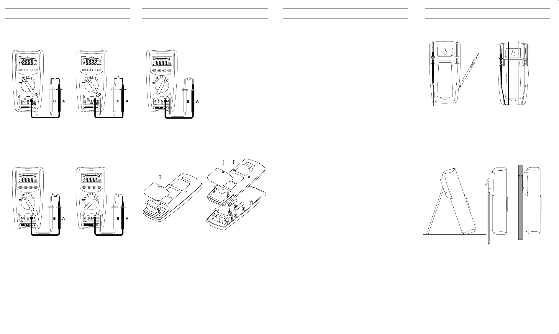
5.1.18 Das BENNING MM 6 wird durch einen Gummi-Schutzrahmen vor
mechanischer Beschädigung geschützt. Der Gummi-Schutzrahmen
ermöglicht es, das BENNING MM 6 während der Messungen aufzu-
stellen oder aufzuhängen.
6. Umgebungsbedingungen
- Das BENNING MM 6 ist für Messungen in trockener Umgebung vorgesehen,
- Barometrische Höhe bei Messungen: Maximal 2000 m,
- Überspannungskategorie/ Aufstellungskategorie: IEC 664/ IEC 1010-
1:1990 → 600 V Kategorie III; 1000 V Kategorie II,
- Verschmutzungsgrad: II,
- Schutzart: IP 30 (DIN VDE 0470-1 IEC/ EN 60529)
3 - erste Kennziffer: Schutz gegen Zugang zu gefährlichen Teilen und
Schutz gegen feste Fremdkörper, > 2,5 mm Durchmesser
0 - zweite Kennziffer: Kein Wasserschutz,
- Arbeitstemperatur und relative Luftfeuchte:
Bei Arbeitstemperatur von 0 °C bis 30 °C: relative Luftfeuchte kleiner 80 %,
Bei Arbeitstemperatur von 30 °C bis 40 °C: relative Luftfeuchte kleiner 75 %,
Bei Arbeitstemperatur von 40 °C bis 50 °C: relative Luftfeuchte kleiner 45 %,
- Lagerungstemperatur: Das BENNING MM 6 kann bei Temperaturen von
- 20 °C bis + 60 °C (Luftfeuchte 0 bis 80 %) gelagert werden. Dabei ist die
Batterie aus dem Gerät herauszunehmen.
7. Elektrische Angaben
Bemerkung: Die Messgenauigkeit wird angegeben als Summe aus
- einem relativen Anteil des Messwertes und
- einer Anzahl von Digit (d.h. Zahlenschritte der letzten Stelle).
Diese Messgenauigkeit gilt bei Temperaturen von 18 °C bis 28 °C und einer
relativen Luftfeuchtigkeit kleiner 80 %.

10/ 2004
BENNING MM 6
4
7.1 Gleichspannungsbereiche
Der Eingangswiderstand beträgt 10 MΩ (im 400 mV-Bereich 1GΩ).
Messbereich Auflösung Messgenauigkeit Überlastschutz
400 mV 100 µV ± (0,25 % des Messwertes + 5 Digit) 1000 VDC
4 V 1 mV ± (0,4 % des Messwertes + 1 Digit) 1000 VDC
40 V 10 mV ± (0,25 % des Messwertes + 1 Digit) 1000 VDC
400 V 100 mV ± (0,25 % des Messwertes + 1 Digit) 1000 VDC
1000 V 1 V ± (0,25 % des Messwertes + 1 Digit) 1000 VDC
7.2 Wechselspannungsbereiche
Der Eingangswiderstand beträgt 10 MΩ parallel 100 pF. Der Messwert wird
als echter Effektivwert (TRUE RMS) gewonnen und angezeigt. Bei nicht sinus-
förmigen Kurvenformen wird der Anzeigewert ungenauer. So ergibt sich für
folgende Crest-Faktoren ein zusätzlicher Fehler:
Crest-Factor von 1,4 bis 3,0 zusätzlicher Fehler + 1,5 %
Crest-Factor von 3,0 bis 4,0 zusätzlicher Fehler + 3,0 %
Messbereich Auflösung Messgenauigkeit
im Frequenzbereich 40 Hz - 1000 Hz Überlastschutz
400 mV 100 µV
± (2,0 % des Messwertes + 8 Digit)
im Frequenzbereich
50 Hz - 60 Hz für 400 mV-Bereich
750 Veff
4 V 1 mV ± (1,3 % des Messwertes + 5 Digit) *1*2 750 Veff
40 V 10 mV ± (1,3 % des Messwertes + 5 Digit) *2 750 Veff
400 V 100 mV ± (1,3 % des Messwertes + 5 Digit) *2 750 Veff
750 V 1 V ± (1,3 % des Messwertes + 5 Digit) *2 750 Veff
*1 ± (1,5 % + 5 Digit) im Frequenzbereich 500 Hz - 1 kHz
*2 ± (1,5 % + 5 Digit) für Messwerte > 50 % des Messbereichsendwetes
7.3 Gleichstrombereiche
Überlastungsschutz:
- 1 A (500 V)-Sicherung, flink am mA - Eingang,
- 10 A (500 V)-Sicherung, flink am 10 A - Eingang,
Messbereich Auflösung Messgenauigkeit Spannungsabfall
40 mA 10 µA ± (0,6 % des Messwertes + 2 Digit) 200 mV max.
400 mA 100 µA ± (0,7 % des Messwertes + 2 Digit) 2 V max.
10 A 10 mA ± (1,0 % des Messwertes + 3 Digit) 2 V max.
7.4 Wechselstrombereiche
Der Messwert wird als echter Effektivwert (TRUE RMS) gewonnen und
angezeigt. Bei nicht sinusförmigen Kurvenformen wird der Anzeigewert
ungenauer. So ergibt sich für folgende Crest-Faktoren ein zusätzlicher Fehler:
Crest-Factor von 1,4 bis 3,0 zusätzlicher Fehler + 1,5 %
Crest-Factor von 3,0 bis 4,0 zusätzlicher Fehler + 3,0 %
Überlastungsschutz:
- 1 A (500 V)-Sicherung, flink am mA - Eingang,
- 10 A (500 V)-Sicherung, flink am 10 A - Eingang,
Messbereich Auflösung Messgenauigkeit
im Frequenzbereich 40 Hz - 1000 Hz Spannungsabfall
40 mA 10 µA ± (2,0 % des Messwertes + 5 Digit) 200 mVeff max.
400 mA 100 µA ± (2,0 % des Messwertes + 5 Digit) 2 Veff max.
10 A 10 mA ± (2,5 % des Messwertes + 5 Digit) 2 Veff max.
7.5 Widerstandsbereiche
Überlastschutz bei Widerstandsmessungen: 600 Veff
Mess-
bereich
Auf-
lösung
Mess-
genauigkeit
Max.
Messstrom
Max. Leerlauf-
spannung

10/ 2004
BENNING MM 6
5
400 Ω 0,1 Ω ± (0,7 % des Messwertes + 3 Digit) 700 µA 1,3 V
4 kΩ 1 Ω ± (0,4 % des Messwertes + 3 Digit) 200 µA 1,3 V
40 kΩ 10 Ω ± (0,4 % des Messwertes + 3 Digit) 40 µA 1,3 V
400 kΩ 100 Ω ± (0,4 % des Messwertes + 3 Digit) 4 µA 1,3 V
4 MΩ 1 kΩ ± (0,6 % des Messwertes + 3 Digit) 400 nA 1,3 V
40 MΩ 10 kΩ ± (1,5 % des Messwertes + 5 Digit) 40 nA 1,3 V
7.6 Dioden- und Durchgangsprüfung
Die angegebene Messgenauigkeit gilt im Bereich zwischen 0,4 V und 0,8 V.
Überlastschutz bei Diodenprüfungen: 600 Veff
Der eingebaute Summer ertönt bei einem Widerstand R kleiner 30 Ω.
Mess-
bereich
Auf-
lösung
Mess-
genauigkeit
Max.
Messstrom
Max. Leerlauf-
spannung
1 mV ± (1,5 % des Messwertes + 5 Digit) 1,5 mA
3,0 V
7.7 Kapazitätsbereiche
Bedingungen: Kondensatoren entladen und entsprechend der angegebenen
Polarität angelegen.
Überlastschutz bei Kapazitätsmessungen: 600 Veff
Messbereich Auflösung Messgenauigkeit
4 nF 1 pF ± (3,0 % des Messwertes + 5 Digit)
40 nF 10 pF ± (2,0 % des Messwertes + 5 Digit)
400 nF 100 pF ± (2,0 % des Messwertes + 5 Digit)
4 µF 1 nF ± (2,0 % des Messwertes + 5 Digit)
40 µF 10 nF ± (2,0 % des Messwertes + 5 Digit)
400 µF 100 nF ± (2,0 % des Messwertes + 5 Digit)
4 mF 1 µF ± (2,0 % des Messwertes + 5 Digit)
40 mF 10 µF ± (5,0 % des Messwertes + 5 Digit)
7.8 Frequenzbereiche (bei Drehschalterbetätigung)
Überlastschutz bei Frequenzmessungen: 600 Veff
Mess-
bereich
Auf-
lösung Messgenauigkeit für 5 Veff max.
Min. Eingangs-
frequenz
Min. Empfind-
lichkeit
4 kHz 1 Hz
± (0,01 % des Messwertes + 1 Digit)
20 Hz 100 mVeff
40 kHz 10 Hz
± (0,01 % des Messwertes + 1 Digit)
200 Hz 100 mVeff
400 kHz
100 Hz
± (0,01 % des Messwertes + 1 Digit)
2 kHz 100 mVeff
4 MHz 1 kHz
± (0,01 % des Messwertes + 1 Digit)
20 kHz 250 mVeff
40 MHz 10 kHz
± (0,01 % des Messwertes + 1 Digit)
200 kHz 1 Veff
7.9 Frequenzanzeige bei Betätigung durch ~Hz-Taste
AC V Messbereich Messgenauigkeit Minimale Empfindlichkeit
400 mV ± (0,01 % des Messwertes + 5 Digit) 40 mVeff
4 V ± (0,01 % des Messwertes + 5 Digit) 0,2 Veff
40 V ± (0,01 % des Messwertes + 5 Digit) 2 Veff
400 V ± (0,01 % des Messwertes + 5 Digit) 20 Veff
750 V ± (0,01 % des Messwertes + 5 Digit) 200 Veff
AC V Messbereich Messgenauigkeit Minimale Empfindlichkeit
40 mA ± (0,01 % des Messwertes + 5 Digit) 8 mAeff
400 mA ± (0,01 % des Messwertes + 5 Digit) 80 mAeff

10/ 2004
BENNING MM 6
6
10 A ± (0,01 % des Messwertes + 5 Digit) 8 Aeff
8. Messen mit dem BENNING MM 6
8.1 Vorbereiten der Messung
Benutzen und lagern Sie das BENNING MM 6 nur bei den angegebenen
Lager- und Arbeitstemperaturbedingungen, vermeiden Sie dauernde Sonnen-
einstrahlung.
- Angaben von Nennspannung und Nennstrom auf den Sicherheitsmessleitung-
en überprüfen. Die zum Lieferumfang gehörenden Sicherheitsmessleitungen
entsprechen in Nennspannung und Nennstrom dem BENNING MM 6.
- Isolation der Sicherheitsmessleitungen überprüfen. Wenn die Isolation
beschädigt ist, sind die Sicherheitsmessleitungen sofort auszusondern.
- Sicherheitsmessleitungen auf Durchgang prüfen. Wenn der Leiter in der
Sicherheitsmessleitung unterbrochen ist, sind die Sicherheitsmessleitungen
sofort auszusondern.
- Bevor am Drehschalter eine andere Funktion gewählt wird, müssen die
Sicherheitsmessleitungen von der Messstelle getrennt werden.
- Starke Störquellen in der Nähe des BENNING MM 6 können zu instabiler
Anzeige und zu Messfehlern führen.
8.2 Spannungs- und Strommessung
Maximale Spannung gegen Erdpotential beachten!
Elektrische Gefahr!
Die höchste Spannung, die an den Buchsen
- COM-Buchse
- Buchse für V, Ω, Hz
- Buchse für mA-Bereich und der
- Buchse für 10 A-Bereich
des BENNING MM 6 gegenüber Erde liegen darf, beträgt 1000 V.
Elektrische Gefahr!
Maximale Schaltkreisspannung bei Strommessung 500 V! Bei
Sicherungsauslösung über 500 V ist eine Beschädigung des
Gerätes möglich. Von einem beschädigten Gerät kann eine
elektrische Gefährdung ausgehen!
8.2.1 Spannungsmessung
- Mit dem Drehschalter die gewünschte Funktion (V) am BENNING MM 6
wählen.
- Mit der Taste (blau) am BENNING MM 6 die zu messende Spannungsart
Gleich- (DC) oder Wechselspannung (AC) wählen.
- Die schwarze Sicherheitsmessleitung mit der COM-Buchse am
BENNING MM 6 kontaktieren.
- Die rote Sicherheitsmessleitung mit der Buchse für V, , Hz am
BENNING MM 6 kontaktieren.
- Die Sicherheitsmessleitungen mit den Messpunkten kontaktieren, Mess-
wert an der Digitalanzeige am BENNING MM 6 ablesen.
siehe Bild 2: Gleichspannungsmessung
siehe Bild 3: Wechselspannungsmessung
8.2.2 Strommessung
- Mit dem Drehschalter den gewünschten Bereich und die Funktion (mA
oder A) am BENNING MM 6 wählen.
- Mit der Taste (blau) am BENNING MM 6 die zu messende Stromart
Gleich- (DC) oder Wechselstrom (AC) wählen.
- Die schwarze Sicherheitsmessleitung mit der COM-Buchse am
BENNING MM 6 kontaktieren.
- Die rote Sicherheitsmessleitung mit der Buchse für mA-Bereich für
Ströme bis 400 mA bzw. mit der Buchse für 10 A-Bereich für Ströme von
größer 400 mA bis 10 A am BENNING MM 6 kontaktieren.
- Die Sicherheitsmessleitungen mit den Messpunkten kontaktieren, Mess-
wert an der Digitalanzeige am BENNING MM 6 ablesen.
siehe Bild 4: Gleichstrommessung
siehe Bild 5: Wechselstrommessung
8.3 Widerstandsmessung
- Mit dem Drehschalter die gewünschte Funktion (Ω) am BENNING MM 6

10/ 2004
BENNING MM 6
7
wählen.
- Die schwarze Sicherheitsmessleitung mit der COM-Buchse am
BENNING MM 6 kontaktieren.
- Die rote Sicherheitsmessleitung mit der Buchse für V, Ω, Hz am
BENNING MM 6 kontaktieren.
- Die Sicherheitsmessleitungen mit den Messpunkten kontaktieren, den
Messwert an der Digitalanzeige am BENNING MM 6 ablesen.
siehe Bild 6: Widerstandsmessung
8.4 Diodenprüfung
- Mit dem Drehschalter die gewünschte Funktion (Ω/ Summer- und
Dioden-Symbol) am BENNING MM 6 wählen.
- Mit der Taste (blau) am BENNING MM 6 die Umschaltung auf
Diodenprüfung vornehmen (Taste zweimal drücken).
- Die schwarze Sicherheitsmessleitung mit der COM-Buchse am
BENNING MM 6 kontaktieren.
- Die rote Sicherheitsmessleitung mit der Buchse für V, Ω, Hz am
BENNING MM 6 kontaktieren.
- Die Sicherheitsmessleitungen mit den Diodenanschlüssen kontaktieren,
den Messwert an der Digitalanzeige am BENNING MM 6 ablesen.
- Für eine normale in Flussrichtung angelegte Si-Diode wird die Flussspan-
nung zwischen 0,500 V bis 0,900 V angezeigt. Die Anzeige “000“ deutet
auf einen Kurzschluss in der Diode hin, die Anzeige “1” deutet auf eine
Unterbrechung in der Diode hin.
- Für eine in Sperrrichtung angelegte Diode wird “OL” angezeigt. Ist die
Diode fehlerhaft, werden “000” oder andere Werte angezeigt.
siehe Bild 7: Diodenprüfung
8.5 Durchgangsprüfung mit Summer
- Mit dem Drehschalter die gewünschte Funktion (Ω/ Summer- und Dioden-
Symbol) am BENNING MM 6 wählen.
- Mit der Taste (blau) am BENNING MM 6 die Umschaltung auf
Durchgangsprüfung vornehmen (Taste einmal drücken)
- Die schwarze Sicherheitsmessleitung mit der COM-Buchse am
BENNING MM 6 kontaktieren.
- Die rote Sicherheitsmessleitung mit der Buchse für V, Ω, Hz am
BENNING MM 6 kontaktieren.
- Die Sicherheitsmessleitungen mit den Messpunkten kontaktieren. Unterschreitet
der Leitungswiderstand zwischen der COM-Buchse und der Buchse für V, Ω,
Hz, F 30 Ω ertönt im BENNING MM 6 der eingebaute Summer.
siehe Bild 8: Durchgangsprüfung mit Summer
8.6 Kapazitätsmessung
Kondensatoren vor Kapazitätsmessungen vollständig entladen!
Niemals Spannung an die Buchsen für Kapazitätsmessung
anlegen! Das Gerät kann beschädigt oder zerstört werden! Von
einem beschädigten Gerät kann eine elektrische Gefährdung
ausgehen!
- Mit dem Drehschalter die gewünschte Funktion am BENNING MM 6
wählen.
- Polarität des Kondensators ermitteln und Kondensator vollständig
entladen.
- Die schwarze Sicherheitsmessleitung mit der COM-Buchse am
BENNING MM 6 kontaktieren.
- Die rote Sicherheitsmessleitung mit der Buchse für V, Ω, Hz am
BENNING MM 6 kontaktieren.
- Die Sicherheitsmessleitungen mit dem entladenen Kondensator entsprechend
seiner Polarität kontaktieren, Messwert an der Digitalanzeige am
BENNING MM 6 ablesen.
siehe Bild 9: Kapazitätsmessung
8.7 Frequenzmessung
- Mit dem Drehschalter die gewünschte Funktion (Hz) am BENNING MM 6
wählen.
- Die schwarze Sicherheitsmessleitung mit der COM-Buchse am
BENNING MM 6 kontaktieren.
- Die rote Sicherheitsmessleitung mit der Buchse für V, Ω, Hz am
BENNING MM 6 kontaktieren. Beachten Sie die minimale Empfindlichkeit
für Frequenzmessungen am BENNING MM 6!
- Die Sicherheitsmessleitungen mit den Messpunkten kontaktieren, den
Messwert an der Digitalanzeige am BENNING MM 6 ablesen.

10/ 2004
BENNING MM 6
8
siehe Bild 10: Frequenzmessung
9. Instandhaltung
Vor dem Öffnen das BENNING MM 6 unbedingt spannungsfrei
machen! Elektrische Gefahr!
Die Arbeit am geöffneten BENNING MM 6 unter Spannung ist ausschließlich
Elektrofachkräften vorbehalten, die dabei besondere Maßnahmen zur
Unfallverhütung treffen müssen.
So machen Sie das BENNING MM 6 spannungsfrei, bevor Sie das Gerät
öffnen:
- Entfernen Sie zuerst beide Sicherheitsmessleitungen vom Messobjekt.
- Entfernen Sie dann beide Sicherheitsmessleitungen vom BENNING MM 6.
- Schalten Sie den Drehschalter in die Schaltstellung “OFF”.
9.1 Sicherstellen des Gerätes
Unter bestimmten Voraussetzungen kann die Sicherheit im Umgang mit dem
BENNING MM 6 nicht mehr gewährleistet sein; zum Beispiel bei:
- Sichtbaren Schäden am Gehäuse,
- Fehlern bei Messungen,
- Erkennbaren Folgen von längerer Lagerung unter unzulässigen
Bedingungen und
- Erkennbaren Folgen von außerordentlicher Transportbeanspruchung.
In diesen Fällen ist das BENNING MM 6 sofort abzuschalten, von den Mess-
stellen zu entfernen und gegen erneute Nutzung zu sichern.
9.2 Reinigung
Reinigen Sie das Gehäuse äußerlich mit einem sauberen und trockenen Tuch
(Ausnahme spezielle Reinigungstücher). Verwenden Sie keine Lösungs- und/
oder Scheuermittel, um das Gerät zu reinigen. Achten Sie unbedingt darauf,
dass das Batteriefach und die Batteriekontakte nicht durch auslaufendes
Batterie-Elektrolyt verunreinigt werden.
Falls Elektrolytverunreinigungen oder weiße Ablagerungen im Bereich der
Batterie oder des Batteriegehäuses vorhanden sind, reinigen Sie auch diese
mit einem trockenen Tuch.
9.3 Batteriewechsel
Vor dem Öffnen das BENNING MM 6 unbedingt spannungsfrei
machen! Elektrische Gefahr!
Das BENNING MM 6 wird von einer 9-V-Blockbatterie gespeist. Ein
Batteriewechsel (siehe Bild 11) ist erforderlich, wenn in der Anzeige das
Batteriesymbol erscheint.
So wechseln Sie die Batterie:
- Entfernen Sie die Sicherheitsmessleitungen vom Messkreis.
- Entfernen Sie die Sicherheitsmessleitungen vom BENNING MM 6.
- Bringen Sie den Drehschalter in die Schaltstellung “OFF”.
- Entfernen Sie den Gummi-Schutzrahmen vom BENNING MM 6.
- Legen Sie das BENNING MM 6 auf die Frontseite und lösen Sie die Schlitz-
Schraube vom Batteriedeckel.
- Heben Sie den Batteriedeckel (im Bereich der Gehäusevertiefungen) vom
Unterteil ab.
- Heben Sie die entladene Batterie aus dem Batteriefach, und nehmen Sie
die Batteriezuleitungen vorsichtig von der Batterie ab.
- Die neue Batterie ist mit den Batteriezuleitungen zu verbinden, und ordnen
Sie diese so, dass sie nicht zwischen den Gehäuseteilen gequetscht
werden. Legen Sie dann die Batterie an die dafür vorgesehene Stelle im
Batteriefach.
- Rasten Sie den Batteriedeckel an das Unterteil an, und ziehen Sie die
Schraube an.
- Setzen Sie das BENNING MM 6 in den Gummi-Schutzrahmen ein.
siehe Bild 11: Batteriewechsel

10/ 2004
BENNING MM 6
9
Leisten Sie Ihren Beitrag zum Umweltschutz! Batterien dürfen
nicht in den Hausmüll. Sie können bei einer Sammelstelle für
Altbatterien bzw. Sondermüll abgegeben werden. Informieren
Sie sich bitte bei Ihrer Kommune.
9.4 Sicherungswechsel
Vor dem Öffnen das BENNING MM 6 unbedingt spannungsfrei
machen! Elektrische Gefahr!
Das BENNING MM 6 wird durch eine eingebaute Sicherung (G-Schmelzeinsatz)
1 A flink und eine eingebaute Sicherung (G-Schmelzeinsatz) 10 A flink vor Über-
lastung geschützt (siehe Bild 12)
So wechseln Sie die Sicherungen:
- Entfernen Sie die Sicherheitsmessleitungen vom Messkreis.
- Entfernen Sie die Sicherheitsmessleitungen vom BENNING MM 6.
- Bringen Sie den Drehschalter in die Schaltstellung “OFF”.
- Entfernen Sie den Gummi-Schutzrahmen vom BENNING MM 6.
- Legen Sie das BENNING MM 6 auf die Frontseite und lösen Sie die Schlitz-
Schraube vom Batteriedeckel.
- Heben Sie den Batteriedeckel (im Bereich der Gehäusevertiefungen) vom
Unterteil ab.
Lösen Sie keine Schrauben an der gedruckten Schaltung des
BENNING MM 6!
- Entfernen Sie die beiden äußeren Schrauben (schwarz) und die zwei
Schrauben neben der gedruckten Schaltung aus dem Unterteil (Gehäuse-
boden).
- Heben Sie den Gehäuseboden im unteren Bereich an und nehmen Sie ihn
im oberen Bereich vom Frontteil ab.
- Heben Sie ein Ende der defekten Sicherung aus dem Sicherungshalter.
- Schieben Sie die defekte Sicherung vollständig aus dem Sicherungshalter.
- Setzen Sie die neue Sicherung mit gleichem Nennstrom, gleicher Auslöse-
charakteristik und gleichen Abmessungen ein.
- Ordnen Sie die neue Sicherung mittig in dem Halter an.
- Ordnen Sie die Batteriezuleitungen so, dass sie nicht zwischen den
Gehäuseteilen gequetscht werden.
- Rasten Sie den Gehäuseboden an das Frontteil an und montieren Sie die
vier Schrauben.
- Rasten Sie den Batteriedeckel an das Unterteil an, und ziehen Sie die
Schraube an.
- Setzen Sie das BENNING MM 6 in den Gummi-Schutzrahmen ein.
siehe Bild 12: Sicherungswechsel
9.5 Kalibrierung
Um die angegebenen Genauigkeiten der Messergebnisse zu erhalten, muss
das Gerät regelmäßig durch unseren Werksservice kalibriert werden. Wir
empfehlen ein Kalibrierintervall von einem Jahr.
10. Anwendung des Gummi-Schutzrahmens
- Sie können die Sicherheitsmessleitungen verwahren, indem Sie die
Sicherheitsmessleitungen um den Gummi-Schutzrahmen wickeln und
die Spitzen der Sicherheitsmessleitungen geschützt an den Gummi-Schutz-
rahmen anrasten (siehe Bild 13).
- Sie können eine Sicherheitsmessleitung so an den Gummi-Schutzrahmen
anrasten, dass die Messspitze freisteht, um die Messspitze gemeinsam
mit dem BENNING MM 6 an einen Messpunkt zu führen.
- Die rückwärtige Stütze am Gummi-Schutzrahmen ermöglicht, das
BENNING MM 6 schräg aufzustellen (erleichtert die Ablesung) oder
aufzuhängen (siehe Bild 14).
- Der Gummi-Schutzrahmen besitzt eine Öse, die für eine Aufhängemög-
lichkeit genutzt werden kann.
siehe Bild 13: Aufwicklung der Sicherheitsmessleitung
siehe Bild 14: Aufstellung des BENNING MM 6

10/ 2004
BENNING MM 6
10
Operating Manual
BENNING MM 6
Digital Multimeter for
- DC voltage measurement
- AC voltage measurement
- DC current measurement
- AC current measurement
- Resistance measurement
- Diode testing
- Continuity testing
- Capacity measurement
- Frequency measurement
Contents
1. Operating instructions
2. Safety notes
3. Contents of delivery
4. Description of unit
5. General data
6. Ambient conditions
7. Electrical data
8. Measuring with the BENNING MM 6
9. Maintenance
10. How to use the protective rubber holster
1. Operating instructions
This operating manual is intended for:
- electricians and
- qualified electrotechnical persons.
The BENNING MM 6 is designed for measurements in dry surroundings.It must
not be used in electrical circuits with rated voltages higher than 1000 V DC and
750 V AC (for more details, see section 6 “Ambient conditions”).
The following symbols are used in the Operating Manual and on the
BENNING MM 6 itself:
This symbol indicates an electrical hazard.
This symbol indicates sources of danger when using the
BENNING MM 6 (see documentation).
This symbol on the BENNING MM 6 indicates that the unit is
protection insulated (safety class II).
This symbol on the BENNING MM 6 indicates the fuses which it
contains.
This symbol appears in the display for a discharged battery.
This symbol indicates the “diode-testing” application.
This symbol indicates the “continuity testing” application. The buzzer
provides an audible signal.
This symbol marks the range “capacity testing”.
(DC)-voltage or current.
(AC)-voltage or current.
Earth (voltage to earth).

10/ 2004
BENNING MM 6
11
2. Safety notes
Example safety note:
Electrical hazard!
Comply with the safety instructions!
Before using the BENNING MM 6, read the operating instructions carefully.
Always comply with the safety notes given in the operating instructions. This is
essential in order to avoid accidents and damage to the BENNING MM 6.
3. Contents of delivery
The following items make up the standard BENNING MM 6 package:
3.1 one BENNING MM 6,
3.2 one safety test lead, red (L = 1,4 m; tip Ø = 4 mm),
3.3 one safety test lead, black (L = 1,4 m; tip Ø = 4 mm),
3.4 one protective rubber holster,
3.5 one compact protection carrying case,
3.6 one 9-V block battery and two different fuses (integrated in the new unit
when it is supplied),
3.7 one set Operating Manual.
Note on replaceable parts:
- The BENNING MM 6 contains fuses for overload protection:
One fuse rated 10 A rapid-acting (500 V), D = 6.35 mm, L = 32 mm and one
fuse rated 1 A rapid-acting (500 V), D = 6.35 mm, L = 32 mm.
- The BENNING MM 6 is supplied by one 9-V block battery (IEC 6 LR 61).
- The above mentioned safety cable ATL 2 (tested spare part) are approved
in accordance with CAT III 1000 V and for a current up 10 A.
4. Description of unit
See fig. 1 Front panel
The display and operating elements shown in fig. 1 are as follows:
Digital display, for the measurement reading, bar graph and display for
overrange indication,
Polarity display,
Battery display, appears when battery discharged,
RANGE button, switchover between automatic and manual measuring
rang e,
HOLD button,
~Hz button, in ACV and ACA range, switchover in frequency display,
Button (blue), for DC voltage and current and AC voltage and current,
resistance measurement and/or diode testing, frequency measurement
and/or speed measurement (r.p.m),
Rotating switch, for selecting measurement function,
Socket (positive1) for V, Ω, Hz,
COM socket, joint socket for measurement of current, voltage, resistance,
frequency, capacity, continuity and diode testing,
Socket (positive), for mA range, for currents up to 400 mA,
Socket (positive), for 10-A range, for currents up to 10 A,
Protective rubber holster
1) The automatic polarity display for DC current and voltage refers to this.
5. General data
5.1 General data on multimeter
5.1.1 The digital display is designed as a 4 digit liquid-crystal indicator with
14 mm digit height and decimal point. The highest value displayed is
4000.
5.1.2 The bar graph display consists of 82 segments.
5.1.3 The polarity indication functions automatically. Only a polarity
contrary to the socket definition is indicated, as “-”.
5.1.4 The range overload will be displayed with "OL" or "-OL" and sometimes
with an acoustic signal.
Attention: no display or warning by complete overload.
5.1.5 The “RANGE” button is for switching the manual measurement
ranges further on while showing “RANGE” simultaneously in the
display. When the button is pressed for longer (2 sec.), automatic range
selection is selected (“RANGE” disappears from display).
5.1.6 “HOLD” - storage of measurement reading. When the “HOLD” button
is pressed, the measurement reading is stored in the memory.
The symbol “HOLD” appears in the display at the same time. When

10/ 2004
BENNING MM 6
12
the button is pressed a second time, the unit switches back to
measurement mode.
5.1.7 The button “HZ” changes the display to frequency in the AC
voltage and current range. When the button is pressed a second time,
the unit switches back to the previous mode.
5.1.8 When the rotating switch is at V, mA and A, the blue button
switches between DC and AC operation. In position Ω, it switches
from resistance measurement to continuity test and when pressed
another time, to diode test. In switch position Hz, it switches from
frequency measurement to RPM mode. The RPM mode is equivalent
to a mathematical conversion from Hz (cycles per second) to RPM
(rotations/cycles per minute). 1 Hz is equivalent to 60 r.p.m. (rotations/
cycles per minute).
5.1.9 The nominal measurement rate of the BENNING MM 6 is 2
measurements per sec. for the digital display and 12 measurements
for the bar graph display.
5.1.10 The BENNING MM 6 is switched on and off by the rotating switch .
Switch-off position “OFF”.
5.1.11 The BENNING MM 6 switches off automatically after approx. 30
minutes (APO = Auto-Power Off). It switches back on again when the
HOLD button or another button is pressed. A buzzer signal is given 15
sec. before it switches off automatically.
5.1.12 Temperature coefficient of measurement value: 0.15 x (stated
measurement accuracy)/ °C < 18 °C or > 28 °C relative to the value at
the reference temperature of 23 °C.
5.1.13 The BENNING MM 6 is powered by one 9-V block battery (IEC 6 LR
61).
5.1.14 When the battery voltage drops beneath the specified operating voltage
of the BENNING MM 6, the low battery symbol appears in the display.
5.1.15 The life span of a battery is approx. 300 hours (alkali battery).
5.1.16 Dimensions:
(L x W x H) = 180 x 88 x 33,5 mm without protective rubber holster
(L x W x H) = 188 x 94 x 40 mm with protective rubber holster
Weight:
300 g without protective rubber holster
440 g with protective rubber holster
5.1.17 The safety test leads are 4 mm plug-type leads. The safety test
leads are expressly suitable for the rated voltage and power of the
BENNING MM 6.
5.1.18 The BENNING MM 6 is protected against mechanical damage by a
protective rubber holster . The protective rubber holster makes it
possible to suspend the BENNING MM 6 during the measuring process
or to stand it upright.
6. Ambient conditions
- The BENNING MM 6 is designed only for measuring in dry surroundings.
- Maximum barometric height during measurement: 2000 m.
- Overvoltage category / set-up category: IEC 664/ IEC 1010-1:1990 → 600
V category III;
1000 V category II.
- Degree of contamination: II.
- Protection Class: IP 30 (DIN VDE 0470-1 IEC/ EN 60529)
IP 30 means: Protection against access to dangerous parts and protection
against solid impurities of a diameter > 2.5 mm, (3 - first index). No
protection against water, (0 - second index).
- Operating temperature and relative humidity:
At operating temperature of 0 °C to 30 °C: relative humidity under 80 %,
At operating temperature of 30 °C to 40 °C: relative humidity under 75 %,
- At operating temperature of 40 °C to 50 °C: relative humidity under 45 %.
- Storage temperature: The BENNING MM 6 can be stored at temperatures
from - 20 °C to + 60 °C (humidity 0 up to 80 %). The batteries must be
removed from the unit.
7. Electrical data
Note: The measurement accuracy is stated as the sum of
- a relative proportion of the measurement value and
- a number of digits (i.e. numerical steps of the last place).
This measurement accuracy applies for a temperature of 18 °C to 28 °C and a
maximum relative humidity of max. 80 %.
7.1 DC voltage range
The input resistance is 10 MΩ (in 400 mV-range 1GΩ).

10/ 2004
BENNING MM 6
13
Measuring range Resolution Measurement accuracy Overload protection
400 mV 100 µV ± (0.25 % of reading + 5 digits) 1000 VDC
4 V 1 mV ± (0.4 % of reading + 1 digits) 1000 VDC
40 V 10 mV ± (0.25 % of reading + 1 digits) 1000 VDC
400 V 100 mV ± (0.25 % of reading + 1 digits) 1000 VDC
1000 V 1 V ± (0.25 % of reading + 1 digits) 1000 VDC
7.2 AC voltage ranges
The input resistance is 10 MΩ parallel 100 pF. The measurement value is
obtained as a true RMS value and displayed as such. With non-sinusoidal
curves, the value displayed is less accurate. This results in an additional error
for the following crest factors:
Crest factor of 1.4 to 3.0, additional error + 1.5 %.
Crest factor of 3.0 to 4.0, additional error + 3.0 %.
Measuring range Resolution Measurement accuracy in frequency range
40 Hz - 1000 Hz Overload protection
400 mV 100 µV
± (2.0 % of reading + 8 digits) in frequency
range 50 Hz - 60 Hz for 400 mV-range
750 Veff
4 V 1 mV ± (1.3 % of reading + 5 digits) *1*2 750 Veff
40 V 10 mV ± (1.3 % of reading + 5 digits) *2 750 Veff
400 V 100 mV ± (1.3 % of reading + 5 digits) *2 750 Veff
750 V 1 V ± (1.3 % of reading + 5 digits) *2 750 Veff
*1 ± (1.5 % + 5 Digit) in frequency range 500 Hz - 1 kHz
*2 ± (1.5 % + 5 Digit) for measuring ranges > 50 % of the measuring range value
7.3 DC ranges
Overload protection
- 1 A (500 V) fuse, rapid on mA input
- 10 A (500 V) fuse, rapid on 10 A input
Measuring range Resolution Measurement accuracy
Voltage drop
40 mA 10 µA ± (0.6 % of reading + 2 digits) 200 mV max.
400 mA 100 µA ± (0.7 % of reading + 2 digits) 2 V max.
10 A 10 mA ± (1.0 % of reading + 3 digits) 2 V max.
7.4 AC ranges
The measurement reading is obtained as a true RMS reading and displayed
as such. With non-sinusoidal curves, the value displayed is less accurate. This
results in an additional error for the following crest factors:
Crest factor of 1.4 to 3.0, additional error + 1.5 %.
Crest factor of 3.0 to 4.0, additional error + 3.0 %.
Overload protection:
- 1 A (500 V) fuse, rapid on mA input
- 10 A (500 V) fuse, rapid on 10 A input
Measuring range Resolution Measurement accuracy in frequency range
40 Hz - 1000 Hz
Voltage drop
40 mA 10 µA ± (2.0 % of reading + 5 digits) 200 mVeff max.
400 mA 100 µA ± (2.0 % of reading + 5 digits) 2 Veff max.
10 A 10 mA ± (2.5 % of reading + 5 digits) 2 Veff max.
7.5 Resistance ranges
Overload protection for resistance measurements: 600 Veff
Measuring
range Resolution Measurement accuracy Max. meas.
current
Max. no-load
voltage
400 Ω 0,1 Ω ± (0.7 % of reading + 3 digits) 700 µA 1,3 V

10/ 2004
BENNING MM 6
14
4 kΩ 1 Ω ± (0.4 % of reading + 3 digits) 200 µA 1,3 V
40 kΩ 10 Ω ± (0.4 % of reading + 3 digits) 40 µA 1,3 V
400 kΩ 100 Ω ± (0.4 % of reading + 3 digits) 4 µA 1,3 V
4 MΩ 1 kΩ ± (0.6 % of reading + 3 digits) 400 nA 1,3 V
40 MΩ 10 kΩ ± (1.5 % of reading + 5 digits) 40 nA 1,3 V
7.6 Diode and continuity testing
The stated measurement accuracy applies in the range between 0.4 and
0.8 V.
Overload protection for diode testing: 600 Veff
The integrated buzzer sounds at resistances R < 30 Ω.
Measuring
range Resolution Measurement accuracy Max. meas.
current
Max. no-load
voltage
1 mV ± (1.5 % of reading + 5 digits) 1,5 mA
3,0 V
7.7 Capacity ranges
Conditions: capacitors discharged and connected in accordance with the
polarity stated.
Overload protection for capacity measurements: 600 Veff
Measuring range Resolution Measurement accuracy
4 nF 1 pF ± (3,0 % of reading + 5 digits)
40 nF 10 pF ± (2,0 % of reading + 5 digits)
400 nF 100 pF ± (2,0 % of reading + 5 digits)
4 µF 1 nF ± (2,0 % of reading + 5 digits)
40 µF 10 nF ± (2,0 % of reading + 5 digits)
400 µF 100 nF ± (2,0 % of reading + 5 digits)
4 mF 1 µF ± (2,0 % of reading + 5 digits)
40 mF 10 µF ± (5,0 % of reading + 5 digits)
7.8 Frequency range (set with rotating switch)
Overload protection for frequency measurements: 600 Veff
Measuring
Range Resolution Measurement accuracy
for
5 Veff max.
Min.
input
frequency
Min.
Sensitivity
4 kHz 1 Hz ± (0.01 % of reading + 1 digit) 20 Hz 100 mVeff
40 kHz 10 Hz ± (0.01 % of reading + 1 digit) 200 Hz 100 mVeff
400 kHz
100 Hz ± (0.01 % of reading + 1 digit) 2 kHz 100 mVeff
4 MHz 1 kHz ± (0.01 % of reading + 1 digit) 20 kHz 250 mVeff
40 MHz 10 kHz ± (0.01 % of reading + 1 digit) 200 kHz 1 Veff
7.9 Frequency display (when ~Hz button pressed)
AC V Measuring Range
Measurement accuracy Minimum Sensitivity
400 mV ± (0.01 % of reading + 5 digits) 40 mVeff
4 V ± (0.01 % of reading + 5 digits) 0,2 Veff
40 V ± (0.01 % of reading + 5 digits) 2 Veff
400 V ± (0.01 % of reading + 5 digits) 20 Veff
750 V ± (0.01 % of reading + 5 digits) 200 Veff
AC V Measuring Range
Measurement accuracy Minimum Sensitivity
40 mA ± (0.01 % of reading + 5 digits) 8 mAeff
400 mA ± (0.01 % of reading + 5 digits) 80 mAeff
10 A ± (0.01 % of reading + 5 digits) 8 Aeff

10/ 2004
BENNING MM 6
15
8. Measuring with the BENNING MM 6
8.1 Preparation for measurement
Store and use the BENNING MM 6 only under the correct temperature
conditions stated. Always avoid longer exposure to sunlight.
- Check the rated voltage and rated current stated on the safety test leads.
The safety test leads supplied with the unit are suitable for the rated voltage
and current of the BENNING MM 6.
- Check the insulation of the safety test leads. If the insulation is damaged in
any way, do not use the leads.
- Check the continuity of the safety test leads. If the conductor in the safety
test lead is interrupted, do not use the leads.
- Before selecting another function with the rotating switch , always
disconnect the safety test leads from the measuring point.
- Sources of strong current in the vicinity of the BENNING MM 6 may cause
unstable or incorrect readings.
8.2 Voltage and current measurement
Always observe the maximum voltage to earth potential! Electrical hazard!
The maximum voltage which may be applied to the sockets
- COM- socket
- socket for V, Ω, Hz
- socket for mA range and the
- socket for 10 A range
of the BENNING MM 6 to earth is 1000 V.
Electrical hazard!
Maximum switching-circuit voltage for current measurement,
500 V! If the fuse triggers over 500 V, the unit may be damaged.
A damaged unit may represent an electrical hazard!
8.2.1 Voltage measurement
- With the rotating switch , select the desired function (V) on the
BENNING MM 6.
- With the blue button on the Benning MM 6, select the type of voltage to
be measured (DC or AC voltage)
- Connect the black safety test lead to the COM socket on the
BENNING MM 6.
- Connect the red safety test lead to the socket for V, Ω, Hz on the
BENNING MM 6.
- Connect the safety test leads to the measuring points. Read the measurement
value displayed in the digital display of the BENNING MM 6.
See fig. 2: DC-voltage measurement
See fig. 3: AC-voltage measurement
8.2.2 Current measurement
- With the rotating switch , select the desired range and function (mA or A)
on the BENNING MM 6.
- With the blue button on the Benning MM 6, select the type of current to
be measured (DC or AC current).
- Connect the black safety test lead to the COM socket on the
BENNING MM 6.
- Connect the red safety test lead to the socket for mA range, for current
up to 400 mA or to the socket for the 10 A range, for currents greater than
400 mA up to 10 A on the BENNING MM 6.
- Connect the safety test leads to the measuring points. Read the measurement
value displayed in the digital display of the BENNING MM 6.
See fig. 4: DC-current measurement
See fig. 5: AC-current measurement
8.3 Resistance measurement
- With the rotating switch , select the desired function (Ω) on the
BENNING MM 6.
- Connect the black safety test lead to the COM socket on the
BENNING MM 6.
- Connect the red safety test lead to the socket for V, Ω, Hz on the
BENNING MM 6.
- Connect the safety test leads to the measuring points. Read the measurement
value displayed in the digital display of the BENNING MM 6.
See fig. 6: Resistance measurement
8.4 Diode testing
- With the rotating switch , select the desired function (Ω/ buzzer and diode

10/ 2004
BENNING MM 6
16
symbol) on the BENNING MM 6.
- Using the blue button on the BENNING MM 6, switch to diode testing
(press button twice)
- Connect the black safety test lead to the COM socket on the
BENNING MM 6.
- Connect the red safety test lead to the socket for V, Ω, Hz on the
BENNING MM 6.
- Contact the diode connections with the safety test leads and read
the measurement value displayed in the digital display of the
BENNING MM 6.
- For a normal silicone diode located in flow direction, the flow voltage
between 0.500 V and 0.900 V is displayed. If “000” appears in the display,
there may be a short circuit in the diode. If “1” appears in the display, there
may be an interruption in the diode.
- For a diode located in the non-conducting direction “OL” appears. If the
diode is defective, “000” or other figures appear.
See fig. 7: Diode testing
8.5 Continuity testing with buzzer
- With the rotating switch , select the desired function (Ω/ buzzer and diode
symbol) on the BENNING MM 6.
- Using the blue button on the BENNING MM 6, switch to continuity test
(press button once)
- Connect the black safety test lead to the COM socket on the
BENNING MM 6.
- Connect the red safety test lead to the socket for V, Ω, Hz on the
BENNING MM 6.
- Contact the measuring points with the safety test leads. If the test lead
resistance between the COM socket and the socket for V, Ω, Hz on
the BENNING MM 6 is lower than 30 Ω the built-in buzzer is activated.
See fig. 8: Continuity testing with buzzer
8.6 Capacitance measurement
Discharge capacitors fully before measurement! Never apply
voltage to the sockets for capacitance measurement as this
may cause irreparable damage to the unit. A damaged unit may
represent an electrical hazard!
- With the rotating switch , select the desired function on the
BENNING MM 6.
- Determine the polarity of the capacitor and discharge it completely.
- Connect the black safety test lead to the COM socket on the
BENNING MM 6.
- Connect the red safety test lead to the socket for V, Ω, Hz on the
BENNING MM 6.
- Contact the discharged capacitor with the safety test leads observing
correct polarity. Read the measurement value on the digital display of
the BENNING MM 6.
See fig. 9: Capacity measurement
8.7 Frequency measurement
- With the rotating switch , select the desired function (Hz) on the
BENNING MM 6.
- Connect the black safety test lead to the COM socket on the
BENNING MM 6.
- Connect the red safety test lead to the socket for V, Ω, Hz on
the BENNING MM 6. Remember the minimum sensitivity for frequency
measurements using the BENNING MM 6!
- Contact the measuring points with the safety test leads and read the
measurement result on the digital display on the BENNING MM 6.
See fig. 10: Frequency measurement
9. Maintenance
Before opening the BENNING MM 6, ensure that it is not
connected to a source of voltage! Electrical hazard!
Any work required on the BENNING MM 6 when it is under voltage must be

10/ 2004
BENNING MM 6
17
done only by a qualified electrician. Special steps must be taken to prevent
accidents.
Before opening the BENNING MM 6, remove it from all sources of voltage as
follows:
- First remove both safety test leads from the measurement points.
- Remove both safety test leads from the BENNING MM 6
- Turn the rotating switch to “OFF”.
9.1 Securing the unit
Under certain circumstances, the safety of the BENNING MM 6 can no longer
be guaranteed. This may be the case if:
- there are visible signs of damage on the unit,
- errors occur in measurements,
- the unit has been stored for a long period of time under the wrong
conditions, and
- if the unit has been subjected to rough handling during transport.
In these cases, the BENNING MM 6 must be switched off immediately, removed
from the measuring points and secured to prevent it from being used again.
9.2 Cleaning
Clean the outside of the unit with a clean dry cloth. (Exception: any type of
special cleaning cloth). Never use solvents or abrasives to clean the testing unit.
Ensure that the battery compartment and the battery contacts have not been
contaminated by electrolyte leakage.
If any electrolyte or white deposits are seen near to the battery or in the battery
compartment, remove them with a dry cloth, too.
9.3 Battery replacement
Before opening the BENNING MM 6, ensure that it is not
connected to a source of voltage! Electrical hazard!
The BENNING MM 6 is powered by 9-V block battery. The battery must be
replaced (see fig. 11) when the battery symbol appears in the display .
To replace the battery, proceed as follows:
- First remove the safety test leads from the measurement circuit.
- Remove the safety test leads from the BENNING MM 6.
- Turn the rotating switch to “OFF”.
- Remove the protective rubber holster from the BENNING MM 6.
- Lay the BENNING MM 6 on its front and loosen the screw from the cover of
the battery compartment.
- Lift the battery compartment cover (at the recesses in the housing) off the
bottom part.
- Lift the discharged battery out of the battery compartment and remove the
battery leads carefully from the battery.
- Connect the new battery with the battery leads and arrange them in such a
way that they are not crushed between the two halves of the housing. Then
place the battery in the correct position in the battery compartment.
- Clip the battery cover onto the bottom part and tighten the screw.
- Replace the BENNING MM 6 in its protective rubber holster .
See fig. 11: Battery replacement
Remember the environment! Do not dispose of used batteries
with domestic waste. Dispose of them at a battery-collection
point or as toxic waste. Your local authority will give you the
information you need.
9.4 Fuse replacement
Before opening the BENNING MM 6, ensure that it is not
connected to a source of voltage! Electrical hazard!
The BENNING MM 6 is protected from overloading by two integrated melt
fusees (1 A rapid acting and 10 A rapid acting) (see fig. 12)
To replace the fuses, proceed as follows:
- Disconnect the safety test leads from the measurement circuit.

10/ 2004
BENNING MM 6
18
- Disconnect the safety test leads from the BENNING MM 6.
- Turn the rotating switch to the “OFF” position.
- Remove the protective rubber holster from the BENNING MM 6.
- Lay the BENNING MM 6 on its front and loosen the screw from the cover of
the battery compartment.
- Lift the battery-compartment cover (at recesses in housing) off the bottom
part.
Do not loosen any of the screws on the printed circuit of the
BENNING MM 6.
- Remove the two outer screws (black) and the two screws beside the printed
circuit from the base of the housing.
- Lift the housing base at the bottom and remove it from the top of the front
part.
- Lift one end of the defective fuse out of the fuse holder.
- Push the defective fuse out of the fuse holder completely.
- Replace the defective fuse with another of the same rated power, same
triggering characteristics and same dimensions.
- Push the new fuse into the centre of the holder.
- Arrange the battery leads in such a way that they are not crushed between
the housing parts.
- Clip the housing base into the front part and replace the four screws.
- Clip the battery cover onto the bottom part and tighten the screw.
- Replace the BENNING MM 6 in its protective rubber holster .
See fig. 12: Fuse replacement
9.5 Calibration
To achieve the desired degree of accuracy in your measurement readings, the
unit must be calibrated regularly by our field service. We recommend calibrating
your testing unit once per year.
10. How to use the protective rubber holster
- The safety test leads can be stored by coiling them round the protective
rubber holster and clipping the probe into the holster so that they are
sufficiently protected (see fig. 13)
- You can clip one lead onto the protective rubber holster in such a way
that the measuring probe projects. This allows you to bring the measuring
probe and the BENNING MM 6 up to the measuring point together.
- The support at the back of the holster can be used to prop the
BENNING MM 6 up in a diagonal position (to make reading easier) or to
suspend it (see fig. 14).
- The protective rubber holster has an eyelet for suspending the unit in a
convenient position.
See fig. 13: Wrapping up the safety test leads
See fig. 14: Standing up the BENNING MM 6
Table of contents
Languages:
Other PEWA Multimeter manuals