XFtp XPro User manual

XPro
Digital Multimeter
Operation Manual


XPro - Operation Manual
1
Table of Contents
Overview ........................................................................ 3
Unpacking Inspection .................................................. 4
Safety Information ........................................................ 5
Rules for Safe Operation ............................................. 6
International Electrical Symbols ................................ 8
The Meter Structure ...................................................... 9
Rotary Switch .............................................................. 10
Functional Buttons .................................................... 11
Display Symbols ......................................................... 12
Measurement Operation ............................................. 14
DC and AC Voltage Measurement ........................... 14
DC and AC Current Measurement ........................... 16
Resistance Measurement ......................................... 18
Diode Measurement ................................................. 20
Continuity Testing ..................................................... 22
Capacitance Measurement ....................................... 24
Temperature Measurement ....................................... 26
Transistor Measurement ........................................... 27
Frequency Measurement ......................................... 28
Sleep Mode ............................................................... 29
Operation of Hold Mode ........................................... 29
General Specifications ............................................... 30
Accuracy Specifications ............................................. 32
DC Voltage ............................................................... 32
AC Voltage ............................................................... 32
DC Current ............................................................... 33
AC Current ............................................................... 33
Resistance ............................................................... 34
Diodes Test ............................................................... 34
Continuity Test ......................................................... 34
Capacitance ............................................................. 35
Temperature .............................................................. 35
Transistor Test .......................................................... 36
Frequency ................................................................ 36

XPro - Operation Manual
2
Maintenance ................................................................ 37
General Service ........................................................ 37
Replacing the Fuse .................................................. 38
Replacing the Battery .............................................. 39
Warranty Information ................................................. 40

XPro - Operation Manual
3
The XFTP XPro Digital Multimeter (hereafter referred to
as “the Meter”) is a hand-held measuring instrument that
includes a large LCD.
The Meter can measure AC/DC Voltage, AC/DC Current,
Resistance, Capacitance, Temperature, Frequency,
Transistor, Diode and Continuity. It also includes Data
Hold, Full Icon Display, Overload Protection and Sleep
Mode features.
Overview
!
WARNING: To avoid electric shock or personal
injury, read the Safety Information and Rules
for Safe Operation sections carefully before
using the Meter.

XPro - Operation Manual
4
Unpacking Inspection
Open the package and remove the Meter. Check the
following items carefully to see if there are any missing
or damaged parts:
• Operation Manual
• Test Leads
• Multipurpose Socket
• Temperature Probe
• 9 Volt Battery
In the event that you find any missing or damaged
parts, please contact Trilithic for a replacement.

XPro - Operation Manual
5
Safety Information
This Meter complies with the standards IEC61010: in
pollution degree 2, overvoltage category (CAT. II 1000V,
CAT. III 600V) and double insulation.
CAT. II: Local level, appliance, PORTABLE EQUIPMENT
etc., with smaller transient voltage overvoltages than
CAT. III
CAT. III: Distribution level, fixed installation, with smaller
transient overvoltages than CAT. IV
Use the Meter only as specified in this operating manual,
otherwise the protection provided by the Meter may be
impaired.
In this manual, a Warning identifies conditions and
actions that pose hazards to the user, or may damage
the Meter or the equipment under test.
A Note identifies the information that user should pay
close attention to.
International electrical symbols used on the Meter and in
this Operation Manual are explained on Page 8.

XPro - Operation Manual
6
Rules for Safe Operation
• Inspect the case before using the Meter. Do not
use the Meter if it is damaged or the case (or part
of the case) is removed. Look for cracks or
missing plastic and pay attention to the insulation
around the connectors.
• Inspect the test leads for damaged insulation or
exposed metal. Check the test leads for
continuity. Replace damaged test leads with
identical model number or electrical specifications
before using the Meter.
• Do not apply more than the rated voltage, as
marked on the Meter, between the terminals or
between any terminal and grounding.
• The Meter is suitable for indoor use.
• The rotary switch should be placed in the right
position and no change of range should be made
during a measurement to prevent damage to the
Meter.
• When the Meter is working at an effective voltage
over 60V in DC or 30V rms in AC, special care
should be taken for danger of electric shock.
• Use the proper terminals, function, and range for
your measurements.
!
WARNING: To avoid possible electric shock or
personal injury, and to avoid possible damage to
the Meter or the equipment under test, adhere to
the following rules:

XPro - Operation Manual
7
• If the value to be measured is unknown, use the
maximum measurement position and reduce the
range step by step until a satisfactory reading is
obtained.
• Do not use or store the Meter in an environment of
high temperature, humidity, explosive, flammable
or strong magnetic field.
• The performance of the Meter may deteriorate with
exposure to high humidity.
• When using the test leads, keep your fingers
behind the finger guards.
• Disconnect circuit power and discharge all high-
voltage capacitors before testing resistance,
continuity, diodes, capacitance or current.
• Before measuring current, check the Meter’s fuses
and turn off power to the circuit before connecting
the Meter to the circuit.
• Replace the battery as soon as the battery
indicator appears. With a low battery, the Meter
might produce false readings that can lead to
electric shock and personal injury.
• Remove test leads, test clips and temperature
probe from the Meter and turn the Meter power off
before opening the Meter case.
• The internal circuit of the Meter should not be
altered to avoid damage to the Meter, accidents,
and voiding of the warranty.
• Soft cloth and mild detergent should be used to
clean the surface of the Meter when servicing. No
abrasives and solvents should be used.
XPro - Operation Manual
8
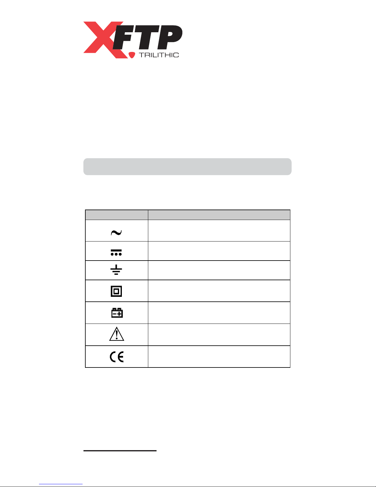
International Electrical Symbols
The following table describes the International Electrical
Symbols that are used on the device and manual.
• Turn the Meter power off when it is not in use and
take out the battery when not using for an
extended period.
• Constantly check the battery as it may leak when
it has been in extended use. Replace the battery
as soon as leaking is detected. A leaking battery
will damage the Meter.
Position Function
AC (Alternating Current)
DC (Direct Current)
Grounding
Double Insulated
Deficiency of Built-In Battery
Warning: Refer to Operation
Manual
Conforms to standards of the
European Union
Table of contents
Popular Multimeter manuals by other brands


Gossen MetraWatt
Gossen MetraWatt METRAmax 6 operating instructions

PeakTech
PeakTech 4000 Procedure of calibration

YOKOGAWA
YOKOGAWA 90050B user manual

Gossen MetraWatt
Gossen MetraWatt METRALINE DMM16 operating instructions

Fluke
Fluke 8846A Programmer's manual

Tempo Communications
Tempo Communications MM200 instruction manual


