Pfaff 571 Guide

ADJUSTMENT MANUAL
296-12-19 233/002
Justieranleitung engl. 10.14
This Adjustment Manual is valid for machines
from the following serial numbers onwards:
# 7 250 050
571
574
Industrial
®
591

The reprinting, copying or translation of PFAFF Adjustment Manuals, whether in whole or
in part, is only permitted with our previous authorization and with written reference to the
source.
PFAFF Industriesysteme
und Maschinen AG
Hans-Geiger-Str. 12 - IG Nord
D-67661 Kaiserslautern

Contents ..................................................................................Page
1Adjustment ........................................................................................................................... 6
1.01 Tools, gauges and other accessories .................................................................................... 6
1.02 Abbreviations ......................................................................................................................... 6
1.03 Explanation of the symbols.................................................................................................... 6
1.04 Adjusting the basic machine .................................................................................................. 7
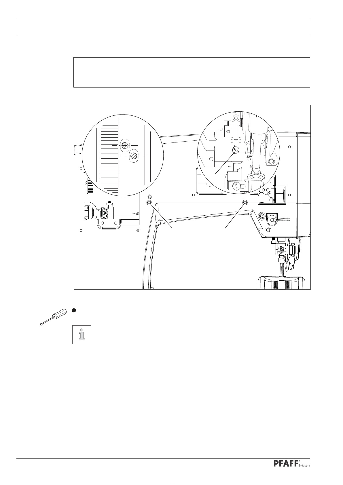
1.04.01 Needle position in sewing direction (on the PFAFF 571 and 591) ......................................... 7
1.04.02 Needle position in sewing direction (on the PFAFF 574)........................................................ 8
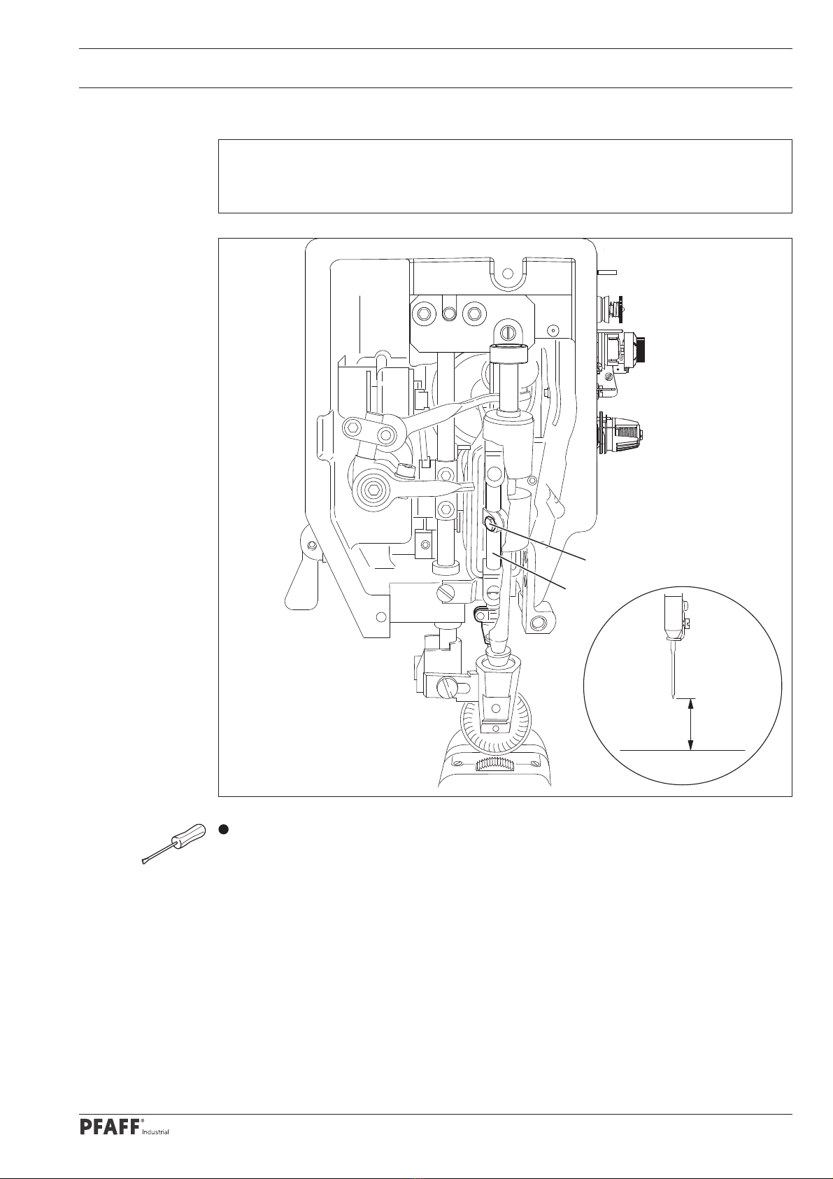
1.04.03 Preliminary adjustment of the needle height......................................................................... 9
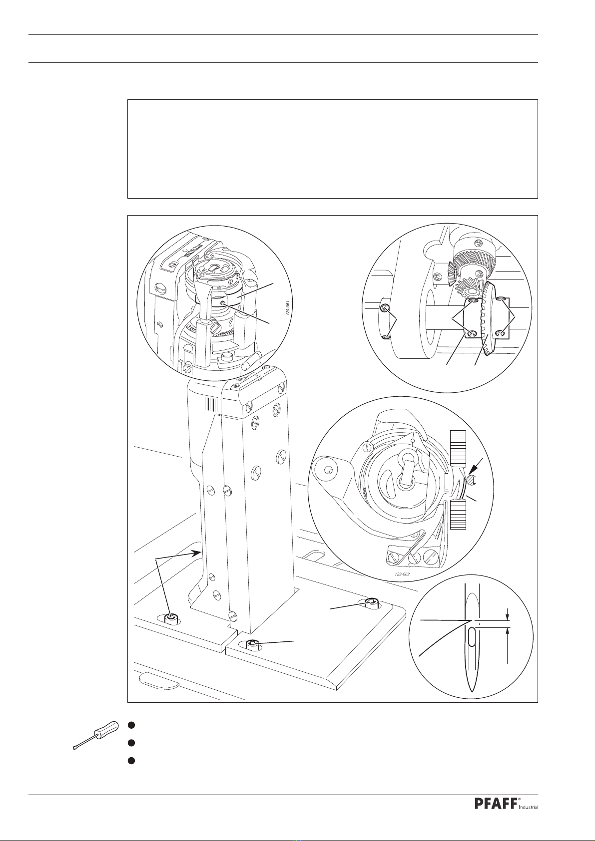
1.04.04 Needle rise, hook clearance, needle height and needle guard (on the PFAFF 571)................. 10
1.04.05 Needle rise, hook clearance, needle height and needle guard (on the PFAFF 574) .................12
1.04.06 Needle rise, hook clearance, needle height and needle guard (on the PFAFF 591).................14
1.04.07 Needle position crosswise to sewing direction (on the PFAFF 571).................................... 16
1.04.08 Needle position crosswise to sewing direction (on the PFAFF 574) .................................... 17
1.04.09 Needle position crosswise to sewing direction (on the PFAFF 591).................................... 18
1.04.10 Height and stroke of the bobbin case opener...................................................................... 19
1.04.11 Height of the feed wheel (on the PFAFF 571)...................................................................... 20
1.04.12 Height of the feed wheel (on the PFAFF 574) ...................................................................... 21
1.04.13 Height of the feed wheel (on the PFAFF 591)...................................................................... 22
1.04.14 Stitch length control eccentric ............................................................................................. 23
1.04.15 Stitch length scale disk ........................................................................................................ 24
1.04.16 Shaft crank to feed wheel drive ........................................................................................... 25
1.04.17 Shaft crank to roller presser drive ........................................................................................ 26
1.04.18 Clearance between roller presser and feed wheel .............................................................. 27
1.04.19 Roller presser....................................................................................................................... 28
1.04.20 Stitch length on stitch length scale ...................................................................................... 29
1.04.21 Synchronization of roller presser and feed wheel ................................................................ 30
1.04.22 Retainer (only on model 574) ............................................................................................... 31
1.04.23 Knee lever ............................................................................................................................ 32
Index

Contents ..................................................................................Page
1.04.24 Needle thread tension release............................................................................................. 33
1.04.25 Thread check spring (PFAFF 571 and 591) ........................................................................... 34
1.04.26 Thread check springs (PFAFF 574) ....................................................................................... 35
1.04.27 Bobbin winder...................................................................................................................... 36
1.04.28 Pressure of roller presser..................................................................................................... 37
1.04.29 Lubrication ........................................................................................................................... 38
1.04.30 Re-engage safety coupling................................................................................................... 39
1.05 Adjusting the edge trimmer -725/04.................................................................................... 40
1.05.01 Position of the knife holder (on model 571) ......................................................................... 40
1.05.02 Position of the knife holder (on model 591) ........................................................................ 41
1.05.03 Knife stroke (on model 571)................................................................................................. 42
1.05.04 Knife stroke (on model 591) ................................................................................................. 43
1.05.05 Cutting stroke (on model 571) ............................................................................................. 44
1.05.06 Cutting stroke (on model 591) ............................................................................................. 45
1.05.07 Knife position ....................................................................................................................... 46
1.06 Adjusting the thread trimmer -900/83.................................................................................. 47
1.06.01 Resting position of the roller lever / radial position of the control cam................................ 47
1.06.02 Position of the thread catcher holder ...................................................................................48
1.06.03 Position of the thread catcher .............................................................................................. 49
1.06.04 Knife position and knife pressure......................................................................................... 50
1.06.05 Bobbin thread retaining spring............................................................................................. 51
1.06.06 Manual cutting test .............................................................................................................. 52
1.06.07 Releasing the tension .......................................................................................................... 53
1.06.08 Linkage rod (only for the PFAFF 574) ................................................................................... 54
1.07 Adjustment of backtacking mechanism -911/....................................................................... 55
1.07.01 Needle in needle hole (only for PFAFF 571 and 591) ........................................................... 55
1.07.02 Couping for roller presser drive ......................................................................................... ..56
57
1.07.03 Adjusting the roller presser drive .........................................................................................
Index

Contents ..................................................................................Page
1.07.04 ......................................................................................... 58
1.07.05
Bevel gears for feed wheel drive
....................................................................... 59
1.07.06 Adjusting the magnets for feed wheel drive (-725/04)
Adjusting the magnets for feed wheel drive
........................................................ 60
1.08 Parameter settings .............................................................................................................. 61
1.08.01 Parameter list....................................................................................................................... 61
2Circuit diagrams ................................................................................................................ 63
2.01 Reference list for the Circuit diagrams 91-191 524-95 and 91-191 534-95 .......................... 63
2.02 Block diagram PFAFF 570 / 590 with control unit P40 ED .................................................. 65
2.03 Circuit diagrams 91-191 524-95 .......................................................................................... 66
2.04 Block diagram PFAFF 570 / 590 with control unit P44 PD-L ................................................ 68
2.05 Circuit diagrams 91-191 534-95 ......................................................................................... 69
Index

6
1 Adjustment
Please observe all notes from Chapter 1Safety of the instruction manual!
In particular care must be taken to see that all protective devices are refitted
properly after adjustment, see Chapter 1.06 Danger warnings of the instruc-
tion manual!
If not otherwise stated, the machine must be disconnected from the electrical
power supply. Danger of injury due to unintentional starting of the machine!
Notes on adjustment
All following adjustments are based on a fully assembled machine and may only be carried
out by expert staff trained for this purpose.
Machine covers, which have to be removed and replaced to carry out checks and adjust-
ments, are not mentioned in the text.
The order of the following chapters corresponds to the most logical work sequence for
machines which have to be completely adjusted. If only specific individual work steps are
carried out, both the preceding and following chapters must be observed.
Screws, nuts indicated in brackets ( ) are fastenings for machine parts, which must be
loosened before adjustment and tightened again afterwards.
1.01 Tools, gauges and other accessories
1set of screwdrivers with blade widths from 2to 10 mm
1set of open-ended wrenches with opening sizes from 7to 13 mm
1set of allen keys from 1.5to 6mm
1clamp (Order No. 08-880 137-00)
1metal rule (Order No. 08-880 218-00)
1gauge (Order No. 08-880 136-01)
Sewing thread and test material
1.02 Abbreviations
TDC = top dead center
BDC = bottom dead center
1.03 Explanation of the symbols
In this adjustment manual, symbols emphasize operations to be carried out or important in-
formation. The symbols used have the following meaning:
Note, information
Service, repair, adjustment, maintenance
(work to be carried out by qualified staff only)
Adjustment

7
21
Fig. 1 - 01
1.04 Adjusting the basic machine
1.04.01 Needle position in sewing direction (on the PFAFF 571 and 591)
Set the minimum stitch length.
Adjust needle bar (screw 1) according to the requirement.
Requirement
With the stitch length set at its minimum, the needle should be positioned in the centre
of the needle hole, as seen in the direction of sewing.
1
Adjustment

8
1.04.02 Needle position in sewing direction (on the PFAFF 574)
Requirement
The needle should be positioned in the centre of the needle hole as seen in the direction
of sewing.
Adjust needle bar (screws 1and 2) according to the requirement.
2
2
1
Screws 2are accessible through the holes on the back of the housing.
Fig. 1-02
Adjustment

9
1.04.03 Preliminary adjustment of the needle height
Requirement
When the needle bar is at TDC, there must be a clearance of approx. 21 mm between the
needle point and the needle plate.
Adjust needle bar 1(screw 2), without turning it, according to the requirement.
90-036
Fig. 1 - 03
2
1
21 mm
Adjustment

10
1.04.04 Needle rise, hook clearance, needle height and needle guard (on the PFAFF 571)
Requirement
With the needle bar positioned 2,4mm after BDC and the stitch length set at "0"
the hook point must be at needle centre with a hook-to-needle clearance of
0.05 to 0.1mm;
the top of the needle eye must be 0.8to 1.0mm below the hook point;
the needle guard 6must touch the needle lightly.
1.
2.
3.
Set stitch length at "0".
Loosen both screws 1, 2, 3, 4and 5.
Bring needle bar to 2.4mm past BDC:
61-023
Fig. 1 - 04
1
23
78
4
5
5
0,8 - 1 mm
6
9
6
Adjustment

11
Set hook point at needle centre, making sure that the needle is not deflected by needle
guard 6.
Adjust needle height according to Requirement 2.
Adjust hook post according to Requirement 1and tighten screws 4and 5.
Making sure that there is some play in the bevel gear, tighten screws 1.
With retaining collar 7touching bevel gear 8tighten screws 2and 3.
Adjust needle guard 6(screw 9) according to requirement 3.
When the hook is changed, make sure that
the markings 10 and 11 are both on one side. 10
11
Adjustment

12
1.04.05 Needle rise, hook clearance, needle height and needle guard (on the PFAFF 574)
Requirement
In needle rise position 2.4 mm after B.D.C, on both hooks
the hook point must be at needle centre with a hook-to-needle clearance of
0.05 to 0.1mm;
the top of the needle eye must be 0.8to 1.0mm below the hook points;
the needle guard 9must touch the needle lightly.
1.
2.
3.
61-025
Fig. 1 - 05
3
7
8
456
0,8 - 1 mm
8
12
12
10 11 13
77
7
8
129-002
9
100-921
14
9
Adjustment

13
Loosen screws 1, 2, 3, 4, 5, 6and 7.
Loosen screws 8slightly.
Bring the needle bar into needle rise position 2.4 mm after BDC.
Set both hook points at needle centre, making sure that the needles are not deflected by
needle guard 9.
Adjust needle height according to Requirement 2.
Adjust both hook posts according to Requirement 1and tighten screws 8.
Tighten screws 1and 6.
Making sure that there is some play in the bevel gear, tighten screws 3and 5.
With retaining collar 10 touching bevel gear 11 tighten screws 2.
With retaining collar 12 touching bevel gear 13 tighten screws 4.
Tighten screws 7on both sides of the post.
Adjust needle guard 9(screw 14) on both hooks according to rRquirement 3.
When a hook is changed, make sure that
the markings 15 and 16 are both on one side.
15
16
Adjustment

14
1.04.06 Needle rise, hook clearance, needle height and needle guard (onthe PFAFF 591)
Requirement
In needle rise position 2.4 mm after B.D.C, and with the stitch length set at "0"
the hook point must be at needle centre with a hook-to-needle clearance of
0.05 to 0.1mm;
the top of the needle eye must be 0.8to 1.0mm below the hook point;
the needle guard 6must touch the needle lightly.
1.
2.
3.
Adjustment
Fig. 1 - 06
6
9
4
5
5
0,8 - 1 mm
61-028
1
4
3
7
8
2

15
Set stitch length at "0".
Loosen screws 1, 2, 3, 4and 5.
Bring the needle bar into needle rise position 2.4 mm after B.D.C.
Set hook point at needle centre, making sure that the needle is not deflected by needle
guard 6.
Adjust needle height according to Requirement 2.
Adjust hook post according to Requirement 1and tighten screws 4.
Making sure that there is some play in the bevel gear, tighten screws 2.
With retaining collar 7touching bevel gear 8tighten screws 1.
Screws 5remain loosened for further adjustments.
Adjust needle guard 6(screw 9) according to Requirement 3..
When the hook is changed, make sure
that the markings 10 and 11 are both
on one side. 10
11
Adjustment

16
1.04.07 Needle position crosswise to sewing direction (on the PFAFF 571)
Requirement
When the stitch length is set at its maximum, the needle must be positioned in the cen-
tre of the needle hole when entering and coming out of the needle plate.
Turn screws 1(screws 2, on both sides of the post) according to the requirement.
2
61-029
2
2
2
Fig. 1 - 07
Adjustment

17
1.04.08 Needle position crosswise to sewing direction (on the PFAFF 574)
Shift bearing plate 1(screws 2, on both sides of the post) according to the requirement.
Requirement
As seen crosswise to the sewing direction, the needles must penetrate in the centre of
their needle holes.
Fig. 1 - 08
1
2
2
2
2
Adjustment

18
1.04.09 Needle position crosswise to sewing direction (on the PFAFF 591)
Requirement
As seen crosswise to the sewing direction, the needle must penetrate in the centre of
the needle hole.
Adjust feed wheel post 1(screws 2, 3and 4) according to the requirement.
90-035
Fig. 1 - 09
3
1
2
4
4
4
2
Adjustment

19
1.04.10 Height and stroke of the bobbin case opener
Requirement
The top edges of the bobbin case opener 1and bobbin case base 3should be on one
level.
When the bobbin case opener 1has deflected the bobbin case to its furthest point, the
catch of the bobbin case should be 0.3– 0.5mm from the back edge of the needle plate
recess.
1.
2.
Adjust bobbin case opener 1(screw 2) in accordance with requirement 1.
Turn the balance wheel until the bobbin case opener has deflected the bobbin case to its
furthest point.
Adjust bobbin case opener 1(screw 2) in accordance with requirement 2.
On the PFAFF 574 these adjustments must be repeated on the right post.
Depending on the thread size, a variation of the setting in Requirement 2is
permitted.
1
2
700-921
0,3 - 0,5 mm
600-921
3
1
Fig. 1 - 10
Adjustment

20
1.04.11 Height of the feed wheel (on the PFAFF 571)
Requirement
When pressure is applied to the feed wheel 4, it should protrude from the needle plate
by tooth height (approx. 0.8mm)
When no pressure is applied to the feed wheel 4, it should have a vertical play of ap-
prox. 0.3mm.
1.
2.
Swing out the roller presser.
Loosen screws 1and 2.
Adjust drive wheel 3according to requirement 1, taking care to see that the teeth of
drive wheel 3and feed wheel 4lock into each other properly.
Tighten screws 1.
Adjust guide 5according to requirement 2and tighten screws 2.
Fig. 1 - 11
2
1
5
3
4
0,8 mm
0,3 mm
1
Adjustment
Other manuals for 571
5
This manual suits for next models
2
Table of contents
Other Pfaff Sewing Machine manuals

Pfaff
Pfaff 3568-2/12 User manual

Pfaff
Pfaff tipmatic tiptronic 1151 User manual

Pfaff
Pfaff 1245 User manual

Pfaff
Pfaff 1196 User manual

Pfaff
Pfaff Hobby 301 User manual

Pfaff
Pfaff 918 User manual

Pfaff
Pfaff 5480 series User manual

Pfaff
Pfaff creative 1469 User manual

Pfaff
Pfaff dorina 72 User manual

Pfaff
Pfaff FREESTYLE 1527 User manual