Pfaff Series 3701 Owner's manual

296-12-18 959/002
engl. 06.09
Supplement to the instruction
manual and parts list for the
series 1180, 3701, 5483
-948/26

The reprinting, copying or translation of PFAFF Instruction Manuals, whether in whole or
in part, is only permitted with our previous authorization and with written reference to the
source.
PFAFF Industriesysteme
und Maschinen AG
Hans-Geiger-Str. 12 - IG Nord
D-67661 Kaiserslautern

Index
Contents ................................................................................................. Page
1Proper use ........................................................................................................................... 4
1.01 Using standard presser feet ................................................................................................. 4
2Controls .............................................................................................................................. 5
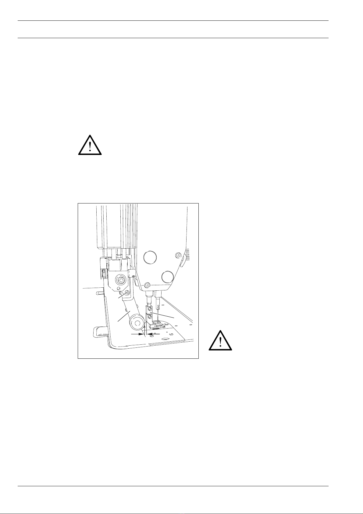
2.01 Puller functions .................................................................................................................... 5
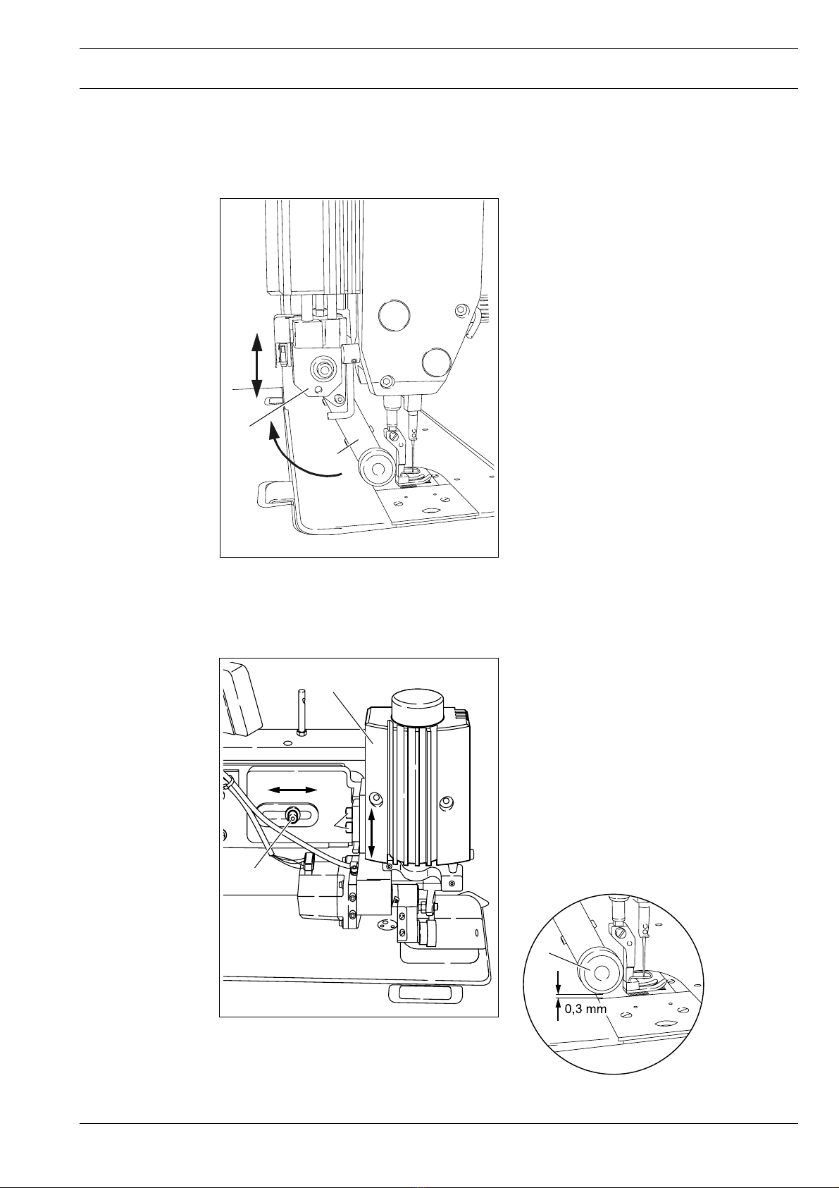
2.02 Aligning the puller ................................................................................................................ 5
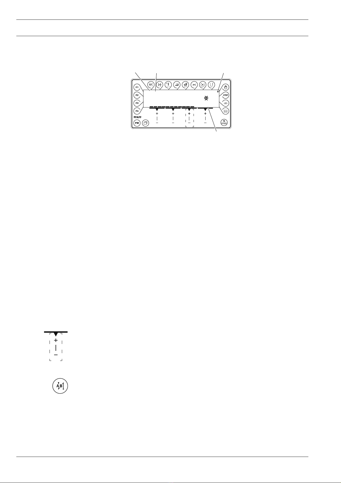
2.03 Control panel ........................................................................................................................ 6
2.03.01 Screen displays .................................................................................................................... 6
2.03.02 Function keys ....................................................................................................................... 6
2.03.03 Selecting and altering parameters ........................................................................................ 9
2.03.04 Selecting the user level ...................................................................................................... 10
3Commissioning ................................................................................................................ 11
3.01 Basic position of the machine drive ................................................................................... 11
3.02 Testing the function of the start inhibitor ........................................................................... 12
4Setting up ......................................................................................................................... 13
4.01 Entering the puller feed stroke (stitch length) .................................................................... 13
4.02 Setting the puller pressure ................................................................................................. 13
4.03 Entering the maximum speed ............................................................................................ 14
4.04 Entering the start and end backtacks ................................................................................. 14
4.05 Setting the stitch counting function for the bobbin thread control ..................................... 15
5Sewing ................................................................................................................................ 1
5.01 Manual sewing ..................................................................................................................... 1
5.02 Programmed sewing ............................................................................................................2
5.03 Error messages .................................................................................................................... 3
6Parameter Settings ........................................................................................................... 16
7Software-Update .............................................................................................................. 21
8Reset / Kaltstart ................................................................................................................ 22
9Partslist ............................................................................................................................. 23
10 Circuit diagrams ............................................................................................................... 24

Proper use
4
1 Proper use
With the puller the workpiece is fed continously, which makes it possible to sew to a great
extent without shifting and puckering. The puller’s linear motor enables an individual
clearance space between the needle plate and the puller roller.
All adjustments, such as e.g. puller feed stroke, puller roller clearance etc. are carried out by
altering the parameter values, see Chapter 2.03.03 Selecting and altering parameters.
Any use of these machines which is not approved by the manufacturer shall be
considered as improper use! The manufacturer shall not be liable for any dam-
age arising out of improper use! Proper use shall also be considered to include
compliance with the operation, adjustment, service and repair measures speci-
fied by the manufacturer!
1.01 Using standard presser feet
●With the adapter 1which belongs to the
accessories, standard presser feed can
also be used
(Ordering number 91-154 790-22).
●Mount adapter 1as shown in Fig. 1-01.
●Loosen screw 2 and push puller arm 3
back.
●Screw the presser foot onto adapter 1.
●Adjust puller arm 3 so that there is a
clearance of approx. 1 mm between the
puller roller and the presser foot.
●Tighten screw 2.
When using the adapter, the
height of the puller roller must
be adjusted as described in
Chapter 2.02.
Fig. 1 - 01
1
2
1 mm
3

Controls
5
2 Controls
2.01 Puller functions
Engaging/disengaging the puller
●Raise the puller drive unit 1until it locks
into place and swing puller arm 2back as
far as possible. To engage the puller,
follow the instructions in the reverse
order.
Switching the puller on/off
●The puller is automatically switched on or
off when the puller unit is engaged or
disengaged.
Setting the puller feed motion
●The feed motion of the puller is set by
means of parameters (see Chap. 1.06
Parameter settings and the Motor
Instruction Manual)
Fig. 2 - 01
1
2
2.02 Aligning the puller
Puller crosswise to sewing direction
●Loosen screw 1.
●Align puller 2to the seam.
●Tighten screw 1.
Height of the puller roller
●Loosen screw 3
●Align puller 2, so that there is a clearance
of approx. 0.3 mm between the puller
roller 4and the cloth plate.
●Tighten screw 3.
4
Fig. 2 - 02
1
2
3

Controls
6
2.03 Control panel
The control panel consists of display 1and the function keys described below. Display 1
consists of a two-row, alpha-numerical display with 16 symbols per row. The texts 3show
the respective status of the function keys and the operating modes of the machine.
During the power-on phase the control panel automatically switches on all LCD segments
and the horn. The number of the version of the installed software then appears on the
display, until the higher-ranking control unit sends commands to the control panel.
2.03.01 Screen displays
●Activated functions are displayed with a triangular marking 2below or next to the
respective function key.
●In the sewing mode all relevant sewing data is displayed and these can be changed
directly, depending on the status of the machine, see also Chapter 5 Sewing.
●During the parameter input the selected parameter number with the corresponding value
is displayed, see Chapter 2.02.03 Selecting/changing parameters.
2.03.02 Function keys
The function keys described below are used basically to switch machine functions on and
off.
If a corresponding value has to be set for the activated function, this is carried out with the
corresponding +/- key. By pressing and holding the corresponding +/- key, the appropriate
numerical value 4is changed slowly to begin with. If the corresponding +/- key is held down
longer, the values change more quickly.
Start backtacks
If this key is pressed, the backtacks at the beginning of the seam (start backtacks) are
switched on or off. The number of forward stitches (A) or reverse stitches (B) for the start
backtacks can be changed by pressing the +/- key underneath. To convert from double
backtack to single backtack set the corresponding number of stitches at zero.
4000 PUL 30%
2.0mm
Speed
3
12
4

Controls
7
End backtacks
●If this key is pressed, the backtacks at the end of the seam (end backtacks) are switched
on or off. The number of reverse stitches (C) or forward stitches (D) can be changed by
pressing the +/- key underneath. To convert from double backtack to single backtack set
the corresponding number of stitches at zero.
Needle position
●If this key is pressed the corresponding function is switched on or off. When the function
is switched on, the needle positions at t.d.c. after sewing stops.
Foot position after stop
●If this key is pressed the corresponding function is switched on or off. When the function
is switched on, the presser foot is raised after sewing stops.
Foot position after trimming
●If this key is pressed the corresponding function is switched on or off. When the function
is switched on, the presser foot is raised after thread trimming.
Thread trimmer
●If this key is pressed the thread trimming function is switched on or off.
Speed (only in programmed sewing)
●If this key is pressed the corresponding function is switched on or off. In the seam
program the speed is not dependent on the pedal. When the function is switched on, the
speed cannot be adjusted by pedal. Sewing can only be carried out at the set maximum
speed.
●If the function is switched off, the speed up to maximum speed is adjusted by the pedal.
Reverse sewing
●If this key is pressed the corresponding function is switched on or off. When the function
is switched during programmed sewing, the corresponding seam section is sewn in
reverse.
Manual seam (only in programmed sewing)
●If this key is pressed the machine switches to manual sewing. When the function is
switched on, the move to the next seam section is not carried out by stitch counting or
sensor, but manually with the use of the pedal (position "-2").
Stop
●If this key is pressed the corresponding function is switched on or off. When the function
is switched on, the machine stops automatically at the end of a seam section.
Sensor
●In manual sewing the number of compensating stitches from the point where the
photocell is light to the end of the seam can be set under parameter 111, and in
programmed sewing directly.

Controls
8
Stitch counting
●If this key is pressed the corresponding function is switched on or off. When the function
is switched on, the machine moves to the next seam section after sewing the number of
stitches entered.
TE/Speed
●In the programmed sewing mode, the number of stitches is entered by stitching them off.
●If this key is pressed once, the machine changes to parameter input.
●If this key is pressed twice (within 5 seconds) the machine changes to stitch input.
Scrolling
●If this key is pressed in the programmed sewing mode, the machine scrolls through the
input menus on the display.
PM
●If this key is pressed the programmed sewing function is switched on or off. When the
function is switched on, the letters "PM" appear on the display of the control panel. The
parameters related to the program are shown in the alpha-numerical part of the display.
F1
No function assigned
F2
No function assigned
F3
No function assigned
F4
No function assigned

Controls
9
No
No
No
A 600
TE
No VAL
A 101 OFF
TE
No VAL
A 660 1
TE
No VAL
A 660 2
TE
VAL
2.03.03 Selecting and altering parameters
●Switch on the machine.
●Press the TE/Speed key to call up the parameter input function.
●By pressing the corresponding +/- key select the desired parameter, e.g. "660" for the
bobbin thread monitoring function.
●By pressing the corresponding +/- key select the desired parameter group, e.g. "600".
●Press the TE/Speed key to take over the value and change to the sewing mode.
●By pressing the corresponding +/- key set the desired value for the parameter selected,
e.g. "2" for the "bobbin rest thread counter on" function.

Controls
10
No
No
VAL
2.03.04 Selecting the user level
●Switch on the machine.
●Press the TE/Speed key to call up the parameter input function.
●By pressing the corresponding +/- key select the parameter "798".
●By pressing the corresponding +/- key select the parameter group "700".
●By pressing the corresponding +/- key select the desired user level:
"0" = operator level A
"1" = technician level B
"11" = service level C
The respective level is displayed on the screen. (see arrow)
●Press the TE/Speed key to take over the value and change to the sewing mode.
No
A 798 0
TE
No
A 101
TE
No VAL
798 1
TE
B

Commissioning
11
No
B
●Press the TE/Speed key to call up the parameter input function.
●Select the technician level B(value "1") with parameter "798", see Chapter 2.03.04
Selecting the user level.
●By pressing the corresponding +/- key select the parameter group "700".
●Sew a stitch by operating the pedal.
●Turn the balance wheel in the direction of sewing until the needle point is level with the
top edge of the needle plate.
●Press the TE/Speed key to take over the setting and to conclude the input.
3 Commissioning
3.01 Basic position of the machine drive
●Switch on the machine.
4000 PUL 30%
2.0mm
Speed
No
700 0
TE
B
B
No VAL
798 1
TE

Commissioning
12
3.02 Testing the function of the start inhibitor
●Switch the machine on at the main switch and tilt back the sewing head.
The error message "9" must appear on the control panel.
●If the message does not appear, check the setting of the safety switch
(in the machine instruction manual).
●Set the sewing head upright again and acknowledge the error message by pressing the
TE/Speed key. The machine is ready for operation again.
9
PRESS TE/SPEED
ERROR

Setting up
13
4 Setting up
4.01 Entering the puller feed stroke (stitch length)
●Switch on the machine.
●Enter the feed stroke by pressing the corresponding +/- key.
The puller feed stroke setting must match the stitch length setting of the basic
machine!
4.02 Setting the puller pressure
●Switch on the machine.
●Set the desired puller pressure by pressing the corresponding +/- key.
The value for the current puller pressure (in %) can be read on the display.
4000 PUL 30%
2.0mm
Speed
4000 PUL 30%
2.0mm
Speed

Setting up
14
4.04 Entering the start and end backtacks
●Switch on the machine.
●Press the TE/Speed key twice to select the input menu for start and end backtacks.
4.03 Entering the maximum speed
●Switch on the machine.
●Enter the maximum speed by pressing the corresponding +/- key.
A
B
C
D
●By pressing the corresponding +/- key select the desired value for the number of forward
stitches (A) of the start backtack.
●By pressing the corresponding +/- key select the desired value for the number of reverse
stitches (B) of the start backtack.
●By pressing the corresponding +/- key select the desired value for the number of reverse
stitches (C) of the end backtack.
●By pressing the corresponding +/- key select the desired value for the number of forward
stitches (D) of the end backtack.
4000 PUL 30%
2.0mm
Speed
The max. speed is limited with parameter 607.
2 x
In the programmed sewing mode it is possible to call up the input menu for
start and end backtacks by pressing the scroll key, see Chapter 5.02
Programmed sewing.
AB C D
3333
PM

Setting up
15
No VAL
760 5
TE
4.05 Setting the stitch counting function for the bobbin thread control
●Switch on the machine.
●Press the TE/Speed key to call up the parameter input function.
●By pressing the corresponding +/- key select the parameter "760".No
●Press the corresponding +/- key to set the number of remaining stitches, which can still
be sewn after recognition by the bobbin thread control function.
The selected value is multiplied by 10* or 200** and the result is the number of stitches.
Example display 5 x 200** = 1000 stitches. The setting depends among other things on
the thread strength.
●If the TE/Speed key is pressed, the value is taken over and the machine changes into the
sewing mode.
The bobbin thread rest counter can only be used, if parameter "660" is set at
value "1" or "2".
*If for parameter 660 the value is "1", the multiplier is 10
** If for parameter 660 the value is "2", the multiplier is 200
VAL
No VAL
101 ON
TE
A
A

Sewing
16
5 Sewing
In the sewing mode all relevant adjustments for the sewing operation are shown on the
display and can be altered directly. Functions can be switched on and off by pressing the
key.
In this mode a difference is made between manual sewing and programmed sewing. To
change from manual to programmed sewing, press the PM key. In programmed sewing the
text "PM" appears on the display.
5.01 Manual sewing
After the machine has been switched on, the maximum speed, the puller feed stroke and
the puller pressure can be adjusted with the corresponding +/- keys.
Further functions in manual sewing, also see Chapter 2.02.02Function keys:
Start backtacks on/off Presser foot raised at end of seam on/off
End backtacks on/off Thread trimming on/off
Needle position raised on/off Sensor on/off
Presser foot raised on/off
On the basic machine the stitch length is adjusted with the balance wheel.
The stitch length for the puller is adjusted on the control panel
4000 PUL 30%
2.0mm
Speed

Sewing
17
5.02 Programmed sewing
In the programmed sewing mode 99 programs, each with 9 seam sections and 999 stitches,
can be programmed.
The fixed programs are used for the quick and easy production of seams with different
numbers of stitches. The pedal setting „0“ is used to switch to the next seam section.
After the machine has been switched on and the programmed sewing mode has been
selected with the PM key, the display appears for selecting the program number, seam
section and number of stitches.
With the scroll key other menus can be selected for entering the values for start and end
backtacks and the maximum speed in the corresponding seam section.
Further functions in programmed sewing, also see Chapter 2.02.02 Function keys:
Start backtacks on/off Seam section speed on/off
End backtacks on/off Reverse sewing direction on/off
Needle position raised on/off Manual sewing on/off
Presser foot raised on/off Stop on/off
Presser foot raised after Sensor on/off
thread trimming on/off
Thread trimming on/off Stitch count on/off
11 13
PM
current
program number
current seam segment number of stitches
1000 5 0
PM
speed
in current
seam segment
number
of seam segments
program number
of linked program

Sewing
18
5.03 Error messages
If a fault occurs, the text "ERROR" appears on the display, together with an error code and
short instructions. An error message is caused by incorrect settings, faulty elements or
seam programs as well as by overload conditions.
●Correct the error.
●Acknowledge error correction by pressing the TE/Speed key.
ERROR
9
PRESS TE/SPEED

Parameter Settings
19
2 252 Puller roller clearance B, C 5 - 200 30
for start backtack ca. 4 mm
254 Puller roller clearance after trimming ca. 7mm B, C 10 - 255 50
3 302 Holding power of puller roller when rising B, C 50 - 200 140
318 Puller lifts with automatic presser foot lift and B, C 0 - 99 1
starts with a delay depending on parameter
445. 1 = on, 0 = off.
4 445 No. of stitches before puller B, C 0 - 99 0
roller touches down after machine start
(Only when 318 is set at "1")
499 Stitches for puller delay after knee switch A, B, C 0 - 99 0
6 607 Maximum speed B, C 300 - 6000 ▲
660 Bobbin thread monitoring A, B, C 0 - 2 0
0 = 0ff
1=by sensor (-926/06)
2=by stitch counting
7 700 Needle position 0 B, C 0 - 255 *
(needle reference position
702 Needle position 1 (needle lowered) B, C 0 - 255
1181, 1183, 3701 90
5483 100
703 Needle position 2 (take-up lever raised) B, C 0 - 255
1181, 1183, 3701 236
5483 208
760 Multiplier for the fixed value (200) for A, B, C 0 - 250 5
stitch count
799 Selected machine class C 1 - 3
1181, 3701 1
1183 2
5483 3
8 800 Rotating direction of the motor C 0 - 1
1181, 1183, 3701 0
5483 1
6 Parameter Settings
Group
Parameter
Description
Standard value
Adjustment
range
Access level

Parameter Settings
20
9 985 Switch on angle for thread trapper B, C 0 -255 67
986 Switch off angle for thread trapper B, C 0 -255 206
989 Thread trapper at beginning of seam B, C 0 - 2 0
1 = yes, 0 = no
10 1001 Stepping motor starting angle B, C 0 - 255
1181, 3701 25
1183 170
5483 144
1003 Feed roller radius C 5 - 50 15
11 1100 Operating mode stepping motor 1 C 0 - 2 1
1101 Rotation direction stepping motor 1 C 0 - 1 0
1 = anti-clockwise, 0 = clockwise
1102 Stepping mode stepping motor 1 C 0 - 4 3
1 = full-step, 2 = half-step,
3 = quarter step, 4 = eighth step
1103 Maximum current stepping motor in % C 0 - 100 50
1104 Reducing current stepping motor in % C 0 - 50 30
1105 Stepping motor 1, start-stop-time C 10 - 4000 180
(time for 1st step at start-stop-speed)
1106 Maximum speed stepping motor 1 C 10 - 4000 843
1107 Acceleration in % of max. speed on C 1 - 50 28
stepping motor 1
1108 Number of brake steps of stepping motor 1 C 1 - 50 5
1160 Feed motion compensation at beginning of seam A, B, C 0 - 99 20
The standard values listed in the table are basic settings, which can be
altered if necessary.
Further parameters are contained in the Motor Instruction Manual
VSee Chapter 3 Specifications in the machine Instruction Manual.
* Adjustment see Chapter 3.01 Basic position of the machine drive unit.
Group
Parameter
Description
Standard value
Adjustment
range
Access level
This manual suits for next models
6
Table of contents
Other Pfaff Sewing Machine manuals

Pfaff
Pfaff 212 User manual

Pfaff
Pfaff 463 User manual

Pfaff
Pfaff 1025 User manual

Pfaff
Pfaff 1425 User manual

Pfaff
Pfaff dorina 72 User manual

Pfaff
Pfaff Creative 7550 User manual

Pfaff
Pfaff 118 User manual

Pfaff
Pfaff 3371-10 series Guide

Pfaff
Pfaff STITCH CREATOR User manual

Pfaff
Pfaff EXPRESSION 2038 - User manual

Pfaff
Pfaff POWERline 2595 BASIC User manual

Pfaff
Pfaff 138 User manual

Pfaff
Pfaff 1571 Guide

Pfaff
Pfaff Creative Vision Manual

Pfaff
Pfaff 9063 User manual

Pfaff
Pfaff selectline User manual

Pfaff
Pfaff hobbylock 2.0 User manual

Pfaff
Pfaff 1571 User manual

Pfaff
Pfaff ClassicStyle 1525 User manual

Pfaff
Pfaff 3588-04/020 User manual