PFlow Industries 21 Series User manual

15707-0002 | Rev F | 2018-10-15 | Printed in the U.S.A.
21 Series | Hydraulic VRC
Owner’s Manual
Customer:
Job Number:
Important:
Read this entire manual.
Important safety information
is included.
The illustrations depicted in this manual
are not to scale or detail. The illustrations
are for reference only.
www.pflow.com
P 414 352 9000
F 414 352 9002
6720 N. Teutonia Ave.
Milwaukee, WI 53209

72&_ 6HULHV__5HY)__HPDLOSVG#SÁRZFRP
Table of Contents
www.pflow.com
P 414 352 9000
F 414 352 9002
6720 N. Teutonia Ave.
Milwaukee, WI 53209
Description Section | Page
1. Contact Information 15705-0011 1 | 1
2. General Information 15710-0004 2 | 1
Introduction 2 | 1
General Overview 2 | 1
Code Requirements 2 | 1
Parts 2 | 1
Service 2 | 1
Feedback 2 | 1
3. Warranty Information 15710-0014 3 | 1
Parts and Labor 3 | 1
'HÀQLWLRQV 3 | 1
Warranty 3 | 1
Exclusions 3 | 1
Obligation 3 | 1
Liability 3 | 2
Warranty Procedures 3 | 2
Pre-Authorization 3 | 2
Invoices 3 | 2
4. Important Safety Information 15707-0004 4 | 1
Read the Entire Manual 4 | 1
Intended Purpose 4 | 1
Safety Alert Symbols 4 | 1
Danger Statements 4 | 2
Warning Statements 4 | 2
Hydraulic Safety Precautions 4 | 4
Caution Statements 4 | 5
Electrical Safety Precautions 4 | 6
De-energize the Circuit 4 | 6
Electrical Safety Precautions 4 | 7
Working on Energized Circuits 4 | 7
Notes for the Installation Electrician 4 | 7
Entrance Below a Raised Carriage Deck 15709-0083 4 | 9
5. Glossary 15710-0018 5 | 1
Unique Descriptions and Names 5 | 1
Gate Types 5 | 8
Identifying Call Outs 5 | 9

Table of Contents
6HULHV__5HY)__HPDLOSVG#SÁRZFRP 72&_
www.pflow.com
P 414 352 9000
F 414 352 9002
6720 N. Teutonia Ave.
Milwaukee, WI 53209
Description Section | Page
(OHFWULFDO6WDQGDUGVDQG'HÀQLWLRQV 15709-0085 6 | 1
Field Electrical Wiring Standards 6 | 1
'HÀQLWLRQV 6 | 1
Requirements 6 | 1
Electrical Ruling Bodies 6 | 2
PFlow’s Standard 6 | 2
Outdoor Application 6 | 2
Corrosive Application 6 | 2
Hazardous Location 6 | 3
&ODVV'HÀQLWLRQV 6 | 3
'LYLVLRQ'HÀQLWLRQV 6 | 3
Group Designations 6 | 3
7. Mechanical Overview 15707-0009 7 | 1
Lift Columns 7 | 1
6WUDGGOH&DQWLOHYHU&RQÀJXUDWLRQ 7 | 1
Hydraulic Pump and Motor 7 | 2
Placement Considerations 7 | 2
Wheelblocks 7 | 3
Mechanical Stop 7 | 3
Hydraulic Cylinder 7 | 3
Velocity Fuse 7 | 3
Enclosures 7 | 4
Gate Assemblies 7 | 5
8. Electrical Overview 15709-0018 8 | 1
Main Control Panel 8 | 1
Push-button Stations 8 | 1
Main Disconnect 8 | 1
Hydraulic Pump and Motor 8 | 2
9. Sequence of Operation 15707-0010 9 | 1
Operation Safety Information 9 | 1
Sequence 9 | 2
To Operate the Lift 9 | 5

72&_ 6HULHV__5HY)__HPDLOSVG#SÁRZFRP
Table of Contents
www.pflow.com
P 414 352 9000
F 414 352 9002
6720 N. Teutonia Ave.
Milwaukee, WI 53209
Description Section | Page
10. Manual Lowering 15702-0008 10 | 1
Operation Safety Information 10 | 1
Emergency Use Only! 10 | 1
11. Cleaning 15709-0088 11 | 1
Safety Information 11 | 1
Cleaning 11 | 1
12. Preventive Maintenance and Schedule
Checklist
15707-0011 12 | 1
Safety Information 12 | 1
Hydraulic Safety Precautions 12 | 2
Checklist 12 | 3
Oil Environment 12 | 4
Oil Offered 12 | 4
Tools Needed 12 | 4
Change the Oil 12 | 4
Clean the Reservoir 12 | 5
Flush the Reservoir 12 | 6
13. Troubleshooting 15707-0012 13 | 1
14. Adjust Motor Overload Sensor 15702-0022 14 | 1
15. Recommended Spare Parts 15707-0013 15 | 1
16. Parts 15707-0014 16 | 1
Hydraulic Components 16 | 1
Carriage Stop 16 | 2
Jackscrew Assembly 16 | 2
Manifold Block Assembly 16 | 2
Hydraulic Pump and Motor 16 | 3
Chain Loop Arrangement 16 | 4
Interlocks 16 | 5
Gate Status Switches 16 | 7
Wheelblock Assembly 16 | 8
17. Recommended Storage Requirements 15709-0080-1 17 | 1
Environment 17 | 1
Stacking 17 | 1
Long Term Storage 17 | 1
Storage for Longer than Six Months 17 | 2
Equipment Manuals 17 | 2
18. Signage Locations 15709-0035 18 | 1
19. Installation Questionnaire 15708-1500 19 | 1
$FFHSWDQFH&HUWLÀFDWH95& 15710-0017-VRC 20 | 1

Table of Contents
6HULHV__5HY)__HPDLOSVG#SÁRZFRP 72&_
www.pflow.com
P 414 352 9000
F 414 352 9002
6720 N. Teutonia Ave.
Milwaukee, WI 53209
Safety Data Sheets
Description Document # Revision
Bill of Material Sheets
Document #
Option Drawings
Descriptions Document # Revision
Customer Information
Customer Name Job Number

72&_ 6HULHV__5HY)__HPDLOSVG#SÁRZFRP
Table of Contents
www.pflow.com
P 414 352 9000
F 414 352 9002
6720 N. Teutonia Ave.
Milwaukee, WI 53209
Customer Information
Customer Name Job Number
Job Drawings
Description Document # Revision
Electrical Drawings
Description Document # Revision

_5HY+__HPDLOSVG#SÁRZFRP 6HFWLRQ_
Section 1 | Contact Information www.pflow.com
P 414 352 9000
F 414 352 9002
6720 N. Teutonia Ave.
Milwaukee, WI 53209
PFlow Industries, Inc.
6720 N. Teutonia Avenue
Milwaukee, Wisconsin 53209
Oce
Phone: 414-352-9000
Fax: 414-352-9002
Product Support Department
e-mail: psd@pow.com
Sales
e-mail: sales@pow.com
For a list of contact personnel visit the PFlow Industries, Inc. website at:
http://www.pow.com/contact-us/
PFlow Industries, Inc. reserves the right to make changes or improvements to
the standard model line at any time. PFlow Industries, Inc. reserves the right
to make changes to subsequent editions of the manual without prior notice to
holders of this edition.
© Copyright April 2018 by PFlow Industries, Inc.
All rights reserved.
No part of this manual may be reproduced or used in any form without
expressed written permission from PFlow Industries, Inc.
This publication may be photocopied by the original purchaser of the
VRC. Any other type of reproduction is prohibited without express written
permission from PFlow Industries, Inc.
All trademarks referenced in this manual are the property of their
respectiveowners.
Mechanical or electrical modications performed on the VRC not approved
by PFlow Industries, Inc. may void any warranty and/or service agreements.
Please contact the PFlow Product Support Department for assistance with
service modications.
Training is available upon request from the Product Support Department.
Half-Day, Full-Day, and Two-Day sessions are customized to t specic needs -
either for a single VRC type or for the entire product line.
On-site supervision services are available from the Product Support
Department. Contact our Field Operations Manager for more details.
This manual is written in American English.
Documentation
Copyright Notice
Trademarks
Training
On-site Supervision
Source Language
System
0RGLÀFDWLRQV
Disclaimer

6HFWLRQ_ _5HY+__HPDLOSVG#SÁRZFRP
Section 1 | Contact Information www.pflow.com
P 414 352 9000
F 414 352 9002
6720 N. Teutonia Ave.
Milwaukee, WI 53209

_5HY&__HPDLOSVG#SÁRZFRP 6HFWLRQ_
Section 2 | General Information www.pflow.com
P 414 352 9000
F 414 352 9002
6720 N. Teutonia Ave.
Milwaukee, WI 53209
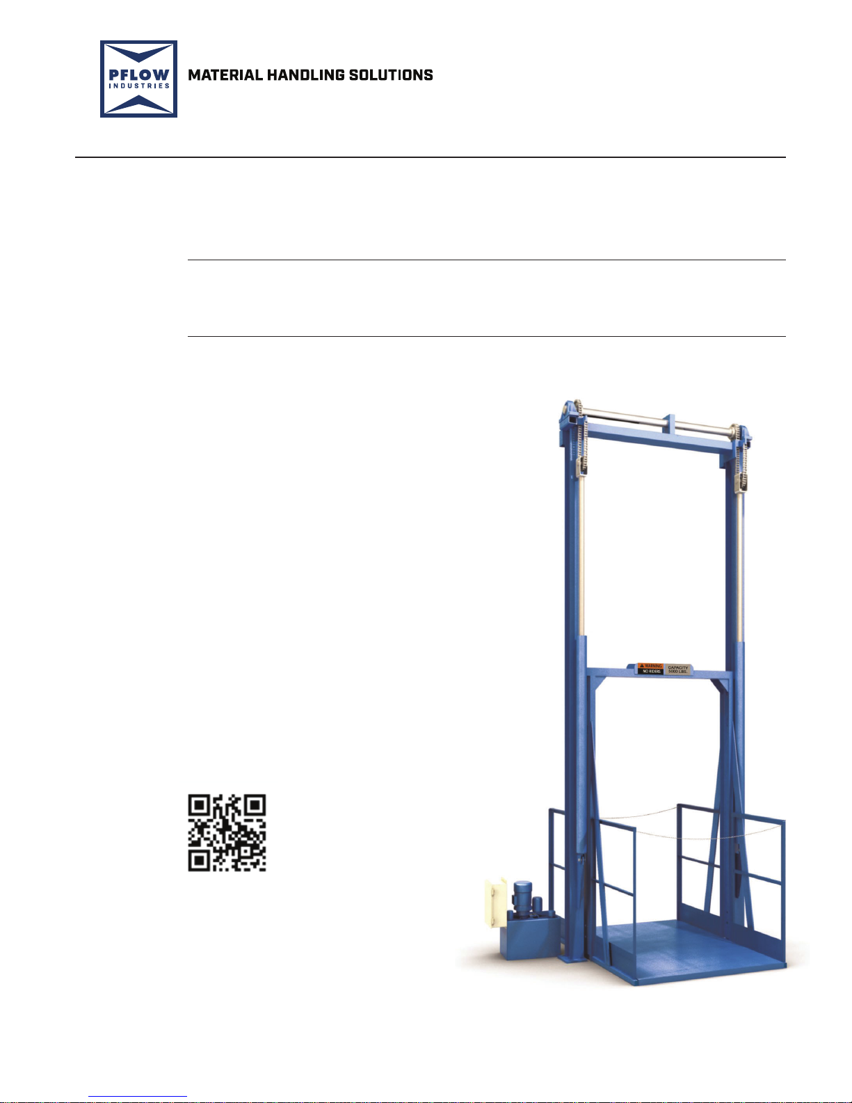
This manual provides information about the PFlow Industries, Inc. custom designed
Vertical Reciprocating Conveyor (VRC). As the nations’ leading manufacturer of
vertical material handling equipment, PFlow Industries, Inc. is condent that this
new VRC will provide many years of reliable service.
The VRC provides a safe and simple means of moving material from one level to
another. The simplicity of design and few moving components ensure a trouble-free,
long life, with low maintenance and little downtime.
This VRC is designed for the movement of materials only, up to the VRC’s rated capacity,
from one level to the next. Do not allow anyone to ride on the VRC. VRCs are not
elevators, and are specically excluded within the scope of the ASMEA17.1 Safety
Code for Elevators and Escalators. VRCs are included in ASMEB20.1 Safety Standard
for Conveyors and Related Equipment, which is incorporated by reference into OSHA
29 CFR 1910. A copy of the ASME B20.1 standard can be purchased at
www.asme.org and other sources. PFlow Industries, Inc. recommends that this
standard be referenced for appropriate installation, maintenance, inspection,
and operation in relation to hazards. All electrical designs and components are in
accordance with National Electric Code (NEC) requirements. Local codes may
require initial inspection of the installation and periodic inspection and testing of the
unit. Contact PFlow Industries, Inc. for more information in the event an inspection
is required.
The information and illustrations in this manual are intended only as an aid to understanding
the VRCs general installation. The information and illustrations do not cover every possible
contingency or circumstance regarding nonstandard options or siteconditions.
If there is a problem, call PFlow Industries, Inc. at (414) 352-9000, during normal
business hours, 8:30 a.m. to 5:00 p.m. central standard time, Monday through
Friday. Outside of those hours, see the PFlow Industries, Inc. Contact Information
page for additional information. Use the model number and serial number or the
PFlow Industries, Inc. General Arrangement (GA) drawing number for the li in
allcorrespondence.
Equipment damage resulting from modication in any manner from the original
model, including the substitution of parts other than factory authorized parts, will
void thewarranty. Furthermore, PFlow Industries, Inc. will not be liable for any loss,
injury, or damage to persons or property, nor for direct, indirect, or consequential
damage of any kind resulting from modied or substitution of parts other than
factory authorized parts of said material or equipment.
PFlow Industries, Inc. maintains a complete stock of, or has access to, all replacement
components. Detailed records of all equipment sold are kept. If a component is
damaged in shipment, is defective or missing, contact PFlow Industries immediately.
The PFlow Industries, Inc. Product Support Department will assist maintenance
and service personnel with any questions or problems regarding the equipment
orinstallation.
Your feedback is important. Please help PFlow Industries, Inc. understand if the
equipment has met your expectations. Please complete the questionnaire in this
manual. The questionnaire will help us address any comments and/or concerns.
Introduction
General
Overview
Code
Requirements
Parts
Service
Feedback
NOTE

6HFWLRQ_ _5HY&__HPDLOSVG#SÁRZFRP
Section 2 | General Information www.pflow.com
P 414 352 9000
F 414 352 9002
6720 N. Teutonia Ave.
Milwaukee, WI 53209

_5HY'__HPDLOSVG#SÁRZFRP 6HFWLRQ_
Section 3 | Warranty Information www.pflow.com
P 414 352 9000
F 414 352 9002
6720 N. Teutonia Ave.
Milwaukee, WI 53209
zStructure is dened as columns, carriage, and pre-fabricated bracing
(excluding carriage side guards).
zManufactured components are dened as those components manufactured
by PFlow Industries, Inc.
zPurchased components are those components that are used as supplied
byvendors.
PFlow Industries, Inc. expressly warrants to the original purchaser that this
product will be free from defects in material and workmanship under normal,
intended use. The warranty period begins 30 days aer shipment.
This warranty does not apply to:
1. Equipment or components damaged or broken in transit or shipping.
2. Replacement of wear parts.
3. Equipment failures caused by abuse, misuse, exceeding recommended
capacities, impact with other objects, negligence, improper installation,
unskilled use, unskilled maintenance, inadequate maintenance, or
incorrectadjustments.
4. Exposure to a corrosive or abrasive environment or exterior elements unless
specically built for that environment.
5. Equipment that has been repaired, altered or modied in any manner outside of
the manufacturing facility, substitution of parts other than factory authorized
parts, removal of any parts, or addition of any parts without prior written
permission by PFlow Industries, Inc.
6. Any losses or damages resulting from loss of data, loss of revenue or prots, loss
of products, incidental or consequential damages, delays, or expenses incurred
by failure of said part or parts even if advised of the possibility thereof.
7. Lost time and/or additional trips for missing or damaged components.
8. Expedited freight charges.
The obligation for PFlow Industries, Inc. is limited to only the replacement or
repair of defective components that received prior authorization. This is the
owner’s soleremedy.
PFlow Industries, Inc. will bear normal labor charges performed by an authorized
PFlow Industries, Inc. service agent during standard business hours, excluding
overtime, holiday rates, or any additional fees.
This warranty applies to all models and no person except an ocer of PFlow
Industries, Inc. is authorized to modify this warranty or to incur on behalf of
PFlow Industries, Inc. any other obligation or liability in connection with PFlow
Industries, Inc. equipment.
Parts
and Labor
'HÀQLWLRQV
Warranty
([FOXVLRQV
2EOLJDWLRQ
Parts: Labor:
Structure Lifetime Structure Lifetime
Manufactured Components 1 Year Manufactured Components 1 Year
Purchased Components 1 Year Purchased Components 90 Days
Gates and Enclosures 90 Days Gates and Enclosures 90 Days

6HFWLRQ_ _5HY'__HPDLOSVG#SÁRZFRP
Section 3 | Warranty Information www.pflow.com
P 414 352 9000
F 414 352 9002
6720 N. Teutonia Ave.
Milwaukee, WI 53209
PFlow Industries, Inc. believes, to the best of our knowledge, that the information in
the equipment manuals are accurate. In the event that technical or typographical errors
exist, PFlow Industries, Inc. reserves the right to make changes to subsequent editions
of the manual without prior notice to holders of this edition. The reader should consult
PFlowIndustries, Inc. if errors are suspected.
The customer’s right to recover damages caused by fault or negligence on the part of
PFlow Industries, Inc. shall be limited to the amount paid to PFlow Industries, Inc. by the
customer. The limitation of liability of PFlow Industries, Inc. will apply regardless of the
form of action, whether in contract or tort, including negligence. Any action against PFlow
Industries, Inc. must be brought within one (1) year aer that cause of action accrues.
PFlow Industries, Inc. will not be liable for any loss, injury, or damage to persons or
property, nor for direct, indirect, or consequential damage of any kind resulting from
failure or defective operation of said material or equipment.
All billing must be in accordance with our Warranty Procedures. Replacement of defective
parts will be handled in accordance with the Return Goods Authorization policy for PFlow
Industries, Inc.
zAll warranty work must be pre-authorized by PFlow Industries, Inc. Product
Support Department prior to starting work.
zWhere distance and or experience may be more cost-eective, PFlow Industries,
Inc. reserves the right to use alternate organizations.
zLabor is dened as a maximum of two hours travel per call, plus reasonable
on-site repair time as determined by PFlow Industries, Inc.
zLocal purchase of components must be pre-authorized.
1. Notify the PFlow Industries, Inc. Product Support Department of the problem
forauthorization.
2. PFlow Industries, Inc. will determine:
zThe cause of the problem.
zWho will do the repair work.
zThe repair details involved.
3. If PFlow Industries, Inc. decides that your organization or your subcontractor will do
the work, an authorization number will be assigned which must be referenced on all
subsequent paperwork.
Notify PFlow Industries, Inc. by phone, FAX, or e-mail during the next business day if an event
occurs during our non-working hours. Issuance of an authorization number does not guarantee
approval and/or payment.
1. Submit an invoice for approval within 30 days aer the date the work was completed.
Payment is made 30 days aer the date of approval.
2. A deduction from outstanding payments to PFlow Industries, Inc. for warranty is
never authorized.
3. Invoices received without sucient information will be returned. Invoices will be
reconsidered for approval when complete documentation is received. All invoices
must include, in detail, the following:
/LDELOLW\
Warranty
Procedures
Pre-
$XWKRUL]DWLRQ
,QYRLFHV
NOTE
☐ PFlow serial number. ☐ Labor hours expended resolving the problem.
☐ Date the work was performed. ☐ Rates per hour.
☐ Description of the problem. ☐ Copies of receipts for materials purchased.
☐ Travel time incurred. ☐ Detailed description of work completed.

6HULHV__5HY$__HPDLOSVG#SÁRZFRP 6HFWLRQ_
Section 4 | Important Safety
Information
www.pflow.com
P 414 352 9000
F 414 352 9002
6720 N. Teutonia Ave.
Milwaukee, WI 53209
Intended Purpose
Read the Entire
Manual
Safety Alert Symbols
Important: carefully read the entire manual upon receipt of the VRC.
Improper installation, alteration, adjustment, service, cleaning, or
maintenance could result in death, severe injury, or property damage.
Instructions and warnings must be read and thoroughly understood by all
operators and users. PFlow Industries, Inc. recommends that the owner
conduct regular sta training including safety instructions on a regular basis
to avoid the risk of accident or damage to the VRC.
Following procedures other than those indicated in this guide to install,
use, and maintain the VRC is considered inappropriate and may cause fatal
accidents, personal injury, or property damage, in addition to invalidating
the warranty.
The intended purpose of the PFlow Industries, Inc. Vertical Reciprocating
Conveyor (VRC) is to provide a safe and simple means of moving materials
only, up to the VRCs rated capacity, from one level to another. VRCs are not
elevators. The VRC is exclusively intended for use in establishments where
all operators have been trained to understand the purpose, limitations, and
associated hazards of the VRC. Any other use of the VRC is strictly forbidden.
To ensure your safety and the safety of those around you, it is important
that you read, observe, and understand ALL safety precautions relative to a
particular task. Safety precautions in the manual are labeled with an alert
symbol followed by the word DANGER, WARNING, or CAUTION.
This is the safety alert symbol. It is used to alert you to potential physical injury
hazards. Obey all safety messages that follow this symbol to avoid possible injury
or death.
Indicates a hazardous situation that, if not avoided, will result in
death or serious injury.
Indicates a hazardous situation that, if not avoided, could result in
death or serious injury.
Indicates a hazardous situation that, if not avoided, could result in
minor or moderate injury.
Used to address practices not related to physical injury.
CAUTION
NOTICE

6HFWLRQ_ 6HULHV__5HY$__HPDLOSVG#SÁRZFRP
Section 4 | Important Safety
Information
www.pflow.com
P 414 352 9000
F 414 352 9002
6720 N. Teutonia Ave.
Milwaukee, WI 53209
zStay within the rated li capacity.
zMake sure all safety devices are in place and operable before using the
equipment. If any safety device is missing or inoperable, immediately
remove the equipment from service.
zHigh Voltage! A licensed electrician must install all electrical connections
and permanent wiring in accordance with applicable local or national
electrical codes. Make sure the equipment is properly grounded in
accordance with local electrical codes or, in the absence of local codes,
with the current edition of the National Electrical Code NFPA No. 70.
zFalling column hazard! Make sure all beams, columns, posts, enclosure
panels, and components are properly supported during installation.
Illustrations may show the beams, columns, posts, enclosure panels,
and components unsupported in order to make the equipment and
installation instructions clearly understood.
zKeep clear of unsupported platforms. Stay out of the area under a
raised platform. If a maintenance operation requires the carriage to
remain in the raised position, refer to Bulletin 15709-0083 for additional
information or contact PFlow Industries, Inc. Product Support
Department for assistance.
zPassengers are not permitted. Riding may result in death or serious
personal injury.
zAllow only competent adults who have been properly trained in the safe
use of this equipment to operate it.
zThis equipment can be dangerous if not used properly. Allow only
properly trained and authorized personnel to operate this equipment.
zThis equipment must be maintained to ensure safety. Allow only properly
trained personnel to service the equipment. Implement a routine safety
inspection plan and follow the recommended preventive maintenance
schedule in the owner’s manual.
zLockout/tagout equipment before performing any adjustments
or maintenance. If the equipment is not locked out, it could start
unexpectedly and cause injury or damage. Make sure all personnel are
aware of the potential for stored energy to be present even aer the power
has been locked out. Refer to ANSI Z244.1 and OSHA 29 CFR 1910.147
for minimum requirements for a lockout/tagout system. There may be
additional state or local requirements.
zComponents and accessories may be heavy. To prevent serious injury,
use the appropriate liing apparatus when handling the components and
installing theVRC.

6HULHV__5HY$__HPDLOSVG#SÁRZFRP 6HFWLRQ_
Section 4 | Important Safety
Information
www.pflow.com
P 414 352 9000
F 414 352 9002
6720 N. Teutonia Ave.
Milwaukee, WI 53209
zIf any defects relating to operating safety and reliability are detected or if
any damage occurs, the VRC must be taken out of operation immediately.
zBefore the VRC is put into operation, all VRC parts must comply with all
relevant health and safety directives and regulations.
zDo not switch the main power supply on or start the VRC when persons
are in contact with the VRC.
zMake sure that no persons or objects are within the range of any moving
parts of the VRC.
zClimbing, sitting, walking, or riding on equipment while the equipment
is in operation could result in death or serious injury.
zIf this VRC needs to be modied in any way, contact PFlow Industries,
Inc. for assistance. Do not make any unauthorized changes.
zClose all gates before the carriage is moved. Never leave the li
unattended with the gates in the open position. Never close gates when a
person is on the carriage or within the fenced area.
zPlace the load in the center of the li platform to avoid shiing loads.
Make sure that any portion of the load does not overhang the perimeter
of the carriage. This could create an unstable load condition.
zLockout/tagout the VRC before removing jammed product. Be aware that
stored energy in the li components may move or shi when the jam is
removed. De-energize any circuit before work is begun.
zDo not overtravel! Stops, mechanical or electrical, must be in place to
prevent the carriage from traveling beyond the intended oor level.
Overtravel could cause permanent damage to the carriage or failure of
the liing mechanism.
zEntanglement hazard! Secure long hair, wear snug-tting clothing, and
avoid wearing jewelry while using the VRC.

6HFWLRQ_ 6HULHV__5HY$__HPDLOSVG#SÁRZFRP
Section 4 | Important Safety
Information
www.pflow.com
P 414 352 9000
F 414 352 9002
6720 N. Teutonia Ave.
Milwaukee, WI 53209
Hydraulic Safety
Precautions
zWear personal protective equipment, such as gloves and
safety glasses, whenever installing, servicing, or checking a
hydraulic system.
zAssume that all hydraulic hoses and components are
pressurized. Relieve all hydraulic pressure before
disconnecting any hydraulic line.
zNever try to stop or check for a hydraulic leak with any
part of your body; use a piece of cardboard to check for
hydraulic leaks.
zSmall hydraulic hose leaks are extremely dangerous, and
can inject hydraulic oil under the skin, even through gloves.
zInfection and gangrene are possible when hydraulic oil
penetrates the skin. See a doctor immediately to prevent
loss of limb or death.
zIngesting hydraulic uid is toxic and hazardous to people
and wildlife. Symptoms may be skin irritation, weakness in
the hands, intestinal bleeding, pneumonia, or death. Seek
rst aid immediately. Dispose of spilled uids appropriately.
zHydraulic uid is ammable. Make sure you know where
re extinguishers are kept and how to use them. Do not
weld on or near pipes, tubes, or hoses that are lled
with uid.
zDo not overll the hydraulic oil tank. Any overow could
cause a re. Immediately repair any hydraulic oil leaks and
clean up any spills.
zShut o all electrical power to the Vertical Reciprocating
Conveyor (VRC) while lling the hydraulic oil tank.
zMaterials and uids soaked in hydraulic uid should be
stored in sealed metal containers and disposed of at proper
places.
zHydraulic uid is slippery. Wipe up spills immediately to
reduce the risk of falls or slips.

6HULHV__5HY$__HPDLOSVG#SÁRZFRP 6HFWLRQ_
Section 4 | Important Safety
Information
www.pflow.com
P 414 352 9000
F 414 352 9002
6720 N. Teutonia Ave.
Milwaukee, WI 53209
zDuring operation, the surfaces of some components may become hot.
Avoid touching hot surfaces or wear protective gloves.
zInform personnel about the location and operation of emergency stops
and power disconnection points.
zIf any unsafe or unusual conditions are observed, stop the equipment
and remove it from service. Report the condition to your supervisor.
zPaint overspray on the hydraulic cylinder rod will damage the packing
seals and void the manufacturer’s warranty. Cover exposed rods with
removable plastic or soluble grease while painting or touching up the
VRC.
CAUTION

6HFWLRQ_ 6HULHV__5HY$__HPDLOSVG#SÁRZFRP
Section 4 | Important Safety
Information
www.pflow.com
P 414 352 9000
F 414 352 9002
6720 N. Teutonia Ave.
Milwaukee, WI 53209
Electrical
Safety
Precautions
De-energize
the Circuit
High Voltage! Employees servicing or maintaining VRCs may be
exposed to death or serious personal injury if hazardous energy is
not properly controlled. De-energize any circuit before work is begun.
Follow your facilities procedures or OSHA lockout/tagout (LOTO)
procedures anytime maintenance or service is being performed on
any electrical box or component.
The incoming voltage source must match the voltage identified on the rating
tag. The rating tag provides essential technical information required for any
installation, maintenance, or repairs. Do not remove, damage, or modify the
ratingtag.
1. Lockout/tagout whenever any work, maintenance, or service is performed
on any electrical box or component. Make sure circuits are de-energized
before starting work, using a functional, properly rated, and well
maintained multimeter or voltage sensing device. Make sure the device is
rated for the level of voltage being measured and is sensitive enough for
the application.
2. Use fuse pullers to change a fuse; never use bare hands, pliers,
orscrewdrivers.
3. Install covers on exposed electrical devices or wires to protect personnel
from serious injury.
4. Ground all metal connection boxes, switch boxes, starting boxes,
transformers, motors, limit switches, interlocks, and push-button stations
to prevent shock to personnel.
5. When using a portable meter, never leave one lead dangling with the other
lead connected. Anyone touching the lead may receive a shock through
themeter.
6. Make sure that all is clear following lockout/tagout procedures before
applying power to a circuit. This is necessary in order to protect
personnel from injury and to prevent damage to the equipment.
7. Avoid accidental contact with equipment or conductors which are known
to be energized or are not known to be de-energized. If it is necessary to
work on equipment while it is energized, use extra care. Always test and
repair equipment that appears damaged or delivers an electric shock.
Take time to be careful! Follow all safety precautions to prevent death or
personal injury.
CAUTION

6HULHV__5HY$__HPDLOSVG#SÁRZFRP 6HFWLRQ_
Section 4 | Important Safety
Information
www.pflow.com
P 414 352 9000
F 414 352 9002
6720 N. Teutonia Ave.
Milwaukee, WI 53209
Electrical
Safety
Precautions
Working on
Energized
Circuits
Notes for the
Installation
Electrician
High Voltage! To prevent serious injury, death, or property damage, all electrical
connections and permanent wiring must be installed by a licensed electrician
in accordance with applicable local or national electrical codes. Arc flash and
shock hazard appropriate PPE is required. This equipment must be adequately
grounded in accordance with local electrical codes or, in the absence of local
codes, with the current edition of the National Electrical Code NFPA No. 70.
When electrical repair or maintenance work is required that prohibits de-energizing the
circuits involved, extreme caution must be used. The work should be completed only by
authorized, well trained and supervised personnel who are fully aware of the dangers
involved. All practical safety measure must be used to protect the personnel performing
the required work. In addition to the NFPA No. 70 codes, the following precautions
must be taken:
1. Remove all wristwatches, watch chains, rings, necklaces, metal appendages to
clothing, oversized metallic belt-buckles, metal piercings, or loose clothing. These
items have the potential to make accidental contact with energized surfaces. In
addition, secure long hair with a hair net or cover with a plastic helmet.
2. Remove all hair barrettes or bobby pins. These items are electrically conductive and
accidental contact may cause serious personal injury.
3. Wear dry clothing and shoes. Moisture should not be present on the soles ofshoes.
Water is electrically conductive and accidental contact may cause death or serious
personalinjury.
4. Insulate the worker from the ground. Cover any adjacent grounded metal surfaces
with an insulating material. Suitable insulating materials are dry wood, rubber mats,
dry canvas, dry phenolic material, or heavy, multi-ply paper (cardboard). Make
sure that the insulating material has no holes present and there are no conductive
materials (e.g., staples) embedded. Cover a sucient area with the insulating
material to make sure that adequate space is permitted for worker movement.
5. Use insulated tools when working on energized circuits or fuse box. These insulated
tools must be rated to withstand the voltage of the energized circuits.
The installation electrician must take the following precautions:
1. Locate and review the electrical schematics furnished with the equipment.
2. Verify the proper t-up, wiring and operation of all required electrical components.
3. Mount the push button station out of reach of someone located on the carriage
(approximately six feet [1829mm]).
4. Wire standard li limit switches on the chain tensioning assembly (see the job
specic electrical schematic as required) for mechanical VRCs as follows:
If the tensioner chain becomes slack causing the arm on the limit switch to move
down or if a strong tension is exerted on the tensioner chain causing the arm to
move up, there is a break in the control power. The limit switches are designated
with an LS# on the electrical schematic.

6HFWLRQ_ 6HULHV__5HY$__HPDLOSVG#SÁRZFRP
Section 4 | Important Safety
Information
www.pflow.com
P 414 352 9000
F 414 352 9002
6720 N. Teutonia Ave.
Milwaukee, WI 53209
Other manuals for 21 Series
1
Table of contents
Other PFlow Industries Accessories manuals
Popular Accessories manuals by other brands

Timeguard
Timeguard RCD01WAVN Installation & operating instructions

Black Box
Black Box VS-HDB-1X4 user manual

MD SPORTS
MD SPORTS SOC054_017E Assembly instructions

IB Connect
IB Connect Box user manual

E-Tech
E-Tech ENG-UQIB01 quick start guide

Chef's Choice
Chef's Choice Hybrid AngleSelect Diamond Hone 290 user manual

Heath Zenith
Heath Zenith Wireless Chime 6153/62/71/72 owner's manual

GOAL ZERO
GOAL ZERO YETI 500X LITHIUM user guide

Closet Maid
Closet Maid Hanger Bar 1219 installation instructions

TERRA NOVA
TERRA NOVA Wild Country Zonda Driveaway Awning instructions

Rocket Fish
Rocket Fish RF-HTS4218 Quick setup guide

Beurer
Beurer UB 67 Cosy Instructions for use