Column maintenance
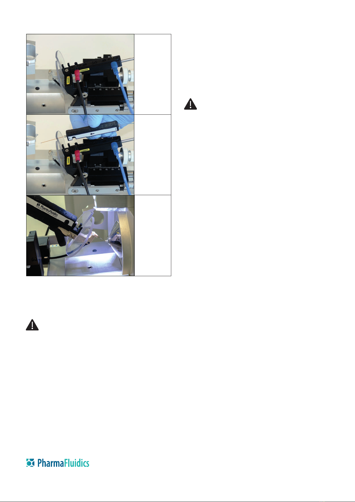
Figure 2. Installation of the µPAC™ Flex iON Connect on a ThermoFisher
Scientic Nanospray Flex™ ion source. Upper panel: mounting the docking
unit; middle panel: mounting the spray unit; lower panel: adjusting the
position of the emitter.
The µPAC™ Flex iON Connect MS interface is designed to be used in the nanoLC ow
range of 50 to 1,000 nL/min, with a maximum ow rate of approximately 1,500
nL/min. Selecting the appropriately-dimensioned emitter tip opening is crucial in
obtaining optimal spray quality for your specic application. In general, analyses at
a higher nanoLC ow rate (500-1500 nL/min) will benet from emitters with larger
tip openings (20-30 µm). Emitter tip openings ≤ 10 µm will give the best results for
analyses in the lower nanoLC ow range (50-500 nL/min). Although smaller tip
openings generate an optimal spray for reduced sample volumes, the risk of
blockage increases and, subsequently, more frequent exchange of the emitter is
inevitable.
www.pharmafluidics.com
Technologiepark-Zwijnaarde 82
B-9052 Ghent (Zwijnaarde)
Belgium
For research use only
Mounting the docking unit Mounting the spray unit Adjusting emitter tip posotion
CAUTION Avoid contact with high voltage. Before installing the µPAC™
Flex iON Connect interface, ensure that the mass spectrometer is in
stand-by and fully retract the DirectJunction™ adaptor to the end of
the sliding rails on the source. Then disconnect the HV cable from the
bottom of the NanoSpray Flex™ source.
Mobile phase
•
•
µPAC™ Flex iON Connect routine operation
•
•
•
Disconnecting the µPAC™ Flex iON Connect
•
•
Part numbers for spares and consumables
PharmaFluidics grounding cable ACC-groundcable
PharmaFluidics µPAC™ Flex iON Connect EMI-exion
VICI one-piece PEEK tting for 360 µm O.D. tubing C360NFPKG
VICI one-piece PEEK tting plug C360PPK
VICI ZDV union end plug ZU.5FPK
ESI emitter consumables
Fossil Ion Tech 360 O.D. x20 µm I.D. x5 cm FIT-20-5
Fossil Ion Tech 360 O.D. x10 µm I.D. x5 cm FIT-10-5
New Objective PicoTip emitter 10 µm tip, 5cm FS360-20-10-N-20
New Objective PicoTip emitter 15 µm tip, 5cm FS360-50-15-N-20
Further information
For column specications, pressure limits, pH range, tips and tricks including
operational instructions, visit:
https://www.pharmafluidics.com/products/
For technical support visit:
https://www.pharmafluidics.com/contact/
Turn o the spray voltage on the mass spectrometer.
Stop the HPLC ow and wait until the backpressure of the µPAC™ column has
decreased and stabilised.
Once the upper pressure limit of the HPLC has been adjusted to a maximum
of 350 bar, start the ow through the µPAC™ column and µPAC™ iON Flex
Connect.
Once the back pressure stabilises, apply the ow rate used to analyse
samples, e.g., 300 nL/min.
When the pressure has again stabilised, apply 1.5 kV to the emitter and wait
until the spray stabilises. If the spray does not stabilise, gradually increase
the voltage.
Only use ltered and degassed LCMS-grade mobile phases.
To prevent crystallisation and/or precipitation of solutes, alternate between
miscible mobile phases, e.g., acetonitrile (ACN), methanol (MeOH),
isopropanol (IPA), triuoroacetic acid (TFA), formic acid (FA).
CAUTION Avoid personal injury. Before removing an emitter, ensure
that the LCMS system is fully depressurised and disconnect the HV
cable from the bottom of the source. Else, the emitter may eject at
high speed and cause personal injury to you or someone in the near
vicinity.


