PHARO Funpool 23000 Series User manual

Pharo® FunPool
Pharo® Whirlpool
Funpool® 170x70 23000xxx
Funpool® 170x75 23010xxx
Funpool® 180x80 23020xxx
Funpool® 190x90 23030xxx
Funpool® 210x90 23040xxx
Funpool®140x140 23050xxx
Poolmaster Basic
Montageanleitung
Installation Instructions
Istruzioni di montaggio
Instructions de montage
Instrucciones de montaje
Montagehandleiding

Deutsch
INHALTSVERZEICHNIS
Vorwort 3
Sicherheitshinweise 5
In der Anleitung
verwendete Symbole 7
Technische Daten 8
170x70 / Maße / Technische Daten 12
170x75 / Maße / Technische Daten 14
180x80 / Maße / Technische Details 16
190x90 / Maße / Technische Details 18
140 x 140 / Maße /
Technische Daten 20
210 x 90/ Maße / Technische Daten 22
Ausstattung 24
Verpackungsinhalt 25
Benötigte Werkzeuge 27
Montagebeispiele 28
Whirlpoolmontage mit Schürze 30
Stromversorgung 34
Bedienelement Basic Poolmaster 36
Allgemeines / Pflegeanleitung Wanne
38
Störungen und Abhilfe 39
Service 42
Service Teile 44
Typenschilderklärung/
Konformitätserklärung 46
English
CONTENTS
Preface 3
Safety Precautions 5
Symbols Used in the Instructions 7
Technical Data 9
170x70 / Dimensions /
Technical Data 12
170x75 / Dimensions /
Technical Data 14
180x80 / Dimensions /
Technical Data 16
190x90 / Dimensions /
Technical Data 18
140 x 140 / Dimensions /
Technical Data 20
210 x 90 / Dimensions /
Technical Data 22
Equipment 24
Packaging Contents 25
Required Tools 27
Installation example 28
Whirlpool installation with skirt 30
Power SUpply 34
Basic Poolmaster operation 36
Generally / Care instruction for tub 38
Trouble shooting 40
Service 42
Spare Parts 44
Explanation of nameplate /
declaration of conformity 46
Italiano
Introduzione 3
Prescrizioni di sicurezza 5
Simboli utilizzati nel manuale 7
dati Tecnici 10
170x70 / Dimensioni /dati tecnici 12
170x75 / Dimensioni /dati tecnici 14
180x80 / Dimensioni /dati tecnici 16
190x90 / Dimensioni /dati tecnici 18
140 x 140 / Dimensioni /dati tecnici 20
210 x 90 / Dimensioni /dati tecnici 22
Equipaggiamento 24
Accessori coontenuti 25
Attrezzi necessari 27
Esempio di montaggio 28
Funzionalità del Basic Poolmaster 36
Generale/ precauzioni per
l’installazione della vasca 38
Risoluzione dei Problemi 41
Manutenzione 42
Parti Di Ricambio 44
Spiegazione targhetta/
dichiarazione di conformità 46
INDICE

Deutsch
Deutsch
VORWORT
Information
Die Montageanleitung enthält die wichtigsten
Montageschritte und Installationshinweise.
Sie vermeiden Montagefehler wenn Sie die
Montageanleitung aufmerksam durchlesen.
Unsachgemäße Montage kann zu Verletzungen
führen!
Die verwendeten Abbildungen sind
Prinzipdarstellungen. Das Aussehen Ihres
Whirlpools kann von diesen Abbildungen
abweichen.
In der Montageanleitung wird der Einbau mit
der optional erhältlichen Wannenschürze für
Whirlpools der Serie Funpool beschrieben.
Dementsprechend entfallen Montageschritte
bei einem Whirlpool ohne Schürzen.
Die Montageanleitung an einem sicheren
Ort aufbewahren. Und an nachfolgende
Eigentümer/Nutzer weitergeben.
Normen und Richtlinien
Die Anwendung desWhirlpools ist durch
folgende Richtlinien gewährleistet:
Niederspannungsrichtlinie 2006/95/EWG
Richtlinie 89/336/EWG
EN61000-6-3
EN61000-3-3
DIN VDE 100 Teil 701: 2002
EN 60335-2-60-2003
EN 14516
EN 12764
EN 198
Stromversorgung:
Die gesamte Stromversorgung erfolgt
über:
- Wechselstromanschluss mit 230V/N/
PE/50Hz.
- Hauptschalter zur Netztrennung mit
3 mm Kontaktöffnung.
Die Stromversorgung muss eine
Fehlerstrom-Schutzeinrichtung (RCD)
besitzen,der Bemessungsdifferenzstrom
ist von ≤ 30 mA abgesichert.
Elektro- Installation
Bei der Elektro-Installation sind die
entsprechenden VDE-, Landes- und
EVU-Vorschriften, in der jeweils gültigen
Fassung, einzuhalten.
Die Installations- und Prüfungsarbeiten
sind von einem zugelassenen
Elektrofachmann auszuführen.
Arbeiten am Whirlpool dürfen nur im
spannungsfreienZustandvorgenommen
werden!
Wasserablauf und Wasserzulauf
Anschluss für Wasserablauf und
Wasserzulauf sind nach den derzeitig
gültigen DIN 1988/EN1717
DIN1986/EN12056
und den örtlichen Vorschriften
durchzuführen.
English
English
PREFACE
Information
These installation instructions contain the
most important installing procedures and
installation notes.
Please read these instructions carefully in order
to avoid incorrect installation. Any improper
installation may lead to injuries!
The used illustrations are schematic
diagrams.
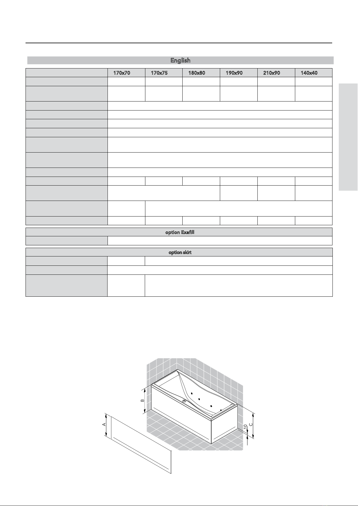
The following installation instructions will
describe the mounting of whirlpools with tub
skirt for whirlpools of 200 series. According to
this, mounting steps wouldn’t be done if these
tub skirt wouldn’t be installed.
Keep the installation / operating instructions
in a safe place and pass on to subsequent
owners/users.
Standards and Directives
The use of the whirlpool is safeguarded
by the following Directives:
Low Voltage Directive 2006/95/EEC
Directive 89/336/EEC
EN61000-6-3
EN61000-3-3
DIN VDE 100 Teil 701: 2002
EN 60335-2-60-2003
EN 14516
EN 12764
EN 198
Power supply:
Thecompletepowersupplyisperformed
by means of:
- A.C. connection with 230V/N/PE/
50Hz.
- Circuit breaker for disconnection
from power supply with 3 mm
contact opening.
The power supply must have a residual
current device (RCD) which must provide
protection with a rated residual current
of ≤ 30 mA fuse.
Electrical installation
For electrical installation, all applicable
VDE, country-specific and EVU
regulations in their respectively
valid versions must be observed. All
installation and inspection works must
be carried out by an approved electrician
and in accordance with VDE 0100 Part
701. All works at the whirlpool may only
be carried out in a de-energized state!
Water inlet / Water drain
Connections for water inlet and drain
have to be installed according to the
currently valid DIN 1988/EN1717 /
DIN1986/EN12056 as well as local
regulations.
Italiano
Italiano
INTRODUZIONE
Informazione
Le istruzioni di montaggio descrivono le
più importanti operazioni di montaggio e
le avvertenze di installazione per i prodotti
indicati nella pagina di copertina. Leggere
attentamente le istruzioni di montaggio per
evitare errori.
Il montaggio scorretto può provocare lesioni!
Le illustrazioni d’uso sono schematizzate con
diagrammi.
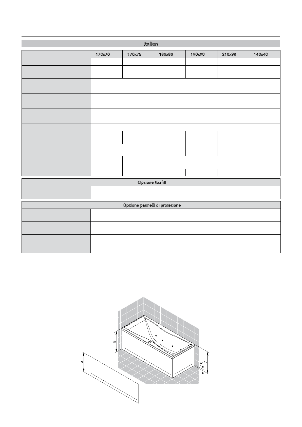
Le seguenti istruzioni di montaggio
descriveranno il montaggio delle vasche con
i pannelli Funpool. Per questo motivo, le fasi
di montaggio descritte vanno tralasciate se la
vasca non va installata con i pannelli.
Riporre le istruzioni di montaggio e d‘uso in
un luogo sicuro. Consegnarle ai proprietari/
utenti futuri.
Norme e direttive
L’uso della vasca idromassaggio è
garantito dalle seguenti direttive:
direttiva sulla bassa tensione 2006/95/CEE
direttiva 89/336/CEE
EN61000-6-3
EN61000-3-3
DIN VDE 100 Teil 701: 2002
EN 60335-2-60-2003
EN 14516
EN 12764
EN 198
Alimentazione elettrica:
L’intero sistema elettrico viene
alimentato:
- a tensione alternata a 230V/N/PE/
50Hz.
- con interruttore bipolare, con
apertura dei contatti di almeno 3
mm.
Il sistema elettrico deve possedere
un Interruttore magnetotermico
differenziale nominale ≤ 30 mA
Installazione elettrica
Per l'impianto elettrico si devono
rispettare le norme CEI e dell'azienda
elettrica vigenti.
I lavori di installazione e di collaudo
devono essere svolti da un tecnico
autorizzato. Qualsiasi intervento sulla
vasca va eseguito solo dopo aver
staccato la tensione elettrica!
Ingresso acqua/ scarico acqua
I collegamenti per acqua di mandata
e per l‘acqua di uscita devono essere
installati secondo le attuali norme DIN
1988/EN1717 / DIN1986/EN12056 ed
in conformità con le vigenti normative
locali.

Deutsch
VORWORT
Vor dem Einbau bitte prüfen:
Türbreite, im für die Installation
vorgesehenen Raum, beachten.
EinbaudesProduktes,inVerbindungmit
optionalenSchürzen,infertiggefliestes
Bad (Boden und Wände gefliest).
Boden/ - ablauf
Die Tragfähigkeit des Fußbodens
muss einer Belastung von 300 kg/m²
entsprechen.
Der Fußboden muss ausreichend
nivelliert sein, d.h. der Fußboden ist
waagerecht und eben.
Der Whirlpool muss auf einem,
für Feuchträume geeigneten
Boden montiert werden. Durch die
WhirlfunktiongelangtSpritzwasseraus
der Wanne!
Wasser/ Abwasser
Aufgrund des Wannenträgersystems
muss der Ablauf im Bodenbereich
vorgesehen werden. Ein
abwasserseitiger Anschluss aus der
Wand ist nicht möglich!
NachDINEN12764musseinegeeignete
SicherungseinrichtunggegenRückfluss
bauseits installiert werden. Dies
muss mindestens, nach EN 1717 eine
SicherungskombinationHDodernach
DIN 1988 ein Rohrunterbrecher A1 in
derjeweilsrichtigenMontagehöhesein.
Vor dem anschließen der
Wasserzuleitungenmüssendiesenach
DINfachgerechtdurchgespültwerden.
Elektro
elektrischer Anschluss: Kabel 3 x 1,5
mm² / Kabellänge 3500 mm
Potentialausgleich (Erdung): Kabel 4
mm² / Kabellänge 3500 mm
•
•
•
•
•
•
•
•
•
•
English
PREFACE
Please assure before installation:
Observe door width in the room
where the whirlpool is to be
installed.
Installation of product, in
combination with optional skirting,
in a tiled bathroom (floor and walls
tiled).
Floor/ floor drain
The floor's carrying capacity must
correspond to a load of 300 kg/m².
The floor must be sufficiently leveled,
i.e. it must be horizontal and even.
The whirlpool must be installed to
a sealed floor for damp locations.
Water can be splashed to the wall
and to the floor!
Water/ waste water
Please pay attention to the position of
thetubfeetandinstallationareawhen
installingthewaterandwastesupplies!
The waste pipe must be positioned at
floor level.Generally you cannot have
the waste pipe coming out from the
wall due to the Whirlpool Frame!
AccordingtoDINEN12764,asuitable
safetydevicepreventingbackflowhasto
beinstalledbythecustomer.According
toEN1717thismustatleastconsistofa
HDsafetycombinationoraccordingto
DIN1988ofapipeinterrupterA1atthe
respectivelycorrectinstallationheight.
Flushthewatersupplycircuitsaccording
to local regulations before installing.
Electric powered
electricalconnection:cable3x1.5mm²
/ cable length 3500 mm
Earthing cable: cable 4 mm² / cable
length 3500 mm
•
•
•
•
•
•
•
•
•
•
Italiano
INTRODUZIONE
Da controllare prima del montaggio:
Fare attenzione all’apertura della
porta nel bagno dove verrà installata
la vasca.
Il montaggio del prodotto, con
pannelli di protezione disponibili
come optional, deve essere fatto in
un bagno già piastrellato (pavimento
e parete).
Pavimento/ scarico a pavimento
Laportataminimadelpavimentodeve
essere di 300 kg/m².
Il pavimento deve essere livellato e
sufficientemente piano.
La vasca deve essere installata su
un pavimento resistente all’umidità.
L’acquapuòesserespruzzatasulmuro
and sul pavimento!
Acqua/ acqua di scarico
Lo scarico deve essere posizionato al
livello del pavimento. Generalmente
non potete far uscire il tubo di scarico
dalmuroacausadeltelaiodellavasca!
Fareattenzioneallaposizionedeipiedini
della vasca e all‘area di installazione,
quandoinstallategliallacciamentiidrici
e lo scarico!
Secondo la DIN EN 12764, in sede
di montaggio deve essere installato
un dispositivo di sicurezza idoneo
contro il riflusso. Secondo la EN 1717,
questo dispositivo deve essere una
combinazione di sicurezza HD o,
secondolaDIN1988,undisconnettore
A1 all‘altezza di montaggio corretta.
Il riempimento tramite il circuito
idraulico deve esse in conformità alle
vigenti normative locali.
Elettrico
Connessioneelettrica:cavo3x1,5mm
/ lunghezza 3500 mm
connessione terra: cavo 4 mm /
lunghezza 3500 mm
•
•
•
•
•
•
•
•
•
•
•

Deutsch
Deutsch
Hinweise zur Verwendung
InihrerBewegungeingeschränkteältere
und behinderte Personen sollten bei
derNutzungdesWhirlpoolsbesondere
Sorgfalt walten lassen.
DieBadewassertemperaturdarf40°C
nicht übersteigen.
KeineÜberschreitungderBadezeitvon
20MinutenbeieinerWassertemperatur
von >= 38°C.
Falls Sie gesundheitliche Bedenken
haben,setzenSiesichmitIhremArztin
Verbindung.
NachjedemBadmussderPoolentleert
werden.
Beispiele zur Nichtverwendung
Die Whirlpools dürfen nicht im
öffentlichenBereicheingesetztwerden.
Die Whirlpools dürfen nicht im
Außenbereich installiert werden.
Kinderdürfennichtunbeaufsichtigtden
Whirlpool benutzen.
z. B. Hunde, Katzen oder sonstige
HaustieredürfennichtimWhirlpoolder
Hygiene unterzogen werden.
•
•
•
•
•
•
•
•
•
SICHERHEITSHINWEISE
English
English
Tip for using
Elderly and handicapped persons
should exercise particular care when
using the whirlpool.
The water temperature should not
exceed 40 °C.
Donotexceed20minutesbathingtime
with a water temperature of >= 38°C.
Please contact your doctor if you have
health concerns.
The pool must be emptied after each
bath.
Examples for non-using
The whirlpools may not be used in
public areas.
The whirlpools may not be used
outdoors.
Childrenmustnotbeleftunattendedin
the Whirlpool.
e.g.dogs,catsorotheranimalsmustnot
be wash in the whirlpool.
•
•
•
•
•
•
•
•
•
•
SAFETY PRECAUTIONS
Italiano
Italiano
Esempi di uso
Lepersoneanzianeedisabilichehanno
difficoltà a muoversi devono prestare
particolareattenzionequandousanola
vasca idromassaggio.
La temperatura dell’acqua non
dovrebbe superare i 40°C.
Laduratadelbagnonondevesuperare
i 20 minuti con una temperatura
dell’acqua di >= 38°C.
Consultate il vostro medico se avete
qualche malattia.
La vasca deve essere svuotata dopo
ogni bagno.
Esempi di uso improprio
Lavascaidromassaggiononpuòessere
usata in luoghi pubblici.
Lavascaidromassaggiononpuòessere
usata all’aperto.
I bambini non devono essere lasciati
incustoditi nella vasca.
Per esempio icani,i gattio altri animali
non devono essere lavati nella vasca,
per questioni igeniche.
•
•
•
•
•
•
•
•
•
PRESCRIZIONI DI SICUREZZA

Deutsch
- Während Reinigungs- und
Wartungsarbeiten muss der Haupt
schalter auf "OFF" gestellt sein.
- Wartungs-undEinstellarbeitendürfen
nurvoneinemFachmanndurchgeführt
werden.
- Nach Wartungsarbeiten müssen
die Serviceabdeckungen ordnungs
gemäß montiert werden.
- Bestehende Sicherheitsvorkehr
ungen und Sicherheitseinrichtungen
dürfen nicht verändert oder entfernt
werden.
- Der Whirlpool darf in seiner Bauart
nicht verändert werden. Nur
Originalersatzteile verwenden.
- ElektrischeVerbraucher>12V(Radio,
Föhn, usw.) dürfen nicht in der Nähe
oderimWhirlpoolverwendetwerden!
Kein essigsäurehaltiges Silikon
verwenden.
Durch Gebrauch von essigsäurehaltigem
Silikon können Acryl- bzw. Metallteile des
Whirlpools beschädigt werden.
FürdasVerfugenzwischendenElementen
pilzhemmendesSanitärsilikonverwenden.
Dennoch kann es unter Umständen zu
Verfärbungen des Silikondichtstoffes
kommen.
Silikonfugen sind Wartungsfugen und
unterliegen nicht der Gewährleistung.
Die Wanne vor Inbetriebnahme oder Test
der Whirlfunktionen gründlich mit der
Handbrause ausspülen!
Dichtheitsprüfung und
InbetriebnahmeprüfunggemäßEN12764
durchführen
SICHERHEITSHINWEISE
English
- The main switch must be set to "OFF"
during cleaning and maintenance
works.
- Maintenance and adjustment works
must be carried out by experts only.
- Allservicecoversmustbeappropriately
re-installed after maintenance works.
- Anyinstalledsafetyprovisionsorsafety
equipment may not be modified or
removed.
- The whirlpool’s construction must not
bechanged.Onlyoriginalcomponents
may be used.
- Donotusehighervoltagethan12volts
(radio,hair-dryer,etc)inor close tothe
whirlpool!
Donotusesiliconecontainingaceticacid!
Acrylicormetalpartsofthewhirlpoolcanbe
damagedbytheuseofsiliconecontaining
acetic acid.
Fortheflexiblesealsbetweentheelements
we advise to use schimmelwerende
silicone kit. Despite this, and dependant
on circumstances,colorchanges in the kit
can happen. If cleaning does not bring
the wanted result, the seals have to be
exchanged. Renewing is not within our
warranty.
The tub must be cleaned thoroughly with
thehandshowerbeforusingortestingthe
whirlpool functions!
Perform leak test.
SAFETY PRECAUTIONS
Italiano
- Durante i lavori di pulizia e di
manutenzione,l'interruttoregenerale
deve essere su "OFF".
- Gli interventi di manutenzione e
regolazionedevonoesseresvolti solo
da un tecnico autorizzato.
- Al termine della manutenzione si
devono rimontare correttamente le
coperture di servizio.
- I dispositivi di sicurezza installati non
devonoesserenémodificatinérimossi.
- La costruzione della vasca non deve
essere cambiata. Devono essere
utilizzati solo componenti originali.
- Non utilizzare apparecchi elettrici
>12V(radio,asciugacapelli...etc)nelle
vicinanze o all‘interno della vasca!
Non utilizzare silicone contenente acido
acetico.
Utilizzando silicone contenente acido
aceticovièilpericolodidanneggiareparti
inmaterialeacrilicooppurepartimetalliche
della vasca.
Per la sigillatura tra gli elementi
raccomandiamol‘usodisiliconeantimuffa
per sanitari. Nonostante ciò, si possono
verificaremacchieocolorimentidelsilicone
sigillante.Nelcasoincuigliscolorimentio
macchienonsilascianoeliminarepulendo
semplicemente i giunti, è necessario
sostituirli. I giunti di silicone sono giunti
soggettiamanutenzioneenonfannoparte
della garanzia concessa.
Prima della messa in esercizio oppure
prima di eseguire la prova delle funzioni
dell‘impiantowhirlpool,lavascadeveessere
sciacquatameticolosamenteconladoccetta
a mano!
Verificare possibili perdite d’acquta.
PRESCRIZIONI DI SICUREZZA

Deutsch
Deutsch
In der vorliegenden Einbauanleitung und an
einigen Stellenauf dem Produkt selbstbefinden
sich Symbole, die hier unten beschrieben
werden.
ACHTUNG STROMSCHLAGGEFAHR
Meldet dem betreffenden Personal, dass der
beschriebeneVorgang,fallsnichtunterEinhaltung
derSicherheitsvorschriftenausgeführt,dasRisiko
eines elektrischen Schlags birgt.
ACHTUNG ALLGEMEINE GEFAHR
Meldet dem betreffenden Personal, dass der
beschriebeneVorgang,fallsnichtunterEinhaltung
derSicherheitsvorschriftenausgeführt,dasRisiko
von Körperverletzungen birgt.
ACHTUNG ZWEI PERSONEN NOTWENDIG
BezeichneteinebestimmteVorgehensweise.Wenn
diese nicht eingehalten wird kann das Produkt
oder etwas in seiner Umgebung beschädigt
werden. (Die Montage muss von zwei Personen
durchgeführt werden)!
HINWEIS
WeistdasbetreffendePersonalaufInformationen
hin, deren Inhalt wichtig ist und berücksichtigt
werden soll.
ELEKTRISCHER INSTALLATEUR
Fachtechniker,derimstandeist,dasProduktunter
normalen Bedingungen einzubauen. Er ist für
alle Eingriffe elektrischer Art wie Einstellungen,
Wartung und Reparaturen zuständig. Er ist
imstande,unterSpannunginSchaltschränkenoder
elektrischen Dosen zu arbeiten.
IN DER ANLEITUNG VERWENDETE SYMBOLE
English
English
The symbols described below appear in these
InstallationInstructionsandinsomelocationson
the product itself.
ATTENTION RISK OF ELECTRIC SHOCK
Informsthepersonnelconcernedthattheprocess
described,unlessperformedincompliancewith
the safety rules, bears the risk of electric shock.
ATTENTION GENERAL HAZARD
Informsthepersonnelconcernedthattheprocess
described,unlessperformedincompliancewith
the safety rules, bears the risk of injury.
ATTENTION: TWO PEOPLE REQUIRED!
Describesaspecificprocedure.Ifthisprocedure
is not observed, the product or objects within
its environment may be damaged. (The steam
shower's installation must be carried out by two
people)!
NOTE
Informsthepersonnelconcernedof information
with important contents to be observed.
ELECTRICIAN
Specialist technician capable of installing the
productundernormalconditions.Heisresponsible
forallelectricalwork,suchassetting,maintenance
andrepairs.Heiscapableofworkinginenergized
control cabinets or on electrical sockets.
SYMBOLS USED IN THE INSTRUCTIONS
Italiano
Italiano
Nel presente manuale di istruzioni di montaggio si
trovanodeisimbolialcunideiqualisitrovanoapplicati
in alcuni punti del prodotto stesso. In questa parte
delladocumentazionesiprocedealladescrizionedel
significato di questi simboli.
ATTENZIONE PERICOLO DI SCOSSA
ELETTRICA
Segnalaalpersonaleinteressatochel'operazione
descritta può comportare il rischio di una scossa
elettricase non eseguita nelpieno rispetto delle
norme di sicurezza.
ATTENZIONE PERICOLO GENERALE
Segnalaalpersonaleinteressatochel'operazione
descrittapuòcomportareilrischiodiseriincidenti
senoneseguitanelpienorispettodellenormedi
sicurezza.
ATTENZIONE: SONO NECESSARIE DUE
PERSONE!
Indicaundeterminatoprocedimento.Senonviene
rispettato,ilprodottoooggettinellesuevicinanze
possonoessere danneggiati(ilmontaggio della
doccia a vapore deve essere eseguito da due
persone)!
NOTA BENE
Segnalaalpersonaleinteressatoinformazionicon
uncontenutoimportantechedeveesseretenuto
in considerazione.
INSTALLATORE ELETTRICO
Tecnicospecializzatoingradodiinstallareilprodotto
innormalicondizionidilavoro.Tralesuecompetenze
rientrano tutti gli interventi di tipo elettrico come
registrazioni,manutenzioneeriparazioni.Eglièingrado
diintervenireinquadrielettriciadarmadiooppuresu
prese per la corrente che si trovino sotto tensione.
SIMBOLI UTILIZZATI NEL MANUALE

170x70 170x75 180x80 190x90 210x90 140x40
Form Rechteck Rechteck Rechteck Rechteck Sechseck Eck
Inhalt + 1 Person (70kg) in L 110 178 217 254 214 230
Material ABS 20%, PMMA 80%
Abwasseranschluss DN 50
elektr. Zuleitung 230V / 50Hz
Schutzart IPX 5
Leistung Hydropumpe Basic max.0,8 kW
Leistung Hydropumpe Combi max.0,85 kW
Förderleistung max. 380 L/min
Anzahl der Hydrodüsen 10 10 12 12 12 10
Verpackungsgröße L x B x H
in mm 1895x895x970 1970x1610
x980
1600x1600
x1010
1600x1600
x1010
(B) Einstellbare Höhe der
Wanne min/max in mm 575 - 630 635 - 690
Option Exafill
Wasseranschluss kalt/warm DN 20 3/4” Aussengewinde
Option Schürzen
(A) Schürzenhöhe in mm 545 605
Schürzenmontage auf gefliesten Boden und vor gefliester Wand
(C) Höhe der Wanne mit
Schürze inkl. 10mm Lüf-
tungsabstand in mm
605 660
TECHNISCHE DATEN
Deutsch

DeutschEnglish
English
170x70 170x75 180x80 190x90 210x90 140x40
Form oblong oblong oblong oblong hexagon corner
Tub capacity + 1 person
(70kg) 110 178 217 254 214 230
Material ABS 20%, PMMA 80%
Drain DN 50
Electrical supply 230V / 50Hz
Degree of prot. against water IPX 5
Connected load hydropump
basic max.0,8 kW
Connected load hydropump
combi max.0,85 kW
Max.delivery rate max. 380 L/min
Number of water nozzles 10 10 12 12 12 10
Packaging dim. L x B x H in
mm 1895x895x970 1970x1610
x980
1600x1600
x1010
1600x1600
x1010
(B) Height of tub variable
min/max in mm 575 - 630 635 - 690
option Exafill
Water connection hot/cold DN 20 3/4” external screw thread
option skirt
(A) Height of skirt in mm 545 605
Skirtmontage on tiled floor and against tiled wall
(C) Height of tub with skirt
incl. 10mm aering-distan-
ce in mm
605 660
TECHNICAL DATA
Italiano

10
Italian
DATI TECNICI
170x70 170x75 180x80 190x90 210x90 140x40
Forma rettangolo rettangolo rettangolo rettangolo esagono ad angolo
Capacità della vasca + 1 per-
sona (70kg) 110 178 217 254 214 230
Materiale ABS 20%, PMMA 80%
Scarico DN 50
Alimentazione elettrica 230V / 50Hz
Grado di protezione IPX 5
Potenza pompa idraulica Basic max.0,8 kW
Potenza pompa idraulica Combi max.0,85 kW
Portata max. 380 L/min
Numero bocchette
idromassaggio 10 10 12 12 12 10
Imballo dim. L x B x H in mm 1895x895x970 1970x1610
x980
1600x1600
x1010
1600x1600
x1010
(B) Altezza variabile della vas-
ca min/max in mm 575 - 630 635 - 690
Opzione Exafill
Connessione acqua
fredda/calda DN 20 3/4” filetto esterno della vite
Opzione pannelli di protezione
(A) Altezza del pannello ester-
no in mm 545 605
Montaggio pannelli di prote-
zione su pavimento piastrellato e davanti parete piastrellata
(C) Altezza della vasca con
pannello incluso 10 mm
di areazione.
605 660

11
DeutschEnglishItaliano

1
Deutsch
Legende:
Die Abb. ist ein Montagebeispiel, es
sind noch weitere Einbausituationen
möglich.
A 1,2... mögliche Serviceöffnungen für
Technik (Abmessung 500x500 mm)
X Empfohlener Bereich für den Kalt-
(rechts) und den Warmwasseranschluss
(links) DN 15.
Y Empfohlener Bereich für den
Wasserablauf DN 50 (Boden: Oberkante
Anschlussmuffe bündig Standfläche
Wannenfüße)
Z Anschluss der elektrischen Zuleitung
und des Potentialausgleichs (Erdung)*
im gesamten Bereich der Wand
möglich. Ausreichend Abstand zu den
Außenkanten einhalten!
Wannenfuß
Poolmaster Basic
Haltegriff
Pos.
Einbauposition mit Serviceöffnung und
Pumpe links
Pos.
Einbauposition mit Serviceöffnung und
Pumpe rechts
* Querschnitt von mindestens 4 mm
170X70 / MASSE / TECHNISCHE DATEN
English
Legend:
The picture is an installation example,
it‘s possible to install other situations.
A 1,2... possible service opening area for
maintenance (dimensions 500x500 mm)
X Recommended position for cold
water connection (right) and hot water
connection (left) DN 15.
Y Recommended position for the water
drainage Ø 50 (floor: upper rim of
connection pipe flush with tub feet
contact area).
Z The electrical supply and the earth cable
connection* are made out of the wall.
Keep an adequate distance to the outer
edges of the tub!
tub feet
Poolmaster Basic
grab bar
Pos.
Installation position with service
opening area and pump left
Pos.
Installation position with service
opening area and pump right
* Cross-section at least 4 mm
170X70 / DIMENSIONS / TECHNICAL DATA
Italiano
Legenda:
Il disegno è un esempio di installazione,
è possibile installare la vasca in altre
configurazioni.
A 1,2,3... possibili aree di ispezione tecnica
(dimensioni 500x500 mm)
X Posizione raccomandata per
connessione acqua fredda (destra)
e connessione acqua calda (sinistra)
DN15.
Y Posizione raccomandata per lo scarico
d’acqua Ø 50 (Pavimento: il bordo più
alto della connessione a livello dei
piedini della vasca)
Z La fornitura elettrica e cavo di
connessione terra(*) sono fatte fuori dal
muro. Tenere una adeguata distanza dai
bordi della vasca!
piedini vasca
Poolmaster Basic
Maniglia
Pos.
area di ispezione e pompa con
posizione sinistra
Pos.
area di ispezione e pompa con
posizione destra
* sezione minima 4 mm
170X70 / DIMENSIONI /DATI TECNICI

1
1 2
Pos. Pos.
X
Y
Z
X
Y
Z
DeutschEnglishItaliano

1
Deutsch
Legende:
Die Abb. ist ein Montagebeispiel, es
sind noch weitere Einbausituationen
möglich.
A 1,2... mögliche Serviceöffnungen für
Technik (Abmessung 500x500 mm)
X Empfohlener Bereich für den Kalt-
(rechts) und den Warmwasseranschluss
(links) DN 15.
Y Empfohlener Bereich für den
Wasserablauf DN 50 (Boden: Oberkante
Anschlussmuffe bündig Standfläche
Wannenfüße)
Z Anschluss der elektrischen Zuleitung
und des Potentialausgleichs (Erdung)*
im gesamten Bereich der Wand
möglich. Ausreichend Abstand zu den
Außenkanten einhalten!
Wannenfuß
Poolmaster Basic
Haltegriff
Pos.
Einbauposition mit Serviceöffnung und
Pumpe links
Pos.
Einbauposition mit Serviceöffnung und
Pumpe rechts
* Querschnitt von mindestens 4 mm
170X75 / MASSE / TECHNISCHE DATEN
English
Legend:
The picture is an installation example,
it‘s possible to install other situations.
A 1,2... possible service opening area for
maintenance (dimensions 500x500 mm)
X Recommended position for cold
water connection (right) and hot water
connection (left) DN 15.
Y Recommended position for the water
drainage Ø 50 (floor: upper rim of
connection pipe flush with tub feet
contact area).
Z The electrical supply and the earth cable
connection* are made out of the wall.
Keep an adequate distance to the outer
edges of the tub!
tub feet
Poolmaster Basic
grab bar
Pos.
Installation position with service
opening area and pump left
Pos.
Installation position with service
opening area and pump right
* Cross-section at least 4 mm
170X75 / DIMENSIONS / TECHNICAL DATA
Italiano
Legenda:
Il disegno è un esempio di installazione,
è possibile installare la vasca in altre
configurazioni.
A 1,2,3... possibili aree di ispezione tecnica
(dimensioni 500x500 mm)
X Posizione raccomandata per
connessione acqua fredda (destra)
e connessione acqua calda (sinistra)
DN15.
Y Posizione raccomandata per lo scarico
d’acqua Ø 50 (Pavimento: il bordo più
alto della connessione a livello dei
piedini della vasca)
Z La fornitura elettrica e cavo di
connessione terra(*) sono fatte fuori dal
muro. Tenere una adeguata distanza dai
bordi della vasca!
piedini vasca
Poolmaster Basic
Maniglia
Pos.
area di ispezione e pompa con
posizione sinistra
Pos.
area di ispezione e pompa con
posizione destra
* sezione minima 4 mm
170X75 / DIMENSIONI /DATI TECNICI

1
1 2
Pos. Pos.
X
Y
Z
X
Y
Z
DeutschEnglishItaliano

1
Deutsch
Legende:
Die Abb. ist ein Montagebeispiel, es
sind noch weitere Einbausituationen
möglich.
A 1,2... mögliche Serviceöffnungen für
Technik (Abmessung 500x500 mm)
X Empfohlener Bereich für den Kalt-
(rechts) und den Warmwasseranschluss
(links) DN 15.
Y Empfohlener Bereich für den
Wasserablauf DN 50 (Boden: Oberkante
Anschlussmuffe bündig Standfläche
Wannenfüße)
Z Anschluss der elektrischen Zuleitung
und des Potentialausgleichs (Erdung)*
im gesamten Bereich der Wand
möglich. Ausreichend Abstand zu den
Außenkanten einhalten!
Wannenfuß
Poolmaster Basic
Haltegriff
Pos.
Einbauposition mit Serviceöffnung und
Pumpe links
Pos.
Einbauposition mit Serviceöffnung und
Pumpe rechts
* Querschnitt von mindestens 4 mm
180X80 / MASSE / TECHNISCHE DETAILS
English
Legend:
The picture is an installation example,
it‘s possible to install other situations.
A 1,2... possible service opening area for
maintenance (dimensions 500x500 mm)
X Recommended position for cold
water connection (right) and hot water
connection (left) DN 15.
Y Recommended position for the water
drainage Ø 50 (floor: upper rim of
connection pipe flush with tub feet
contact area).
Z The electrical supply and the earth cable
connection* are made out of the wall.
Keep an adequate distance to the outer
edges of the tub!
tub feet
Poolmaster Basic
grab bar
Pos.
Installation position with service
opening area and pump left
Pos.
Installation position with service
opening area and pump right
* Cross-section at least 4 mm
180X80 / DIMENSIONS / TECHNICAL DATA
Italiano
Legenda:
Il disegno è un esempio di installazione,
è possibile installare la vasca in altre
configurazioni.
A 1,2,3... possibili aree di ispezione tecnica
(dimensioni 500x500 mm)
X Posizione raccomandata per
connessione acqua fredda (destra)
e connessione acqua calda (sinistra)
DN15.
Y Posizione raccomandata per lo scarico
d’acqua Ø 50 (Pavimento: il bordo più
alto della connessione a livello dei
piedini della vasca)
Z La fornitura elettrica e cavo di
connessione terra(*) sono fatte fuori dal
muro. Tenere una adeguata distanza dai
bordi della vasca!
piedini vasca
Poolmaster Basic
Maniglia
Pos.
area di ispezione e pompa con
posizione sinistra
Pos.
area di ispezione e pompa con
posizione destra
* sezione minima 4 mm
180X80 / DIMENSIONI /DATI TECNICI

1
1 2
Pos. Pos.
X
Y
Z
X
Y
Z
DeutschEnglishItaliano

1
Deutsch
Legende:
Die Abb. ist ein Montagebeispiel, es
sind noch weitere Einbausituationen
möglich.
A 1,2... mögliche Serviceöffnungen für
Technik (Abmessung 500x500 mm)
X Empfohlener Bereich für den Kalt-
(rechts) und den Warmwasseranschluss
(links) DN 15.
Y Empfohlener Bereich für den
Wasserablauf DN 50 (Boden: Oberkante
Anschlussmuffe bündig Standfläche
Wannenfüße)
Z Anschluss der elektrischen Zuleitung
und des Potentialausgleichs (Erdung)*
im gesamten Bereich der Wand
möglich. Ausreichend Abstand zu den
Außenkanten einhalten!
Wannenfuß
Poolmaster Basic
Haltegriff
Pos.
Einbauposition mit Serviceöffnung und
Pumpe links
Pos.
Einbauposition mit Serviceöffnung und
Pumpe rechts
* Querschnitt von mindestens 4 mm
190X90 / MASSE / TECHNISCHE DETAILS
English
Legend:
The picture is an installation example,
it‘s possible to install other situations.
A 1,2... possible service opening area for
maintenance (dimensions 500x500 mm)
X Recommended position for cold
water connection (right) and hot water
connection (left) DN 15.
Y Recommended position for the water
drainage Ø 50 (floor: upper rim of
connection pipe flush with tub feet
contact area).
Z The electrical supply and the earth cable
connection* are made out of the wall.
Keep an adequate distance to the outer
edges of the tub!
tub feet
Poolmaster Basic
grab bar
Pos.
Installation position with service
opening area and pump left
Pos.
Installation position with service
opening area and pump right
* Cross-section at least 4 mm
190X90 / DIMENSIONS / TECHNICAL DATA
Italiano
Legenda:
Il disegno è un esempio di installazione,
è possibile installare la vasca in altre
configurazioni.
A 1,2,3... possibili aree di ispezione tecnica
(dimensioni 500x500 mm)
X Posizione raccomandata per
connessione acqua fredda (destra)
e connessione acqua calda (sinistra)
DN15.
Y Posizione raccomandata per lo scarico
d’acqua Ø 50 (Pavimento: il bordo più
alto della connessione a livello dei
piedini della vasca)
Z La fornitura elettrica e cavo di
connessione terra(*) sono fatte fuori dal
muro. Tenere una adeguata distanza dai
bordi della vasca!
piedini vasca
Poolmaster Basic
Maniglia
Pos.
area di ispezione e pompa con
posizione sinistra
Pos.
area di ispezione e pompa con
posizione destra
* sezione minima 4 mm
190X90 / DIMENSIONI /DATI TECNICI

1
1 2
Pos. Pos.
X
Y
Z
X
Y
Z
DeutschEnglishItaliano

0
Deutsch
Legende:
Die Abb. ist ein Montagebeispiel, es
sind noch weitere Einbausituationen
möglich.
A 1,2... mögliche Serviceöffnungen für
Technik (Abmessung 500x500 mm)
X Empfohlener Bereich für den Kalt-
(rechts) und den Warmwasseranschluss
(links) DN 15.
Y Empfohlener Bereich für den
Wasserablauf DN 50 (Boden: Oberkante
Anschlussmuffe bündig Standfläche
Wannenfüße)
Z Anschluss der elektrischen Zuleitung
und des Potentialausgleichs (Erdung)*
im gesamten Bereich der Wand
möglich. Ausreichend Abstand zu den
Außenkanten einhalten!
Wannenfuß
Poolmaster Basic
Haltegriff
Pos.
Einbauposition mit Serviceöffnung und
Pumpe links
Pos.
Einbauposition mit Serviceöffnung und
Pumpe rechts
* Querschnitt von mindestens 4 mm
140 X 140 / MASSE / TECHNISCHE DATEN
English
Legend:
The picture is an installation example,
it‘s possible to install other situations.
A 1,2... possible service opening area for
maintenance (dimensions 500x500 mm)
X Recommended position for cold
water connection (right) and hot water
connection (left) DN 15.
Y Recommended position for the water
drainage Ø 50 (floor: upper rim of
connection pipe flush with tub feet
contact area).
Z The electrical supply and the earth cable
connection* are made out of the wall.
Keep an adequate distance to the outer
edges of the tub!
tub feet
Poolmaster Basic
grab bar
Pos.
Installation position with service
opening area and pump left
Pos.
Installation position with service
opening area and pump right
* Cross-section at least 4 mm
140 X 140 / DIMENSIONS / TECHNICAL DATA
Italiano
Legenda:
Il disegno è un esempio di installazione,
è possibile installare la vasca in altre
configurazioni.
A 1,2,3... possibili aree di ispezione tecnica
(dimensioni 500x500 mm)
X Posizione raccomandata per
connessione acqua fredda (destra)
e connessione acqua calda (sinistra)
DN15.
Y Posizione raccomandata per lo scarico
d’acqua Ø 50 (Pavimento: il bordo più
alto della connessione a livello dei
piedini della vasca)
Z La fornitura elettrica e cavo di
connessione terra(*) sono fatte fuori dal
muro. Tenere una adeguata distanza dai
bordi della vasca!
piedini vasca
Poolmaster Basic
Maniglia
Pos.
area di ispezione e pompa con
posizione sinistra
Pos.
area di ispezione e pompa con
posizione destra
* sezione minima 4 mm
140 X 140 / DIMENSIONI /DATI TECNICI
This manual suits for next models
5
Table of contents
Other PHARO Bathtub manuals
Popular Bathtub manuals by other brands

Ariel
Ariel ARIEL HW 123 user manual

Crosswater
Crosswater Nuvola US-N22CS installation instructions

Novellini
Novellini DIVINA DUAL Instructions for installation, use and maintenance manual

Master equipment
Master equipment Superior TP382 Assembly instructions

glass 1989
glass 1989 astor 160/70 manual

Kohler
Kohler K-1394 Series Roughing-In Guide

Kohler
Kohler Archer K-1125-RA Roughing-In Guide

Ella
Ella OW5335S Installation & owner's manual

Whitehall
Whitehall P-10-S INSTRUCTIONS FOR OPERATION AND CARE OF

EAGO
EAGO AM154ETL-R5 Installation instruction

American Standard
American Standard Whirlpool/Bathing Pool 2748.XXXW installation instructions

TEIKO
TEIKO EXCELLENT DUO user manual