Phase LHX Series User manual


ii | P a g e
SAFETY MESSAGES AND WARNINGS
To ensure safe and reliable operation of Phase Technologies variable frequency drives, it is important
to carefully read and understand this manual and to read and observe all warning labels attached to
the drive before installing the equipment. Please follow all instructions exactly and always keep this
manual with the equipment for quick and easy reference.
Definitions of Warning Signs and Symbols
CAUTION: Indicates a potentially hazardous situation that could result in injury or damage to the
product.
WARNING: Indicates a potentially hazardous situation that could result in serious injury or death.
HIGH VOLTAGE: Indicates high voltage. The voltage associated with the procedures or operations
referenced could result in serious injury or death. Use caution and follow instructions carefully.
READ THESE WARNINGS BEFORE INSTALLING OR
OPERATING EQUIPMENT!
WARNING: Risk of electric shock. De-energize the unit by disconnecting all incoming sources of
power, then wait for the time specified on the drive warning label, before servicing the equipment.
HIGH VOLTAGE: This equipment is connected to line voltages that can create a potentially
hazardous situation. Electric shock could result in serious injury or death. This device should be
installed only by trained, licensed, and qualified personnel. Follow instructions carefully and observe
all warnings.
WARNING: This equipment should be installed and serviced by qualified personnel familiar with the
type of equipment and experienced in working with dangerous voltages.
WARNING: Installation of this equipment must comply with the National Electrical Code (NEC) and
all applicable local codes. Failure to observe and comply with these codes could result in risk of
electric shock, fire, or damage to the equipment.
CAUTION: The AUX1 through AUX4 terminals are galvanically isolated, with approximately 5V
potential between them. DO NOT apply voltage to the terminals. Use dry contacts only.
CAUTION: Circuit breakers or fuses, proper ground circuits, disconnect and other safety equipment
and their proper installation are not provided by Phase Technologies, LLC, and are the responsibility
of the end user.

iii | P a g e
CAUTION: Long leads between the unit and the motor with an unfiltered PWM voltage can lead
to dangerous voltage rise from reflected harmonics. Very long leads, such as in deep well
submersible pump applications, may require the use of a sine wave filter to remove most of the
harmonics from the waveform. Consult the factory or a knowledgeable source on motor
protection filters if your motor is more than 50 feet from the drive.
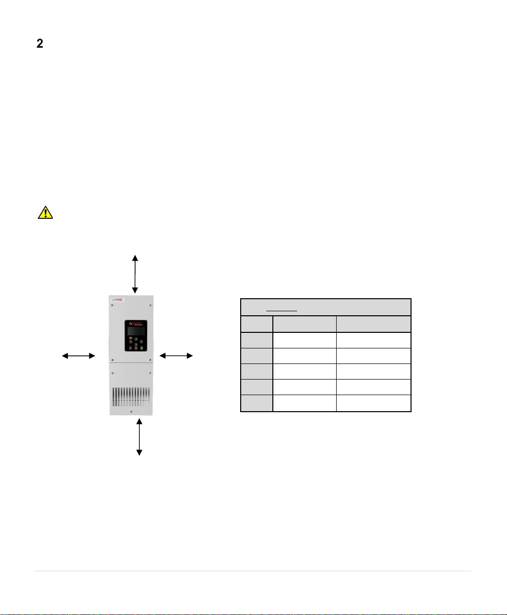
CAUTION: Failure to maintain adequate clearance for free flow of cooling air may lead to
overheating of the unit and cause damage or fire.
WARNING: Suitable for use in a circuit capable of delivering not more than 65 kA RMS
symmetrical amperes, 460 VAC.
WARNING: Wire used within the motor circuit and all field wiring terminals must be rated at least
60 °C.
WARNING: Use wire size suitable for Class 1 circuits.
WARNING: Input power connections should be made by a qualified electrician into a nominal
460V circuit for models with 460V input, with adequate current carrying capacity. Branch circuit
protection to the drive should be provided by appropriate size fuses or circuit breaker. Circuit
breaker and fuse ratings for each model are listed in Table 2, Table 3, and Table 4.
WARNING: These devices are equipped with integral solid-state short circuit protection. Integral
solid-state short circuit protection does not provide branch circuit protection. Branch circuit
protection must be provided in accordance with the National Electrical Code and any additional
local codes.
CAUTION: Use 600 V vinyl-sheathed wire or equivalent. The voltage drop of the leads needs to
be considered in determining wire size. Voltage drop is dependent on wire length and gauge.
Use copper conductors only.
CAUTION: Wires fastened to the terminal blocks shall be secured by tightening the terminal
screws to a torque value listed in Table 2, Table 3, and Table 4.
CAUTION: The maximum wire gauge for the input and output terminals are listed in Table 2,
Table 3, and Table 4.
CAUTION: Never allow bare wire to contact the metal surfaces.
CAUTION: Never connect AC main power to the output terminals U, V, and W.

iv | P a g e
WARNING: Under certain conditions, the motor may automatically restart after a fault has
stopped it. Make sure power to the drive has been disconnected before approaching or servicing
the equipment. Otherwise, serious injury may occur.
CAUTION: Use caution when applying power to the main input terminals of the unit. If the drive
is programmed to allow automatic restarts, the drive will initialize in AUTO mode and the motor
load may start as soon as the drive is energized.
CAUTION: The AC motor load must be connected directly to the output terminals of the drive.
Do not install relays, disconnect switches, or wire nuts between the drive and the motor load.
CAUTION: Before the motor is connected to the output terminals, check all output lines for line-
to-ground faults using a megger. There is a direct path through the drive circuitry for ground fault
currents that can be triggered when power is applied to the input terminals, even though the
output switches are not activated. These currents can cause serious damage to drive circuitry
and are not covered under warranty.
CAUTION: Before touching any printed circuit board, place a hand on a bare metal surface of
the unit to discharge any static electricity. Electrostatic discharge (ESD) can damage printed
circuits and their components.
CAUTION: When the parameter, 1.2.1 ENABLE RESTARTS, is set to YES, the drive will
energize in AUTO mode. The motor load may automatically run as soon as the drive is
energized. To stop the motor, push the STOP/OFF key until the display indicates MANUAL or
OFF, or open AUX1 or AUX2. The RUN and STOP keys only work when in MAN mode. Refer
to the section on Keypad and Display for instructions on operating the keypad.
CAUTION: Operating the system in MANUAL mode on the keypad overrides remote signals
from any remote controls. Operating the system in this mode may lead to dangerous pressures
in closed plumbing systems.

v | P a g e
TABLE OF CONTENTS
INTRODUCTION...................................................................................................................................1
INSTALLATION....................................................................................................................................3
2.1 Mounting......................................................................................................................... 3
2.2 General Wiring Considerations....................................................................................... 4
2.3 Installing Power Cables ................................................................................................. 12
2.4 Backup Generator ......................................................................................................... 13
2.5 Output Filters................................................................................................................ 13
2.6 Control Terminals.......................................................................................................... 14
KEYPAD & DISPLAY .........................................................................................................................20
3.1 Using the Keypad and Display....................................................................................... 20
3.2 Keypad Main Menu Items............................................................................................. 22
3.3 Change Parameter Values............................................................................................. 23
3.4 Read Measured Values ................................................................................................. 23
3.5 Read Timers................................................................................................................... 24
3.6 Restart Log .................................................................................................................... 24
3.7 Fault Log........................................................................................................................ 25
3.8 Clear Memory ............................................................................................................... 26
3.9 Setup Wizards ............................................................................................................... 26
ADJUSTABLE PARAMETERS ..........................................................................................................29
4.1 Changing Parameter Values.......................................................................................... 29
4.2 Restore Default Parameter Settings ............................................................................. 29
4.3 Auto Restarts................................................................................................................. 29
4.4 All Parameters List ........................................................................................................ 30
4.5 Changed Parameter List................................................................................................ 30
4.6 File System .................................................................................................................... 30

vi | P a g e
4.7 Menu Structure Overview .............................................................................................34
4.8 Parameter Tables...........................................................................................................36
OPERATION.......................................................................................................................................53
5.1 Commissioning the Unit ................................................................................................53
5.2 VFD Setup Procedure.....................................................................................................53
5.3 Ground Fault Sensitivity ................................................................................................54
5.4 Motor Overload Protection...........................................................................................54
5.5 System Configuration ....................................................................................................55
5.6 Start-Up and Shut-Down Ramp Times...........................................................................57
5.7 Motor Control Methods (V/f vs. Torque Control) .........................................................58
Constant Pressure Systems.............................................................................................................60
6.1 Control Principles of Constant Pressure Systems..........................................................60
6.2 PerfectPressure™Setup –Analog Constant Pressure...................................................62
6.3 Analog Constant Pressure Systems ...............................................................................63
6.4 Pre-Charge Mode ..........................................................................................................66
6.5 Lead/Lag Pump Control.................................................................................................66
6.6 Duplex / Multiplex Control............................................................................................68
6.7 Troubleshooting Constant Pressure Systems................................................................71
TROUBLESHOOTING........................................................................................................................72
7.1 Fault Codes ....................................................................................................................72
7.2 Clearing a Fault..............................................................................................................73
7.3 Fault Log ........................................................................................................................76
ROUTINE INSPECTION AND MAINTENANCE.................................................................................77
MODELS AND RATINGS...................................................................................................................78
9.1 Global Specifications .....................................................................................................78

vii | P a g e
9.1.1 Derating Operating Temperature at High Elevations ..................................... 78
9.2 DXL Model Nomenclature............................................................................................. 79
9.2.1 DXL Single Phase Input Voltage....................................................................... 80
9.2.2 DXL Voltage Doubling...................................................................................... 80
9.3 3LHX Model Nomenclature........................................................................................... 81
9.4 1LHX Model Nomenclature........................................................................................... 83
9.5 Dimensional Drawings .................................................................................................. 84
9.5.1 D1 Open Frame Dimensions ........................................................................... 84
9.5.2 D1 NEMA 1 Frame Dimensions....................................................................... 85
9.5.3 D3 Open Frame Dimensions ........................................................................... 86
9.5.4 D3 NEMA 1 Frame Dimensions....................................................................... 87
9.5.5 D4 Open Frame Dimensions ........................................................................... 88
9.5.6 D4 NEMA 1 Frame Dimensions....................................................................... 89
9.5.7 L1 Open Frame Dimensions ............................................................................ 90
9.5.8 L1 NEMA 1 Frame Dimensions........................................................................ 91
9.5.9 L2 Open Frame Dimensions ............................................................................ 92
9.5.10 L2 NEMA 1 Frame Dimensions........................................................................ 93
9.5.11 L3 Open Frame Dimensions ............................................................................ 94
9.5.12 L3 NEMA 1 Frame Dimensions........................................................................ 95
9.5.13 L4 Open Frame Dimensions ............................................................................ 96
9.5.14 L4 NEMA 1 Frame Dimensions........................................................................ 97
WARRANTY POLICY.......................................................................................................................98

1 | P a g e
INTRODUCTION
Phase Technologies’ variable frequency drives (VFDs) are inverter-based devices that convert AC power to
a three-phase variable frequency output which provides speed control for three-phase AC motors. The drives
offer advanced motor control features through an intuitive, easy-to-use interface.
The following block diagrams demonstrate how the drives convert incoming AC power to DC, then utilize an
inverter module to generate three-phase variable voltage and frequency output to control the speed of a motor.
Motor
DC bus
capacitor
DC Choke
(≥30HP)
AC to DC IGBT converter module DC to AC IGBT converter module
Figure 1 –DXL Series Block Diagram
L/C Filter
Motor
DC bus
capacitor
AC to DC IGBT converter module DC to AC IGBT converter module
Figure 2 –3LHX Series Block Diagram

2 | P a g e
L/C Filter
Motor
DC bus
capacitor
AC to DC IGBT converter module DC to AC IGBT converter module
Figure 3 –1LHX Series Block Diagram
FEATURES
Low Line Side Harmonics (IEEE 519-2014 Compliant) –1LHX & 3LHX Models Only
All models of the LHX series employ active front end (AFE) technology. Active switching of the input IGBTs
allows the drive to draw the input current as a sine wave, greatly reducing the current distortion and line
harmonics associated with a diode bridge rectifier. Because of its favorable harmonic profile, additional input
line reactors and harmonic filters are NOT REQUIRED on the line side of the drive. Installations at 80% load
or greater will comply with IEEE 519, the international standard for allowable harmonic distortion on utility
mains.
Voltage Doubling
The input module of DXL and LHX drives is capable of significantly boosting the voltage on the DC bus.
Utilizing this feature, some models of the series convert 230 V single-phase or 230 V three phase line voltage
to 460 V three-phase output.

3 | P a g e
INSTALLATION
2.1 Mounting
The drive must be mounted in an upright position with adequate clearance for cooling and maintenance
access. The mounting surface must be sturdy, non-flammable, and capable of bearing the weight of the unit.
Fasten the unit to the mounting surface using screws or bolts of an appropriate size through the holes on the
mounting brackets. Lifting hooks are provided on the top of some enclosures.
To allow for proper cooling and air circulation around the enclosure, maintain minimum clearances depicted
in Figure 4. Locate the frame size of your drive in Table 2 - Table 4. The drives are cooled by fans with
ventilation openings on the sides or bottom of the enclosure. The surface around the enclosure should be of
a non-flammable material and clear of obstacles. Locate the drawing of your drive model in Section 9 for
dimensions and mounting hole locations. Figure 4 details the minimum drive clearances required for
mounting.
CAUTION: Failure to maintain adequate clearance may lead to overheating of the unit and cause damage
or fire. Obstructions blocking intake fans can damage fans.
Figure 4 –Minimum Clearances
Minimum Clearances by Frame Size
Frame
Top Clearance
Bottom Clearance
D1
4 in
6 in
D3/L2
6 in
6 in
D4/L3
8 in
8 in
D5/L4
12 in
10 in
L5
16 in
12 in
Top Clearance
3” Minimum
Bottom Clearance
3” Minimum

4 | P a g e
Ambient Temperature Rating
DXL and LHX Series drives are intended for use in ambient temperatures of up to 40˚C (104°F). Operation up
to 50˚C (122˚F) is permissible with 2% output current de-rate per 1˚C.
2.2 General Wiring Considerations
Installations must comply with all NEC and local electrical code requirements.
Table 1 –Power Terminal Descriptions
Terminal Name
Description
L1, L2, L3
Input power terminals
U, V, W
Output power terminals
GND
Earth safety ground
Figure 5 –D1/L1 Frame Size Power Terminal Location
Input Power (L1, L2, L3)
Ground Lug
Ground Lug
Output Power (U, V, W)

5 | P a g e
Figure 6 –D3/L2 Frame Size Power Terminal Location
Figure 7 –D4 Power Terminal Location
Input Power
(L1, L2, L3)
Output Power
(U, V, W)
Ground Lugs
Input Power
Output Power
Ground Lug
Ground Lug

6 | P a g e
Figure 8 - L3 Power Terminal Locations
Ground Lug
Ground Lug
Input Power
(L1, L2, L3)
Output Power
(U, V, W)

7 | P a g e
Figure 9 –L4 Power Terminal Locations
Input Power
(L1, L2, L3)
Output Power
(U, V, W)
Ground Lug
Ground Lug

8 | P a g e
Table 2 –DXL Frame Size, Input Circuit Breaker, and Fuse Ratings (Inverse Time Circuit Breaker)
(1) For a given terminal, do not use conductors larger than the maximum wire size range.
(2) Min/max wire sizes represent range that terminal block can accept. These sizes are not
recommended wire sizes.
Model
Frame
Size
Input
Output
Maximum
Circuit
Breaker / Fuse
Rating Class J
Wire Size Range(1)(2)
Torque
(lb·in)
Wire Size Range(1)(2)
Torque
(lb·in)
Min
Max
Min
Max
DXL005
D1
16 AWG
6 AWG
10
16 AWG
6 AWG
10
50 A, 600 V
DXL007
D1
16 AWG
6 AWG
10
16 AWG
6 AWG
10
50 A, 600 V
DXL010
D1
16 AWG
6 AWG
10
16 AWG
6 AWG
10
60 A, 600 V
DXL015
D1
16 AWG
2 AWG
17.5
16 AWG
2 AWG
17.5
100 A, 600 V
DXL020
D1
16 AWG
2 AWG
17.5
16 AWG
2 AWG
17.5
125 A, 600 V
DXL025
D1
16 AWG
2 AWG
17.5
16 AWG
2 AWG
17.5
150 A, 600 V
DXL030
D1
16 AWG
2 AWG
17.5
16 AWG
2 AWG
17.5
200 A, 600 V
DXL205
D1
16 AWG
2 AWG
17.5
16 AWG
6 AWG
10
60 A, 600 V
DXL207
D1
16 AWG
2 AWG
17.5
16 AWG
6 AWG
10
100 A, 600 V
DXL210
D1
16 AWG
2 AWG
17.5
16 AWG
6 AWG
10
125 A, 600 V
DXL215
D1
16 AWG
2 AWG
17.5
16 AWG
6 AWG
10
175 A, 600 V
DXL405
D1
16 AWG
6 AWG
10
16 AWG
6 AWG
10
25 A, 600 V
DXL407
D1
16 AWG
6 AWG
10
16 AWG
6 AWG
10
25 A, 600 V
DXL410
D1
16 AWG
6 AWG
10
16 AWG
6 AWG
10
40 A, 600 V
DXL415
D1
16 AWG
6 AWG
10
16 AWG
6 AWG
10
50 A, 600 V
DXL420
D1
16 AWG
6 AWG
10
16 AWG
6 AWG
10
60 A, 600 V
DXL425
D1
16 AWG
6 AWG
10
16 AWG
6 AWG
10
80 A, 600 V
DXL430
D1
16 AWG
6 AWG
10
16 AWG
6 AWG
10
100 A, 600 V
DXL440
D1
16 AWG
2 AWG
17.5
16 AWG
2 AWG
17.5
125 A, 600 V
DXL450
D1
16 AWG
2 AWG
17.5
16 AWG
2 AWG
17.5
150 A, 600 V
DXL460
D3
6 AWG
250 KCMIL
375
6 AWG
250 KCMIL
375
175 A, 600 V
DXL475
D3
6 AWG
250 KCMIL
375
6 AWG
250 KCMIL
375
225 A, 600 V
DXL4100
D3
6 AWG
250 KCMIL
375
6 AWG
250 KCMIL
375
300 A, 600 V
DXL4125
D3
6 AWG
250 KCMIL
375
6 AWG
250 KCMIL
375
350 A, 600 V
DXL4150
D3
6 AWG
250 KCMIL
375
6 AWG
250 KCMIL
375
400 A, 600 V
DXL4200
D3
6 AWG
250 KCMIL
375
6 AWG
250 KCMIL
375
500 A, 600 V
DXL4250
D3
6 AWG
250 KCMIL
375
6 AWG
250 KCMIL
375
600 A, 600 V
DXL4300
D4
6 AWG
2x350 KCMIL
375
6 AWG
2x350 KCMIL
375
700 A, 600 V
DXL4350
D4
6 AWG
2x350 KCMIL
375
6 AWG
2x350 KCMIL
375
800 A, 600 V
DXL4400
D4
6 AWG
2x350 KCMIL
375
6 AWG
2x350 KCMIL
375
1000 A, 600 V
DXL4500
D4
6 AWG
2x350 KCMIL
375
6 AWG
2x350 KCMIL
375
1200 A, 600 V

9 | P a g e
Table 3 –3LHX Frame Size, Input Circuit Breaker, and Fuse Ratings (Inverse Time Circuit Breaker)
Model
Frame
Size
Input
Output
Maximum
Circuit
Breaker / Fuse
Rating Class J
Wire Size Range(1)(2)
Torque
(lb·in)
Wire Size Range(1)(2)
Torque
(lb·in)
Min
Max
Min
Max
3LHX005
L1
16 AWG
6 AWG
10
16 AWG
6 AWG
10
40 A, 600 V
3LHX007
L1
16 AWG
6 AWG
10
16 AWG
6 AWG
10
50 A, 600 V
3LHX010
L1
16 AWG
6 AWG
10
16 AWG
6 AWG
10
60 A, 600 V
3LHX015
L1
16 AWG
6 AWG
10
16 AWG
6 AWG
10
100 A, 600 V
3LHX020
L1
16 AWG
2 AWG
17.5
16 AWG
2 AWG
17.5
125 A, 600 V
3LHX025
L1
16 AWG
2 AWG
17.5
16 AWG
2 AWG
17.5
150 A, 600 V
3LHX030
L1
16 AWG
2 AWG
17.5
16 AWG
2 AWG
17.5
200 A, 600 V
3LHX205
L1
16 AWG
6 AWG
10
16 AWG
6 AWG
10
40 A, 600 V
3LHX207
L1
16 AWG
6 AWG
10
16 AWG
6 AWG
10
50 A, 600 V
3LHX210
L1
16 AWG
6 AWG
10
16 AWG
6 AWG
10
60 A, 600 V
3LHX215
L1
16 AWG
6 AWG
10
16 AWG
6 AWG
10
100 A, 600 V
3LHX220
L1
16 AWG
2 AWG
17.5
16 AWG
2 AWG
17.5
125 A, 600 V
3LHX225
L1
16 AWG
2 AWG
17.5
16 AWG
2 AWG
17.5
150 A, 600 V
3LHX230
L2
6 AWG
250 KCMIL
375
6 AWG
250 KCMIL
375
200 A, 600 V
3LHX240
L2
6 AWG
250 KCMIL
375
6 AWG
250 KCMIL
375
250 A, 600 V
3LHX250
L2
6 AWG
250 KCMIL
375
6 AWG
250 KCMIL
375
300 A, 600 V
3LHX260
L3
6 AWG
2x350 KCMIL
375
6 AWG
2x350 KCMIL
375
400 A, 600 V
3LHX275
L3
6 AWG
2x350 KCMIL
375
6 AWG
2x350 KCMIL
375
450 A, 600 V
3LHX2100
L3
6 AWG
2x350 KCMIL
375
6 AWG
2x350 KCMIL
375
600 A, 600 V
3LHX405
L1
16 AWG
6 AWG
10
16 AWG
6 AWG
10
20 A, 600 V
3LHX407
L1
16 AWG
6 AWG
10
16 AWG
6 AWG
10
25 A, 600 V
3LHX410
L1
16 AWG
6 AWG
10
16 AWG
6 AWG
10
40 A, 600 V
3LHX415
L1
16 AWG
6 AWG
10
16 AWG
6 AWG
10
50 A, 600 V
3LHX420
L1
16 AWG
6 AWG
10
16 AWG
6 AWG
10
60 A, 600 V
3LHX425
L1
16 AWG
6 AWG
10
16 AWG
6 AWG
10
80 A, 600 V
3LHX430
L1
16 AWG
2 AWG
17.5
16 AWG
2 AWG
17.5
100 A, 600 V
3LHX440
L1
16 AWG
2 AWG
17.5
16 AWG
2 AWG
17.5
125 A, 600 V
3LHX450
L1
16 AWG
2 AWG
17.5
16 AWG
2 AWG
17.5
150 A, 600 V

10 | P a g e
Model
Frame
Size
Input
Output
Maximum
Circuit
Breaker / Fuse
Rating Class J
Wire Size Range(1)(2)
Torque
(lb·in)
Wire Size Range(1)(2)
Torque
(lb·in)
Min
Max
Min
Max
3LHX460
L2
6 AWG
250 KCMIL
375
6 AWG
250 KCMIL
375
200 A, 600 V
3LHX475
L2
6 AWG
250 KCMIL
375
6 AWG
250 KCMIL
375
225 A, 600 V
3LHX4100
L2
6 AWG
250 KCMIL
375
6 AWG
250 KCMIL
375
300 A, 600 V
3LHX4125
L2
6 AWG
250 KCMIL
375
6 AWG
250 KCMIL
375
350 A, 600 V
3LHX4150
L2
6 AWG
250 KCMIL
375
6 AWG
250 KCMIL
375
400 A, 600 V
3LHX4200
L3
6 AWG
2x350 KCMIL
375
6 AWG
2x350 KCMIL
375
500 A, 600 V
3LHX4250
L3
6 AWG
2x350 KCMIL
375
6 AWG
2x350 KCMIL
375
600 A, 600 V
3LHX4300
L3
6 AWG
2x350 KCMIL
375
6 AWG
2x350 KCMIL
375
800 A, 600 V
3LHX4350
L4
6 AWG
2x350 KCMIL
375
6 AWG
2x350 KCMIL
375
800 A, 600 V
3LHX4400
L4
6 AWG
2x350 KCMIL
375
6 AWG
2x350 KCMIL
375
1000 A, 600 V
3LHX4450
L4
6 AWG
2x350 KCMIL
375
6 AWG
2x350 KCMIL
375
1000 A, 600 V
3LHX4500
L4
6 AWG
2x350 KCMIL
375
6 AWG
2x350 KCMIL
375
1200 A, 600 V
3LHX4600
L5
6 AWG
2x350 KCMIL
375
6 AWG
2x350 KCMIL
375
1600 A, 600 V
3LHX4700
L5
6 AWG
2x350 KCMIL
375
6 AWG
2x350 KCMIL
375
1600 A, 600 V
3LHX4900
L5
6 AWG
2x350 KCMIL
375
6 AWG
2x350 KCMIL
375
2500 A, 600 V
(1) For a given terminal, do not use conductors larger than the maximum wire size range.
(2) Min/max wire sizes represent range that terminal block can accept. These sizes are not
recommended wire sizes.

11 | P a g e
Table 4 –1LHX Frame Size, Input Circuit Breaker, and Fuse Ratings (Inverse Time Circuit Breaker)
Model
Frame
Size
Input
Output
Maximum
Circuit Breaker
/ Fuse Rating
Class J
Wire Size Range(1)(2)
Torque
(lb·in)
Wire Size Range(1)(2)
Torque
(lb·in)
Min
Max
Min
Max
1LHX005
L1
16 AWG
6 AWG
10
16 AWG
6 AWG
10
50 A, 600 V
1LHX007
L1
16 AWG
6 AWG
10
16 AWG
6 AWG
10
80 A, 600 V
1LHX010
L1
16 AWG
6 AWG
10
16 AWG
6 AWG
10
100 A, 600 V
1LHX015
L1
16 AWG
2 AWG
17.5
16 AWG
6 AWG
10
150 A, 600 V
1LHX020
L1
16 AWG
2 AWG
17.5
16 AWG
2 AWG
17.5
200 A, 600 V
1LHX205
L1
16 AWG
6 AWG
10
16 AWG
6 AWG
10
50 A, 600 V
1LHX207
L1
16 AWG
6 AWG
10
16 AWG
6 AWG
10
70 A, 600 V
1LHX210
L1
16 AWG
6 AWG
10
16 AWG
6 AWG
10
110 A, 600 V
1LHX215
L1
16 AWG
2/0 AWG
50
16 AWG
6 AWG
10
150 A, 600 V
1LHX220
L1
16 AWG
2/0 AWG
50
16 AWG
6 AWG
10
200 A, 600 V
1LHX225
L1
16 AWG
2/0 AWG
50
16 AWG
6 AWG
10
250 A, 600 V
1LHX230
L2
6 AWG
250 KCMIL
375
6 AWG
250 KCMIL
375
300 A, 600 V
1LHX240
L2
6 AWG
250 KCMIL
375
6 AWG
250 KCMIL
375
400 A, 600 V
1LHX250
L3
6 AWG
2x350 KCMIL
375
6 AWG
2x350 KCMIL
375
500 A, 600 V
1LHX260
L3
6 AWG
2x350 KCMIL
375
6 AWG
2x350 KCMIL
375
600 A, 600 V
1LHX405
L1
16 AWG
6 AWG
10
16 AWG
6 AWG
10
25 A, 600 V
1LHX407
L1
16 AWG
6 AWG
10
16 AWG
6 AWG
10
40 A, 600 V
1LHX410
L1
16 AWG
6 AWG
10
16 AWG
6 AWG
10
50 A, 600 V
1LHX415
L1
16 AWG
6 AWG
10
16 AWG
6 AWG
10
70 A, 600 V
1LHX420
L1
16 AWG
6 AWG
10
16 AWG
6 AWG
10
100 A, 600 V
1LHX425
L1
16 AWG
2 AWG
17.5
16 AWG
6 AWG
10
125 A, 600 V
1LHX430
L1
16 AWG
2 AWG
17.5
16 AWG
6 AWG
10
150 A, 600 V
1LHX440
L2
6 AWG
250 KCMIL
375
6 AWG
250 KCMIL
375
200 A, 600 V
1LHX450
L2
6 AWG
250 KCMIL
375
6 AWG
250 KCMIL
375
250 A, 600 V
1LHX460
L2
6 AWG
250 KCMIL
375
6 AWG
250 KCMIL
375
300 A, 600 V
1LHX475
L2
6 AWG
250 KCMIL
375
6 AWG
250 KCMIL
375
350 A, 600 V
1LHX4100
L3
6 AWG
2x350 KCMIL
375
6 AWG
2x350 KCMIL
375
500 A, 600 V
1LHX4125
L3
6 AWG
2x350 KCMIL
375
6 AWG
2x350 KCMIL
375
600 A, 600 V
1LHX4150
L3
6 AWG
2x350 KCMIL
375
6 AWG
2x350 KCMIL
375
700 A, 600 V
1LHX4200
L4
6 AWG
2x350 KCMIL
375
6 AWG
2x350 KCMIL
375
800 A, 600 V
1LHX4250
L4
6 AWG
2x350 KCMIL
375
6 AWG
2x350 KCMIL
375
1000 A, 600 V
(1) For a given terminal, do not use conductors larger than the maximum wire size range.
(2) Min/max wire sizes represent range that terminal block can accept. These sizes are not
recommended wire sizes.

12 | P a g e
2.3 Installing Power Cables
CAUTION: Continuous metal conduit should be used on all power cables, both line and load side, to
reduce conducted and emitted radiation of electromagnetic interference (EMI). The conduit must be securely
grounded to the enclosure of the drive and the motor case. If any conduit holes remain unused, they must be
covered with a 3R hole plug to maintain the NEMA 3R rating.
Mitigating Electromagnetic Interference (EMI)
Devices that utilize power switching electronics, such as VFDs, produce high frequency emissions commonly
known as electromagnetic interference (EMI). These emissions can be conducted on power cables or emitted
(radiated) through the air. Conducted and emitted noise cansometimes interfere with radio signals orsensitive
electronic equipment near the installation. The use of shielded cables and rigid metal conduit on the output
lines between the drive and the motor is recommended to help reduce EMI.
When it is not practical to use continuous metal conduit, special shielded cables can be used. The shielded
cable should be constructed with symmetrical conductors and a copper or aluminum shield covered with an
insulating jacket. A good shield results in lower EMI and lower motor bearing currents.
Routing Power Cables
Power cables should enter only through thebottom of the drive enclosure directly beneath the power terminals.
Enclosures are supplied with conduit openings.
Do not install line-side power cables in the same conduit or cable tray with load-side power cables. Also, do
not route control cables through the same conduit or cable tray as power cables. Unused conduit holes must
be covered with a conduit hole plug.
Routing Control Wires
A separate, smaller conduit opening is supplied for control cables. If the control cables must intersect the
power cables, make sure they cross at right angles.

13 | P a g e
Figure 10 –Routing Power and Control Cables
2.4 Backup Generator
Backup generators used with LHX products must be sized to maintain 60 Hz ± 4 Hz at full load. If using a
backup generator and automatic transfer switch to power the VFD, a delay timer must be used when switching
between power sources. The delay must be long enough for the VFD screen to go dark before re-applying
power –approximately 20 –30 seconds.
2.5 Output Filters
Some installations may require a dV/dt filter or sine wave filter between the drive and the motor. Output filters
are typically only necessary when motor leads exceed 50 ft. Without filters, long leads allow reflected
harmonics to create dangerous voltage spikes that can exceed the insulation rating of the motor cables and
windings. Over time, these voltage spikes will degrade insulation and result in motor failure.
An output filter reduces harmonics in the PWM output voltage, smoothing the waveforms to reduce vibration
in the motor. Filters also reduce common mode currents in the motor windings that can discharge through
motor bearings, causing pitting and premature motor failure.
CAUTION: Long leads between the unit and the motor with an unfiltered PWM voltage can lead to
dangerous voltage rise from reflected harmonics. Very long leads, such as in deep well submersible pump
applications, may require the use of a sine wave filter to remove most of the harmonics from the waveform.
Consult the motor manufacturer or a knowledgeable source on motor protection filters if your application has
more than 50 feet between the drive and the motor.
CAUTION: Avoid routing
control cables near power cables
to avoid coupling EMI onto control
cables.
CAUTION Use an
appropriately sized hole punch.
Do not use a hole saw to create
openings! Metal filings may
damage the drive and void the
warranty.
Control
cables
Power cables,
Line and Load
This manual suits for next models
74
Table of contents
Popular Industrial Electrical manuals by other brands

Bird Electronic
Bird Electronic Econoload 8730A Instruction book

DRIESCHER-WEGBERG
DRIESCHER-WEGBERG MINEX Operation – and Assembly Instruction

Lafayette Instrument
Lafayette Instrument Paragon quick start guide

Teac
Teac TC-NSRSP-G3 Instructions for use

Murata
Murata GRM1885C1H1R9CA01 Series Reference sheet

Murata
Murata GJM1555C1H8R7DB01 Series Reference sheet

Murata
Murata GRJ31CR72A105KE11 Series Reference sheet

Pepperl+Fuchs
Pepperl+Fuchs Bebco EPS 5500 Series user manual

Murata
Murata GRT155R61C105ME01 Series Reference sheet

iTOOLco
iTOOLco CANNON 6K user guide

Murata
Murata GQM2195C2E6R2BB12 Series Reference sheet

Murata
Murata GRM033R61C393ME84 Series Reference sheet