PI L-509 User manual

PI miCos GmbH, Freiburger Strasse 30, 79427 Eschbach, Germany
Phone +49 7634 5057-0, Fax +49 7634 5057-99, Email info@pimicos.ws, www.pi.ws
MP141E
L
-509 Stage
User Manual
Version: 1.1.0
Date: 17.03.2017
This document describes the following stages:
L-509.x0DG10:
with gear motor and rotary encoder
L-509.x0SD00:
with 2-phase stepper motor, without encoder
L-509.xASD00:
with 2-phase stepper motor and linear encoder
L-509.x0AD10:
with Active Drive and rotary encoder
L-509.x4AD00:
with Active Drive and linear encoder
x stands for travel range:
1 =
26 mm
2 =
52 mm
4 =
102 mm

The following company names and brands are registered trademarks of Physik Instrumente (PI) GmbH & Co.
KG:
PI®, NanoCube®, PICMA®, PIFOC®, PILine®, NEXLINE®, PiezoWalk®, PicoCube, PiezoMove, PIMikroMove,
NEXACT®, Picoactuator®, PInano®, NEXSHIFT, PITOUCH, PIMag®, PIHera, Q-Motion®
© 2017 Physik Instrumente (PI) GmbH & Co. KG, Karlsruhe, Germany. The text, photographs and drawings in
this manual are protected by copyright. With regard thereto, Physik Instrumente (PI) GmbH & Co. KG retains
all the rights. The use of any text, images and drawings is permitted only in part and only when indicating the
source.
Original instructions
First printing: 17.03.2017
Document number: MP141E, MMa, Version 1.1.0
Subject to change without notice. This manual is superseded by any new release. The latest release is
available for download (p. 3) on our website.

1About this Document 1
1.1 Objective and Target Audience of this User Manual.................................................. 1
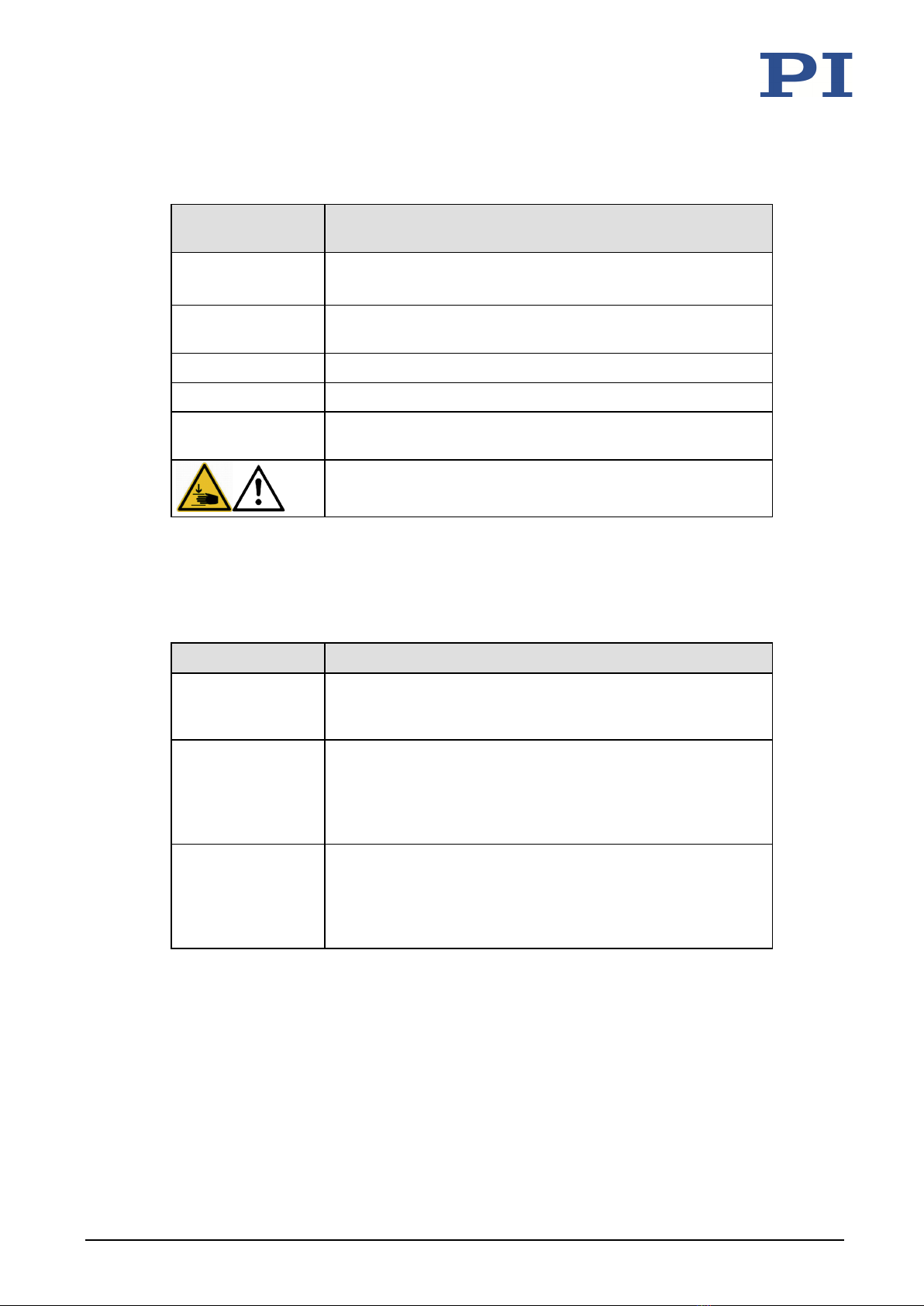
1.2 Symbols and Typographic Conventions...................................................................... 1
1.3 Definition.................................................................................................................... 2
1.4 Figures ........................................................................................................................ 2
1.5 Other Applicable Documents ..................................................................................... 3
1.6 Downloading Manuals................................................................................................ 3
2Safety 5
2.1 Intended Use .............................................................................................................. 5
2.2 General Safety Instructions ........................................................................................ 5
2.3 Organizational Measures............................................................................................ 6
3Product Description 7
3.1 Model Overview ......................................................................................................... 7
3.2 Product View .............................................................................................................. 9
3.3 Direction of Motion.................................................................................................... 9
3.4 Product Labeling....................................................................................................... 10
3.5 Scope of Delivery...................................................................................................... 11
3.6 Accessories ............................................................................................................... 12
3.7 Suitable Controllers .................................................................................................. 12
3.8 Technical Features.................................................................................................... 13
3.8.1 Encoder........................................................................................................ 13
3.8.2 Limit Switches.............................................................................................. 13
3.8.3 Reference Point Switch................................................................................ 13
3.8.4 Integrated PWM Amplifier .......................................................................... 13
4Unpacking 15
5Installation 17
5.1 General Notes on Installation................................................................................... 17
5.2 Mounting the L-509 onto a Surface ......................................................................... 19
5.3 Connecting the L-509 to the Protective Earth Conductor........................................ 22
5.4 Affixing the Load to the L-509 .................................................................................. 24
5.5 Setting Up a Multi-Axis System ................................................................................ 25
5.5.1 General Information on Setting Up a Multi-Axis System ............................ 25
5.5.2 Setting Up an XY System.............................................................................. 26
5.5.3 Setting Up a Z System.................................................................................. 28
5.6 Connecting the L-509 to the Controller.................................................................... 31
5.7 Connecting the Power Supply to the L-509.............................................................. 32
Contents

6Start-Up 33
6.1 General Notes on Start-Up....................................................................................... 33
6.2 Starting Up the stage................................................................................................ 36
6.2.1 L-509 Entries in the Stage Database of PI.................................................... 36
6.2.2 Operating Parameters of the Models with DC Motor................................. 37
6.2.3 Operating Parameters of the Models with Stepper Motor......................... 38
7Maintenance 39
7.1 General Notes on Maintenance ............................................................................... 39
7.2 Performing a Maintenance Run ............................................................................... 39
7.3 Cleaning the L-509.................................................................................................... 40
8Troubleshooting 41
8.1 Possible Causes and Correction................................................................................ 41
8.2 Moving the Platform Manually ................................................................................ 43
9Customer Service 45
10 Technical Data 47
10.1 Specifications............................................................................................................ 47
10.1.1 Data Table.................................................................................................... 47
10.1.2 Maximum Ratings........................................................................................ 50
10.1.3 Ambient Conditions and Classifications ...................................................... 51
10.1.4 Limit Switch Specifications .......................................................................... 51
10.1.5 Reference Point Switch Specifications ........................................................ 51
10.2 Dimensions ............................................................................................................... 52
10.2.1 L-509 Stage .................................................................................................. 52
10.2.2 Hole Pattern of the Moving Platform of the L-509...................................... 53
10.2.3 L-500.AV3 Adapter Bracket ......................................................................... 54
10.3 Tightening Torque for Screws, ISO 4762 - A2........................................................... 55
10.4 Pin Assignment ......................................................................................................... 56
10.4.1 HD Sub-D 26 (m) .......................................................................................... 56
10.4.2 Sub-D 15 (m)................................................................................................ 58
10.4.3 Sub-D 9 (m).................................................................................................. 59
10.4.4 M8 4-pin (m)................................................................................................ 59
11 Old Equipment Disposal 61
12 EC Declaration of Conformity 63

1 About this Document
L-509 Stage MP141E Version: 1.1.0 1
In this Chapter
Objective and Target Audience of this User Manual..................................................................... 1
Symbols and Typographic Conventions ......................................................................................... 1
Definition ....................................................................................................................................... 2
Figures............................................................................................................................................ 2
Other Applicable Documents......................................................................................................... 3
Downloading Manuals ................................................................................................................... 3
1.1 Objective and Target Audience of this User Manual
This manual contains information on the intended use of the L-509.
It assumes that the reader has a fundamental understanding of basic servo systems as well as
motion control concepts and applicable safety procedures.
The latest versions of the user manuals are available for download (p. 3) on our website.
1.2 Symbols and Typographic Conventions
The following symbols and typographic conventions are used in this user manual:
CAUTION
Dangerous situation
If not avoided, the dangerous situation will result in minor injury.
Actions to take to avoid the situation.
NOTICE
Dangerous situation
If not avoided, the dangerous situation will result in damage to the equipment.
Actions to take to avoid the situation.
INFORMATION
Information for easier handling, tricks, tips, etc.
1
About this Document

1 About this Document
2 Version: 1.1.0 MP141E L-509 Stage
Symbol/
Label Meaning
1.
2.
Action consisting of several steps whose sequential order must
be observed
Action consisting of one or several steps whose sequential
order is irrelevant
List item
p. 5 Cross-reference to page 5
RS-232 Labeling of an operating element on the product (example:
socket of the RS-232 interface)
Warning sign on the product which refers to detailed
information in this manual.
1.3 Definition
Term Definition
Load capacity Maximum load capacity in the vertical direction when the
stage is mounted horizontally. The contact point of the load is
in the center of the platform.
Max. push/pull
force
Maximum force in the direction of motion. Some stages may
have higher forces but with limited lifetimes. In the case of
vertical mounting, the specified value (p. 47) for models
without a gearhead and brake only applies when the servo
mode is on.
Linear encoder The linear encoder is an incremental sensor for capturing
changes in position. Signals from the sensor are used for axis
position feedback. After switching on the controller a
reference point definition must be performed before absolute
target positions can be commanded and reached.
1.4 Figures
For better understandability, the colors, proportions, and degree of detail in illustrations can
deviate from the actual circumstances. Photographic illustrations may also differ and must not
be seen as guaranteed properties.

1 About this Document
L-509 Stage MP141E Version: 1.1.0 3
1.5 Other Applicable Documents
The devices and software tools that are mentioned in this documentation are described in their
own manuals.
Product Document
Stages with electric motors MP146EK Short instructions for stages with electric
motors
C-863.11 DC Motor Controller MS205E User Manual
C-663.11 Stepper Motor Controller MS208E User Manual
C-884 DC Motor Controller MS213E User Manual
SMC Hydra Motion Controller Hardware Manual
1.6 Downloading Manuals
INFORMATION
If a manual is missing or problems occur with downloading:
Contact our customer service department (p. 45).
INFORMATION
For products that are supplied with software (CD in the scope of delivery), access to the
manuals is protected by a password. Protected manuals are only displayed on the website after
entering the password.
The password is included on the CD of the product.
For products with CD: Identify the password
1. Insert the product CD into the PC drive.
2. Switch to the Manuals directory on the CD.
3. In the Manuals directory, open the Release News (file including releasenews in the file
name).
4. Find the user name and the password in the section "User login for software download"
in the Release News.

1 About this Document
4 Version: 1.1.0 MP141E L-509 Stage
Downloading manuals
1. Open the website www.pi.ws.
2. If access to the manuals is protected by a password:
a) Click Login.
b) Log in with the user name and password.
3. Click Search.
4. Enter the product code up to the period (e.g., P-882) or the product family (e.g.,
PICMA® Bender) into the search field.
5. Click Start search or press the Enter key.
6. Open the corresponding product detail page in the list of search results:
c) If necessary: Scroll down the list.
d) If necessary: Click Load more results at the end of the list.
e) Click the corresponding product in the list.
7. Scroll down to the Downloads section on the product detail page.
The manuals are displayed under Documentation.
8. Click the desired manual and save it to the hard disk of your PC or to a data storage
medium.

2 Safety
L-509 Stage MP141E Version: 1.1.0 5
In this Chapter
Intended Use.................................................................................................................................. 5
General Safety Instructions............................................................................................................ 5
Organizational Measures............................................................................................................... 6
2.1 Intended Use
The L-509 is a laboratory device as defined by DIN EN 61010. It is intended for indoor use and
use in an environment that is free of dirt, oil and lubricants.
In accordance with its design and realization, the L-509 is intended for single-axis positioning,
adjusting and shifting of loads at different velocities. The L-509 is not intended for applications
in areas in which a failure would present severe risks to human beings or the environment.
The L-509 is intended for horizontal or vertical mounting. For the load limits with vertical
mounting, see "General Notes on Installation" (p. 17).
The intended use of the L-509 is only possible when completely mounted and connected.
The L-509 must be operated with a suitable controller (p. 12). The controller is not included in
the scope of delivery of the L-509.
2.2 General Safety Instructions
The L-509 is built according to state-of-the-art technology and recognized safety standards.
Improper use can result in personal injury and/or damage to the L-509.
Only use the L-509 for its intended purpose, and only use it if it is in a good working
order.
Read the user manual.
Immediately eliminate any faults and malfunctions that are likely to affect safety.
The operator is responsible for the correct installation and operation of the L-509.
2
Safety

2 Safety
6 Version: 1.1.0 MP141E L-509 Stage
2.3 Organizational Measures
User manual
Always keep this user manual available with the L-509.
The latest versions of the user manuals are available for download (p. 3) on our
website.
Add all information from the manufacturer to the user manual, for example
supplements or technical notes.
If you give the L-509 to other users, also include this user manual as well as other
relevant information provided by the manufacturer.
Only use the device on the basis of the complete user manual. Missing information due
to an incomplete user manual can result in minor injury and damage to equipment.
Only install and operate the L-509 after you have read and understood this user
manual.
Personnel qualification
The L-509 may only be installed, started up, operated, maintained, and cleaned by authorized
and appropriately qualified personnel.

3 Product Description
L-509 Stage MP141E Version: 1.1.0 7
In this Chapter
Model Overview............................................................................................................................. 7
Product View.................................................................................................................................. 9
Direction of Motion ....................................................................................................................... 9
Product Labeling .......................................................................................................................... 10
Scope of Delivery ......................................................................................................................... 11
Accessories................................................................................................................................... 12
Suitable Controllers ..................................................................................................................... 12
Technical Features ....................................................................................................................... 13
3.1 Model Overview
Classification of the stages
All models are electromotive linear positioning stages with precision leadscrew. They differ with
respect to:
Travel range
Drive type
Encoder equipment
L-509 Travel range in mm Travel range in inches (approx.)
.1xxxxx 26 1
.2xxxxx 52 2
.4xxxxx 102 4
L-509
Drive type Encoder type
ActiveDrive
DC Motor*
DC Gear
Motor
Stepper
Motor
Linear
encoder**
Rotary
encoder
.x0AD10 + +
.x4AD00 + +
.x0DG10 + +
.x0SD00 +
.xASD00** + +
* Separate power supply connection
** Separate sensor connection
3
Product Description

3 Product Description
8 Version: 1.1.0 MP141E L-509 Stage
Detailed Model Overview
Order number Product name
L-509.10AD10 Precision Linear Stage, 85 mm Wide, ActiveDrive DC Motor, 26 mm (1")
Travel Range, Optical Limit Switches
L-509.10DG10 Precision Linear Stage, 85 mm Wide, DC Gear Motor, 26 mm (1") Travel
Range, Optical Limit Switches
L-509.10SD00 Precision Linear Stage, 85 mm Wide, 2-Phase Stepper Motor, 26 mm (1")
Travel Range, Optical Limit Switches
L-509.14AD00 Precision Linear Stage, 85 mm Wide, ActiveDrive DC Motor, 26 mm (1")
Travel Range, Length Measuring System (Steel) with RS-422 Signal
Transmission, Optical Limit Switches
L-509.1ASD00 Precision Linear Stage, 85 mm Wide, 2-Phase Stepper Motor, 26 mm (1")
Travel Range, Linear Encoder with Sin/Cos Signal Transmission, Optical
Limit Switches
L-509.20AD10 Precision Linear Stage, 85 mm Wide, ActiveDrive DC Motor, 52 mm (2")
Travel Range, Optical Limit Switches
L-509.20DG10 Precision Linear Stage, 85 mm Wide, DC Gear Motor, 52 mm (2") Travel
Range, Optical Limit Switches
L-509.20SD00 Precision Linear Stage, 85 mm Wide, 2-Phase Stepper Motor, 52 mm (2")
Travel Range, Optical Limit Switches
L-509.24AD00 Precision Linear Stage, 85 mm Wide, ActiveDrive DC Motor, 52 mm (2")
Travel Range, Length Measuring System (Steel) with RS-422 Signal
Transmission, Optical Limit Switches
L-509.2ASD00 Precision Linear Stage, 85 mm Wide, 2-Phase Stepper Motor, 52 mm (2")
Travel Range, Linear Encoder with Sin/Cos Signal Transmission, Optical
Limit Switches
L-509.40AD10 Precision Linear Stage, 85 mm Wide, ActiveDrive DC Motor, 102 mm (4")
Travel Range, Optical Limit Switches
L-509.40DG10 Precision Linear Stage, 85 mm Wide, DC Gear Motor, 102 mm (4") Travel
Range, Optical Limit Switches
L-509.40SD00 Precision Linear Stage, 85 mm Wide, 2-Phase Stepper Motor, 102 mm (4")
Travel Range, Optical Limit Switches
L-509.44AD00 Precision Linear Stage, 85 mm Wide, ActiveDrive DC Motor, 102 mm (4")
Travel Range, Length Measuring System (Steel) with RS-422 Signal
Transmission, Optical Limit Switches
L-509.4ASD00 Precision Linear Stage, 85 mm Wide, 2-Phase Stepper Motor, 102 mm (4")
Travel Range, Linear Encoder with Sin/Cos Signal Transmission, Optical
Limit Switches
For further technical data, see the specifications (p. 47).

3 Product Description
L-509 Stage MP141E Version: 1.1.0 9
3.2 Product View
Figure 1: Parts of the L-509, examples: L-509.2ASD00 (left), L-509.20AD10 (right)
1
Motor
2Sensor unit (only L-509.xASD00 and L-509.x4AD00 models)
3Motion platform
4Base body
5Sensor connection (Sub-D 9 panel plug; only L-509.xASD00 models)
6Motor connection
(for L-509.x0SD00 / L-509.xASD00 / L-509.x0DG10: Panel plug HD Sub-D 26;
for L-509.x0AD10 / L-509.x4AD00: Sub-D 15 panel plug)
7Vibration absorber (only L-509.x0SD00 and L-509.xASD00 models)
8Power supply connection (M8 panel plug 4-pin, only L-509.x0AD10 and L-509.x4AD00 models)
3.3 Direction of Motion
Figure 2: Direction of motion of the platform
X (arrow direction:) Direction of motion on positive command

3 Product Description
10 Version: 1.1.0 MP141E L-509 Stage
3.4 Product Labeling
Figure 3: Product labeling
Position Labeling Description
1 Controller Motor connection
2 L-509.2ASD00 Product name (example), the characters following the
period refer to the model
2 415002159 Serial number (example), individual for each L-509
Meaning of the places (counting from left): 1 =
internal information, 2 and 3 = year of manufacture, 4
to 9 = consecutive numbers
2, 6
Manufacturer's logo
2, 7
Warning sign "Observe manual!"
2, 8 Country of origin: Germany Country of origin
2, 10
CE conformity mark
2, 11 WWW.PI.WS Manufacturer's address (website)
2, 12
Old equipment disposal
3 Sensor Linear encoder connection (only L-509.xASD00
models)
4, 5
Warning sign "Risk of crushing": Reference to
dangerous forces (p. 33)
9 L-509 Product series
13 Symbol for the protective earth conductor, marks the
protective earth connection of the L-509 (p. 22)

3 Product Description
L-509 Stage MP141E Version: 1.1.0 11
3.5 Scope of Delivery
Item number Component L-509 model.
L-509.xxxxxx Stage according to order (p.
7)
x0AD10 x4AD00 x0DG10 x0SD00 xASD00
Motor cable and, if
applicable, sensor cable
according to the ordered
controller
x x x x x
62345070 (for
L-509.1xxxxx)
or 62345016
(for
L-509.2xxxxx
and
L-509.4xxxxx)
Screw set for mounting the
stage
4 (or 8) socket head cap
screws, ISO 4762* M4x14
2 dowel pins,
ISO 8734** - 4 m6 x 12
x x x x x
MP146EK Short instructions for stages
with electric motors
x x x x x
7300900006-
0180
Power supply set, consisting
of:
C-663.PS wide-range-
input power supply, 24 V
/ 120 W
K050B0003 adapter for
power supply connection;
barrel connector to M8
4-pin. Connector (f)
K351000037 snap-on
ferrite suppressor
x x
K322000047
or
K322000074
EU or US power cord,
depending on country of
order
x x
* Corresponds to DIN 912
** Corresponds to DIN 6325

3 Product Description
12 Version: 1.1.0 MP141E L-509 Stage
3.6 Accessories
Order number Description
L-500.AV3 Mounting adapter for vertical mounting of L-509 stages, included
4 socket head cap screws ISO 4762* M6x12
2 dowel pins, ISO 8734** - 4 m6 x 12
2 dowel pins, ISO 8734** - 3 m6 x 12
* Corresponds to DIN 912
** Corresponds to DIN 6325
To order, contact our customer service department (p. 45).
3.7 Suitable Controllers
The L-509 must be connected to a suitable controller. The following controllers from PI are
suitable for operation of the L-509:
Drive type Controllers Axes per
controller
PC interface Multiple
controllers on
the same PC
Models
L-509
DC motor
C-663.11
C-663.12
1 USB, RS-232,
daisy chain
network
Yes, same
interface
.x0DG10,
.x0AD10,
.x4AD00
C-884 1 to 4 USB, RS-232,
TCP/IP
Yes .x0DG10,
.x0AD10,
.x4AD00
Stepper
motor
C-663 1 USB, RS-232,
Daisy chain
network
Yes, same
interface
.x0SD00
SMC Hydra 2 RS-232,
TCP/IP
Yes .xASD00
PC software is included in the scope of delivery of the controllers from PI. The operation of the
controllers is described in the corresponding user manuals.

3 Product Description
L-509 Stage MP141E Version: 1.1.0 13
3.8 Technical Features
3.8.1 Encoder
The L-509.x0SD00 models are not equipped with an encoder.
Linear encoder
The L-509.x4AD00 and L-509.xASD00 models are equipped with an optical linear encoder. For
the encoder resolution, refer to the table in the "Specifications" section (p. 47).
Optical linear encoders measure the actual position directly (direct metrology). Therefore,
errors occurring in the drive, such as nonlinearity, backlash or elastic deformations cannot
influence the measurement of the position.
Rotary encoder
The L-509.x0AD10 and L-509.x0DG10 models are equipped with an incremental rotary encoder.
A rotary encoder is implemented at a rotating point in the drivetrain, e.g., the motor shaft.
3.8.2 Limit Switches
The L-509 is equipped with optical limit switches.
Each limit switch sends its signal to the controller on a dedicated line. The controller then stops
the motion. If the controller does not stop the motion in time, the stage runs into the hard stop.
See "Limit Switch Specifications" (p. 51) for more information.
3.8.3 Reference Point Switch
The stage is equipped with a direction-sensing reference point switch, which is located at about
the midpoint of the travel range. This sensor sends a TTL signal indicating whether the stage is
on the positive or negative side of the reference point switch.
See the controller user manual and/or associated software manuals for the commands that
make use of the reference point signal.
3.8.4 Integrated PWM Amplifier
The L-509.x0AD10 and L-509.x4AD00 models with direct drive are equipped with a PWM
amplifier ("ActiveDrive concept"). The motor and PWM amplifier are installed in a common case
and thus optimally integrated and shielded. The PWM amplifier only receives the control signals
from the controller, whereas the supply voltage is provided via an external power supply. The
ActiveDrive concept allows high motor power and dynamics at low power loss.


4 Unpacking
L-509 Stage MP141E Version: 1.1.0 15
1. Unpack the L-509 with care.
2. Compare the contents with the items listed in the contract and the packing list.
3. Inspect the contents for signs of damage. If parts are missing or you notice signs of
damage, contact PI immediately.
4. Keep all packaging materials in case the product needs to be returned.
4
Unpacking

Other manuals for L-509
1
This manual suits for next models
15
Table of contents
Other PI Industrial Electrical manuals
Popular Industrial Electrical manuals by other brands

Eaton
Eaton MEMSHIELD 4 installation instructions

Vimar
Vimar SMART AUTOMATION BY-ME PLUS 01450 manual

KinCony
KinCony KC868-COL Instructions for the use

Murata
Murata GRM1555C1H271JA01 Series Reference sheet

Eaton
Eaton Memshield 3 Series Instruction leaflet

Murata
Murata GRT155R61E105KE01 Series Reference sheet

Hubbell
Hubbell GAI-TRONICS 400-001 General information

Murata
Murata GRM2165C1H361JA01 Series Reference sheet

SSS Siedle
SSS Siedle VNG 602-02 Product information

Murata
Murata GRM1887U1H152JA01 Series Reference sheet

Eaton
Eaton CEAG ZB-S Series installation instructions

ZURN
ZURN Z1196 Operation and maintenance instructions