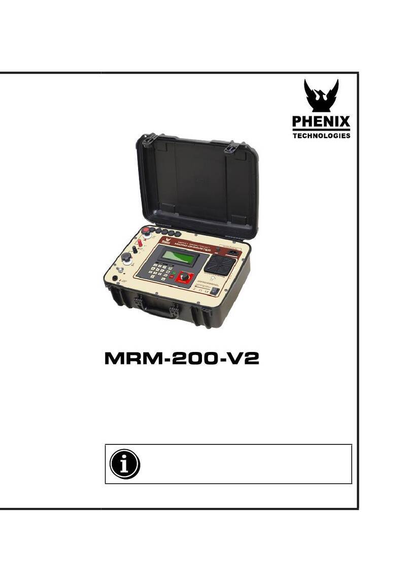
Phenix MRM-100 User manual

MRM 100
User’s Manual
Phenix Technologies Inc.
MICRO-OHMMETER
MODEL NUMBER MRM-100
Version 1.2
Rev 7/17/2018 nab

MRM 100
DANGER / GENERAL SAFETY PRECAUTIONS
WARNING !!
Complete Grounding of this unit is necessary for the safe
operation of this equipment. Disconnect inputs before un-
grounding this equipment
DANGER

MRM 100
TABLE OF CONTENTS
Section Number
WARNING / GENERAL SAFETY PRECAUTIONS
PRODUCT INFORMATION 1
-SAFETY AND CAUTION NOTES
-SPECIFICATIONS
-INTRODUCTION / THEORY OF OPERATION
CONTROLS AND INDICATORS 2
ELECTRICAL SET-UP 3
MRM MENU TREE 4
STARTING SCREENS 4-1
PERFORMING TESTS 4-2
SAVED RESULTS 4-6
SYSTEM SETUP 4-8
OPERATING INSTRUCTIONS 5
UNIT UNDER TEST 5-1
METER CHECK 5-2

MRM 100
TROUBLESHOOTING OPERATIONAL PROBLEMS 6
STORAGE OF EQUIPMENT 7
MAINTENANCE 8
RECOMMENDED SPARE PARTS 9
MRM-100 PARTS LIST 10
PARTS ORDERING INFORMATION 11
RETURNED MATERIAL 12
ELECTRICAL DIAGRAMS 13

MRM 100
DANGER / WARNINGS
GENERAL SAFETY PRECAUTIONS
HIGH VOLTAGE
This equipment is capable of providing POTENTIALLY LETHAL VOLTAGES!
Improper operation or test practices may result in injury or death to the operator or surrounding personnel.
The operation of High Voltage test equipment should only be performed by personnel familiar with HIGH VOLTAGE
testing and safety procedures. The operator of this equipment must be aware of all hazards associated with High
Voltage testing. The operator is responsible for himself and others in close proximity of the testing area.
CAUTION: Contact with the test leads on this equipment can cause harmful electrical shock. Do
not touch test leads while a test is in process.
Some General Safety Practices for working with High Voltage Test Equipment have been listed below for your
reference.
•Become familiar with your instrument before performing an actual test
•Know your work area, check that all circuits are de-energized and locked out.
•Never work alone; always work with another qualified worker.
•Mark off entire work area with barriers and warning tape.
•Make all personnel aware of your testing activities.
•Be aware of dangerous conditions that may arise from energizing a test specimen.
•Never modify test equipment; modifications to equipment could introduce an unknown hazard or hinder a
designed-in safety feature.

MRM 100
•DO NOT operate damaged equipment. Remove power, and do not use the equipment until safe operation can
be verified by service-trained personnel.
Phenix Technologies, Inc. assumes no liability for unsafe or improper use of test equipment.

MRM 100
1-2
PRODUCT SPECIFICATIONS
Input:
100 to 240 VAC, 50/60 Hz, single phase, 5 Amps.
Resistance Measurement Range:
1 to 240m, non-inductive.
Test Current:
10 to 105 Amps, selectable in 1 Amp steps.
Uncertainty:
+/- 1% of reading, +/- 0.4 at 100 Amps or +/-4 at 10 Amps.
Resolution:
1 to 199: 0.1
200 to 1999: 1
2.00mto 19.99m: .01m
20.0mto 240.0m: 0.1m
Termination:
30 foot cables with alligator clamps. C clamps are also available
Keyboard:
10 number keys, 26 letter keys, and 14 function keys.
Control:
Embedded microprocessor
Display:
4 X 20 LCD screen
Computer Port:
RS-232 ASCII Commands
Memory:
The MRM-100 can store up to 300 measurements in memory.
Type of Cooling:
Two cooling fans
Uncertainty Temperature Range:
18C to 27C (64F to 81F)
Operating Ambient Temperature:
-7C to 45C (19F to 113F)
Storage Temperature:

MRM 100
-20C to 57C (-4F to 135F)
Dimensions:
16.5” W x 15.25” D x 11.25” H (419 mm W x 388 mm D x 286 mm H)
Weight:
Unit: 28.5 lbs. (13 kg)
Cables/ Bag/Accessories: 19.5 lbs. (8.8 kg)

MRM 100
1-3
INTRODUCTION
The MRM-100 is a portable micro-Ohmmeter used to test circuit breaker contact resistance, or
anywhere low resistance measurements at currents up to just over 100 Amps are required. The
MRM-100 uses a low voltage, high current power supply to run a user-defined test current of
between 10 Amps to 105 Amps to any resistive load that requires no more than 2.5 Volts across it
to test. The MRM-100 does detect if the test is able to reach desired current, and allows for
immediately stopping the test.
THEORY OF OPERATION
The MRM-100 uses a two-voltmeter method where each voltage reading implements a four-wire
Kelvin connection. One voltmeter monitors the voltage across a known, highly stable shunt that
passes the test current through it, while the other voltmeter monitors the voltage across the unit
under test. A test current is then applied (see ANSI C37.09 and IEC 62771-100 for test current
requirements). This current is ramped up, held for a period of time and then ramped down. While
the current is relatively constant, the voltages across the known resistance and unit under test are
amplified and filtered. Then they are sampled several times by analog to digital converters to
reduce any noise, and processed by a microcontroller. The microcontroller calculates the ratio
between the test current and sensed voltage to determine the resistance. The micro-Ohmmeter is
designed to test resistances of 1 micro-Ohm to 240 milliohms.

MRM 100
2-1
SECTION 2: CONTROLS AND INDICATORS
1. AC Line Cord Input Connector:
Plug into a suitable grounded receptacle. See specifications for voltage and current requirements.
2. Main Power Switch:
Turning the switch On / Off energizes or de-energizes the MRM.
I
SERIAL I/O
0
AC INPUT
MODEL MRM-100
H
Y
N
Space
6
F
DG
A S
Esc
Z,
-/
.
V
C
XB
Q
1
R
ET
W
2354
Enter
KL
J
Start Stop
M
IP
O
U
8
70
9
SENSE
OFF ON
CURRENT
HIGH
MRM-100
PHENIX
TECHNOLOGIES
R
RS-232
OUTPUTS

MRM 100
3. RS-232 Port:
This port allows communication with a Personal Computer for data acquisition and remote control, when
supported by appropriate optional software.
4. LCD Display:
This 4x20 Character display, shows all relevant information during testing and setup.
5. Keypad:
This keypad is used to enter test parameters.
6. Built In Printer:
The built in dot matrix printer is designed to print test results immediately or to provide a printout of saved
tests.

MRM 100
2-2
CONTROLS AND INDICATORS (Continued)
7. High Current Output Connection
This receptacle is for connection of the high current output leads.
8. Output Energized Indicator:
This indicator illuminates under any of the following conditions:
a. A test is in progress.
No test cables should be connected, disconnected or handled while this light is on.
9. Output Sense Lead Connection:
This receptacle is for connection of the sense leads required for the four wire measurement.

MRM 100
3-1
SECTION 3: ELECTRICAL SET-UP
Line / Generator Powered Operation
Locate the desired location for the test set. Prepare the main power input cable for plugging into the proper
facility or generator power. Leave plug unconnected at this time. Ensure that generator is properly grounded with
facility ground or ground (earthing) rod.
Measurement Lead Connection
WARNING: Main power switch on front panel must be in the OFF position before proceeding. Ensure test
specimen is de-energized, discharged, and properly isolated!
1. Connect the measurement cables with red leads to the positive terminal (if applicable) of the unit under test.
2. Connect the measurement cables with black leads to the negative terminal (if applicable) of the unit under
test.
3. Connect the input main power cable to appropriate power source if powering with line power.
Note: Specimen connection points for test cables must be clean and corrosion free. Any contamination at
connection points may result in errant readings.

MRM 100
4-1
SECTION4: MRMMENUTREE
STARTING SCREENS
MRM START UP SCREEN
Press any key (except “Esc”) to proceed.
TEST OPERATOR ID SCREEN

MRM 100
Operator identification may be entered here and is shown on printouts as well as saved
tests. Leave blank if not wanted for test. To delete the existing entry, move cursor to the
left with left arrow and use delete key.
MRM MAIN MENU
The following numbers are keyed to the screen shot above.
1) If “1” is pressed, a test setup is begun.
2) If “2” is pressed, the operator identification can be altered.
3) If “3” is pressed, saved results can be recalled.
4) If “4” is pressed, the meter itself can be set up.
5) If “1” is pressed, the following screen is displayed.

MRM 100
4-2
PERFORMING TESTS
TEST DESCRIPTION SCREEN
Any information about the next test can be given here (up to 20 characters).
TEST CURRENT SET-UP

MRM 100
Any current from 10Amps to 105Amps (in one amp steps) can be entered here. The actual
test current will vary somewhat from the entered current but will be close. If current as
entered results in a level slightly below the minimum or slightly above the maximum
allowed for test, entry can be changed by one amp steps to bring current level within
specification.

MRM 100
4-3
READY FOR TEST SCREEN
When “Enter” is pressed, the meter shows the following screen:
This screen shows information about the test and how to begin.
1) This shows at what current the test will be at.
2) This displays the test ID information entered.
3) The green “Start” button on the keypad begins the test.
TEST IN PROGRESS SCREEN
This screen is what is shown while the test is running.

MRM 100
1) This is the approximate current the test is run at.
2) This is the current being measured. This should ramp
up to about the current shown on the first line.
3) If the test current is to be cut off, press the red “Stop”
button on the keypad.
4) This warns the user (along with the beeper and the red warning light) there may
be a high current going through the test cables.
When the test is completed, the following screen will appear.

MRM 100
4-4
RESULT SCREEN
This shows the measured resistance as well as the actual test current. The top line is shown
only until “S” is pressed. The last line gives options as well as affirms these are the results.
To return to the Main Menu from this screen, press “ENTER” and “Esc”
If “Enter” is pressed, the following screen appears.
CONTINUE SCREEN
Table of contents
Other Phenix Measuring Instrument manuals