®
AUDIO MIXER
OWNER’S MANUAL
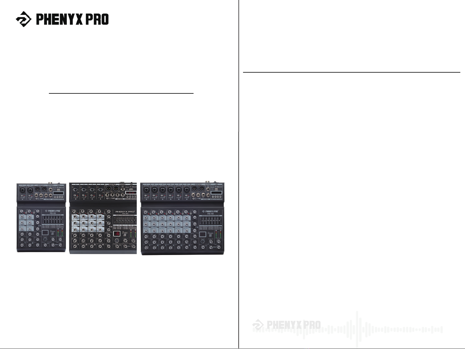
PRX-500
PRX-600
PRX-700
®
1
Table of Contents
System Description..............................................................................................................................4
Important Safety Instructions...............................................................................................................5
System overview................................................................................................................................4
Box content........................................................................................................................................4
Warning.............................................................................................................................................5
Maintenance......................................................................................................................................5
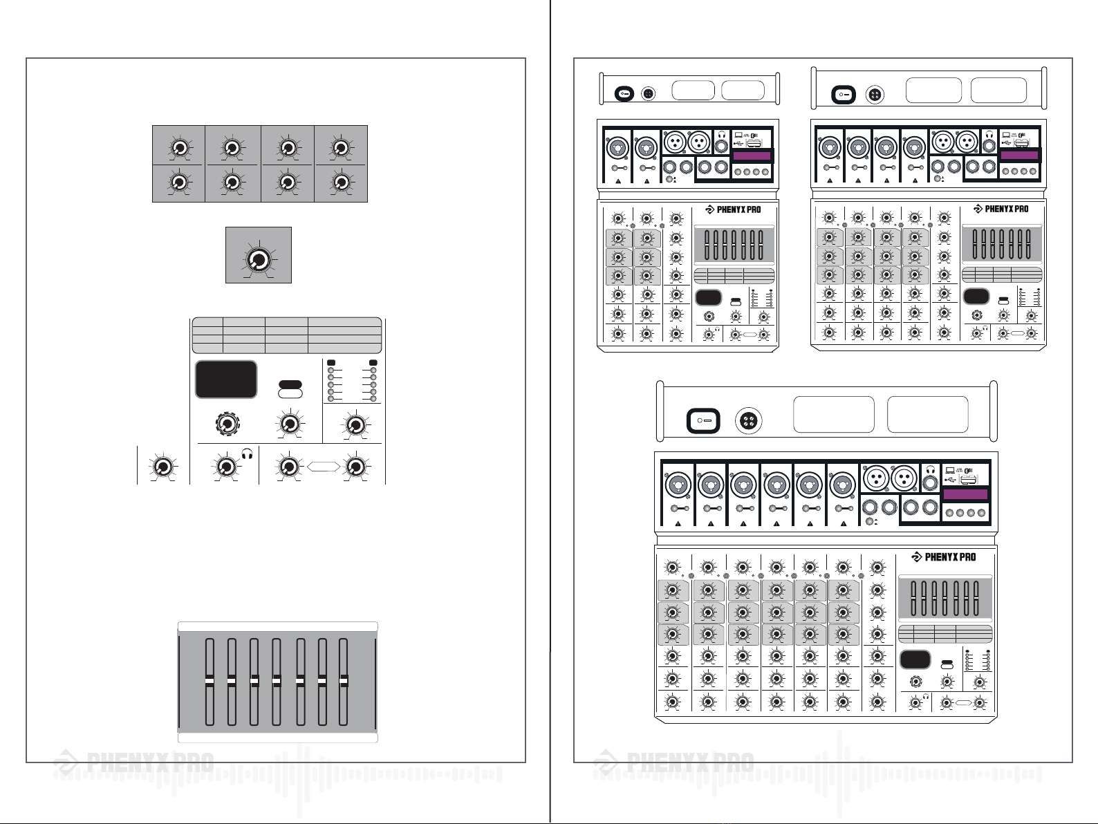
Front panel.......................................................................................................................................10
Rear panel.......................................................................................................................................14
Input channel section..................................................................................................................10
Master control section...............................................................................................................12
USB interface section................................................................................................................13
16 DSP section............................................................................................................................13
Operation Guidance............................................................................................................................6
Functions of Parts...............................................................................................................................9
Troubleshooting................................................................................................................................15
Specification......................................................................................................................................15
Technical Support & Warranty Information....................................................................................17
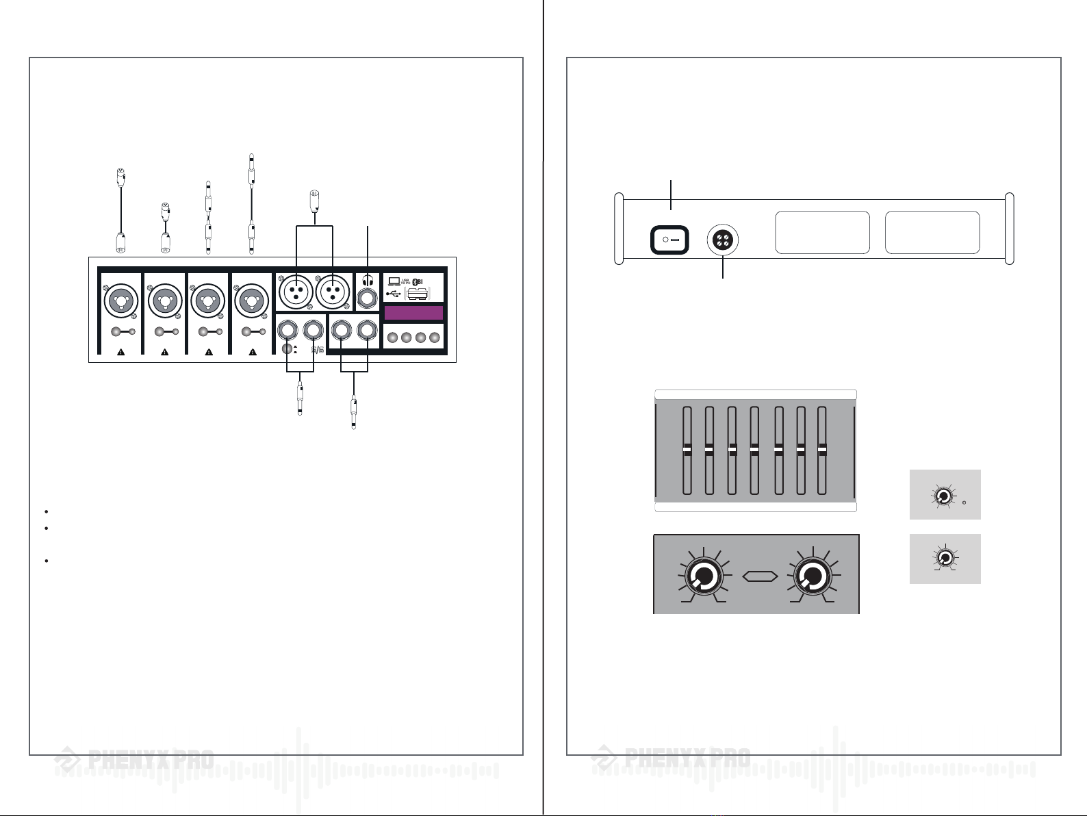
STEP 1: Connect inputs...................................................................................................................6
STEP 2: Connect outputs....................................................................................................................6
STEP 3: Powering up the system..........................................................................................................7
STEP 4: Getting sound to the speaker...............................................................................................7
STEP 5: Getting sound to the monitor................................................................................................8
STEP 6: Using the 16 DSP effects......................................................................................................8
STEP 7: Using the 7-Band Stereo Graphic Equalizer............................................................................8
Thank you for purchasing the Phenyx Pro
PRX Series (PRX-500, PRX-600, PRX-700). For the
best results and the utmost satisfaction for your new unit,
please read this manual carefully to ensure proper operation,
and keep it for future reference. For more information,
please visit our store: www.phenyxpro.com