Philips Signage Solutions BDL4678XL User manual

www.philips.com/welcome
BDL4678XL
User Manual (English)

BDL4678XL
ii
Safety Instructions
Safety precautions and maintenance
WARNING: Use of controls, adjustments or procedures other than those specied in this documentation may result in exposure to
shock, electrical hazards and/or mechanical hazards.
Read and follow these instructions when connecting and using your display:
Operation:
• Keepthedisplayoutofdirectsunlightandawayfromstovesoranyotherheatsources.
• Removeanyobjectthatcouldfallintoventilationholesorpreventpropercoolingofthedisplay’selectronics.
• Donotblocktheventilationholesonthecabinet.
• Whenpositioningthedisplay,makesurethepowerplugandoutletareeasilyaccessible.
• Whenturningoffthedisplaybydetachingthepowercord,wait6secondsbeforere-attachingthepowercordfornormaloperation.
• EnsuretheuseofanapprovedpowercordprovidedbyPhilipsatalltimes.Ifyourpowercordismissing,pleasecontactyourlocalservicecenter.
• Donotsubjectthedisplaytoseverevibrationorhighimpactconditionsduringoperation.
• Donotknockordropthedisplayduringoperationortransportation.
Maintenance:
• Toprotectyourdisplayfrompossibledamage,donotputexcessivepressureontheLCDpanel.Whenmovingyourdisplay,grasptheframetolift;do
notliftthedisplaybyplacingyourhandorngersontheLCDpanel.
• Unplugthedisplayifyouarenotgoingtouseitforanextensiveperiodoftime.
• Unplugthedisplayifyouneedtocleanitwithaslightlydampcloth.Thescreenmaybewipedwithadryclothwhenthepowerisoff.However,never
useorganicsolvent,suchas,alcohol,orammonia-basedliquidstocleanyourdisplay.
• Toavoidtheriskofshockorpermanentdamagetotheset,donotexposethedisplaytodust,rain,wateroranexcessivelymoistenvironment.
• Ifyourdisplaybecomeswet,wipeitwithdryclothassoonaspossible.
• Ifaforeignsubstanceorwatergetsinyourdisplay,turnthepoweroffimmediatelyanddisconnectthepowercord.Thenremovetheforeignsubstance
orwater,andsendtheunittothemaintenancecenter.
• Donotstoreorusethedisplayinlocationsexposedtoheat,directsunlightorextremecold.
• Inordertomaintainthebestperformanceofyourdisplayandensurealongerlifetime,westronglyrecommendusingthedisplayinalocationthatfalls
withinthefollowingtemperatureandhumidityranges.
-Temperature:0-40°C32-104°F
-Humidity:20-80%RH
IMPORTANT:Alwaysactivateamovingscreensaverprogramwhenyouleaveyourdisplayunattended.Alwaysactivateaperiodicscreenrefresh
applicationiftheunitwilldisplayunchangingstaticcontent.Uninterrupteddisplayofstillorstaticimagesoveranextendedperiodmaycause“burnin”,
alsoknownas“after-imaging”or“ghostimaging”,onyourscreen.Thisisawell-knownphenomenoninLCDpaneltechnology.Inmostcases,the“burned
in”or“after-imaging”or“ghostimaging”willdisappeargraduallyoveraperiodoftimeafterthepowerhasbeenswitchedoff.
WARNING:Severe“burn-in”or“after-image”or“ghostimage”symptomswillnotdisappearandcannotberepaired.Thisisalsonotcoveredunderthe
termsofyourwarranty.
Service:
• Thecasingcovershouldbeopenedonlybyqualiedservicepersonnel.
• Ifthereisanyneedforrepairorintegration,pleasecontactyourlocalservicecenter.
• Donotleaveyourdisplayunderdirectsunlight.
Ifyourdisplaydoesnotoperatenormally,havingfollowedtheinstructionssetoutinthisdocument,pleasecontactatechnicianoryour
localservicecenter..

BDL4678XL
iii
Read and follow these instructions when connecting and using your display:
• Unplugthedisplayifyouarenotgoingtouseitforanextensiveperiodoftime.
• Unplugthedisplayifyouneedtocleanitwithaslightlydampcloth.Thescreenmanybewipedwithadryclothwhenthepoweris
off.However,neverusealcohol,solventsorammonia-basedliquids.
• Consultaservicetechnicianifthedisplaydoesnotoperatenormallywhenyouhavefollowedtheinstructionsinthismanual.
• Thecasingcovershouldbeopenedonlybyqualiedservicepersonnel.
• Keepthedisplayoutofdirectsunlightandawayfromstovesoranyotherheatsources.
• Removeanyobjectthatcouldfallintotheventsorpreventpropercoolingofthedisplay’selectronics.
• Donotblocktheventilationholesonthecabinet.
• Keepthedisplaydry.Toavoidelectricshock,donotexposeittorainorexcessivemoisture.
• WhenturningoffthedisplaybydetachingthepowercableorDCpowercord,waitfor6secondsbeforere-attachingthepower
cableorDCpowercordfornormaloperation..
• Toavoidtheriskofshockorpermanentdamagetothesetdonotexposethedisplaytorainorexcessivemoisture.
• Whenpositioningthedisplay,makesurethepowerplugandoutletareeasilyaccessible.
• IMPORTANT:Alwaysactivateascreensaverprogramduringyourapplication.Ifastillimageinhighcontrastremainsonthe
screenforanextendedperiodoftime,itmayleavean‘after-image’or‘ghostimage’onthefrontofthescreen.Thisisawell-known
phenomenonthatiscausedbytheshortcomingsinherentinLCDtechnology.Inmostcasestheafterimagewilldisappeargradually
overaperiodoftimeafterthepowerhasbeenswitchedoff.Beawarethattheafter-imagesymptomcannotberepairedandisnot
coveredunderwarranty.

BDL4678XL
iv
Regulatory Information
CE Declaration of Conformity
Wedeclareunderourresponsibilitythattheproductisinconformitywiththefollowingstandards:
• EN60950-1:2006+A11:2009+A1:2010+A12:2011(SafetyrequirementofInformationTechnologyEquipment).
• EN55022:2010(RadioDisturbancerequirementofInformationTechnologyEquipment).
• EN55024:2010(ImmunityrequirementofInformationTechnologyEquipment).
• EN61000-3-2:2006+A1:2009+A2:2009(LimitsforHarmonicCurrentEmission).
• EN61000-3-3:2008(LimitationofVoltageFluctuationandFlicker)
• EN50581:2012(Technicaldocumentationfortheassessmentofelectricalandelectronicproductswithrespecttotherestrictionofhazardous
substances)
followingprovisionsofdirectivesapplicable.
• 2006/95/EC(LowVoltageDirective).
• 2004/108/EC(EMCDirective).
• 2009/125/EC(ErP,Energy-relatedProductDirective,ECNo.1275/2008and642/2009Implementing)
• 2011/65/EU(RoHSDirective)andisproducedbyamanufacturingorganizationonISO9000level.
Federal Communications Commission (FCC) Notice (U.S. Only)
ThisequipmenthasbeentestedandfoundtocomplywiththelimitsforaClassBdigitaldevice,pursuanttopart15oftheFCCRules.
Theselimitsaredesignedtoprovidereasonableprotectionagainstharmfulinterferenceinaresidentialinstallation.Thisequipment
generates,usesandcanradiateradiofrequencyenergyand,ifnotinstalledandusedinaccordancewiththeinstructions,maycause
harmfulinterferencetoradiocommunications.However,thereisnoguaranteethatinterferencewillnotoccurinaparticularinstallation.
Ifthisequipmentdoescauseharmfulinterferencetoradioortelevisionreception,whichcanbedetermined
byturningtheequipmentoffandon,theuserisencouragedtotrytocorrecttheinterferencebyoneormoreofthefollowing
measures:
• Reorientorrelocatethereceivingantenna.
• Increasetheseparationbetweentheequipmentandreceiver.
• Connecttheequipmentintoanoutletonacircuitdifferentfromthattowhichthereceiverisconnected.
• Consultthedealeroranexperiencedradio/TVtechnicianforhelp.
Changesormodicationsnotexpresslyapprovedbythepartyresponsibleforcompliancecouldvoidtheuser’sauthoritytooperatethe
equipment.
UseonlyanRFshieldedcablethatwassuppliedwiththedisplaywhenconnectingthisdisplaytoacomputerdevice.
Topreventdamagewhichmayresultinreorshockhazard,donotexposethisappliancetorainorexcessivemoisture.
THISCLASSBDIGITALAPPARATUSMEETSALLREQUIREMENTSOFTHECANADIANINTERFERENCE-CAUSINGEQUIPMENTREGULATIONS.
ThisdevicecomplieswithPart15oftheFCCRules.Operationissubjecttothefollowingtwoconditions:(1)thisdevicemaynot
causeharmfulinterference,and(2)thisdevicemustacceptanyinterferencereceived,includinginterferencethatmaycauseundesired
operation.

BDL4678XL
v
Polish Center for Testing and Certication Notice
Theequipmentshoulddrawpowerfromasocketwithanattachedprotectioncircuit(athree-prongsocket).Allequipmentthatworkstogether(computer,
display,printer,andsoon)shouldhavethesamepowersupplysource.
Thephasingconductoroftheroom’selectricalinstallationshouldhaveareserveshort-circuitprotectiondeviceintheformofafusewithanominalvalue
nolargerthan16amperes(A).
Tocompletelyswitchofftheequipment,thepowersupplycablemustberemovedfromthepowersupplysocket,whichshouldbelocatednearthe
equipmentandeasilyaccessible.
Aprotectionmark“B”conrmsthattheequipmentisincompliancewiththeprotectionusagerequirementsofstandardsPN-93/T-42107andPN-89/
E-06251.
Electric, Magnetic and Electronmagnetic Fields (“EMF”)
1. Wemanufactureandsellmanyproductstargetedatconsumers,which,likeanyelectronicapparatus,ingeneralhavetheabilitytoemitandreceive
electromagneticsignals.
2. OneofourleadingBusinessPrinciplesistotakeallnecessaryhealthandsafetymeasuresforourproducts,tocomplywithallapplicablelegal
requirementsandtostaywellwithintheEMFstandardsapplicableatthetimeofproducingtheproducts.
3. Wearecommittedtodevelop,produceandmarketproductsthatcausenoadversehealtheffects.
4. Weconrmthatifitsproductsarehandledproperlyfortheirintendeduse,theyaresafetouseaccordingtoscienticevidenceavailabletoday.
5. WeplayanactiveroleinthedevelopmentofinternationalEMFandsafetystandards,enablingustoanticipatefurtherdevelopmentsinstandardization
forearlyintegrationinitsproducts.

BDL4678XL
vi
Information for U.K. only
(A)
(B)
WARNING -THIS APPLIANCE MUST BE EARTHED.
Important:
Thisapparatusissuppliedwithanapprovedmoulded13Aplug.Tochangeafuseinthistypeofplug
proceedasfollows:
1. Removefusecoverandfuse.
2. FitnewfusewhichshouldbeaBS13625A,A.S.T.A.orBSIapprovedtype.
3. Retthefusecover.
Ifthettedplugisnotsuitableforyoursocketoutlets,itshouldbecutoffandanappropriate3-pin
plugttedinitsplace.
Ifthemainsplugcontainsafuse,thisshouldhaveavalueof5A.Ifaplugwithoutafuseisused,thefuse
atthedistributionboardshouldnotbegreaterthan5A.
NOTE: Theseveredplugmustbedestroyedtoavoidapossibleshockhazardshoulditbeinserted
intoa13Asocketelsewhere.
How to connect a plug
Thewiresinthemainsleadarecolouredinaccordancewiththefollowingcode:
BLUE-“NEUTRAL”(“N”)
BROWN-“LIVE”(“L”)
GREEN&YELLOW-“EARTH”(“E”)
1. TheGREEN&YELLOWwiremustbeconnectedtotheterminalintheplugwhichismarkedwith
theletter“E”orbytheEarthsymbolorcolouredGREENorGREEN&YELLOW.
2. TheBLUEwiremustbeconnectedtotheterminalwhichismarkedwiththeletter“N”orcoloured
BLACK.
3. TheBROWNwiremustbeconnectedtotheterminalwhichmarkedwiththeletter“L”or
colouredRED.
Beforereplacingtheplugcover,makecertainthatthecordgripisclampedoverthesheathofthelead
-notsimplyoverthethreewires.

BDL4678XL
vii
China RoHS
中国电子信息产品污染控制标识要求 (中国RoHS法规标示要求) 产品中有毒有害物质或元素
的名称及含量
部件名称
有毒有害物质或元素
铅
(Pb)
汞
(Hg)
镉
(Cd)
六价铬
(Cr 6+)
多溴联苯
(PBB)
多溴二苯醚
(PBDE)
外壳 O O O O O O
液晶面板 X O O O O O
电路板组件 X O O O O O
附件
(遥控器,电源线,连接线)X O O O O O
遥控器电池 X O O O O O
O: 表示该有毒有害物质在该部件所有均质材料中的含量均在 SJ/T11363-2006 标准规定的限量要求以下.
X: 表示该有毒有害物质至少在该部件的某一均质材料中的含量超出 SJ/T11363-2006 标准规定的限量要求.
10 環保使用期限
此標識指期限(十年),電子信息產品中含有的有毒有害物質或元素在正常使用的條件下不會發生外泄或突變
,電子信息產品用戶使用該電子信息產品不會對環境造成嚴重污染或對其人身、財產造成嚴重損害的期限。

BDL4678XL
viii
North Europe (Nordic Countries) Information
Placering/Ventilation
VARNING:
FÖRSÄKRADIGOMATTHUVUDBRYTAREOCHUTTAGÄRLÄTÅTKOMLIGA,NÄRDUSTÄLLERDINUTRUSTNINGPÅPLATS.
Placering/Ventilation
ADVARSEL:
SØRGVEDPLACERINGENFOR,ATNETLEDNINGENSSTIKOGSTIKKONTAKTERNEMTTILGÆNGELIGE.
Paikka/Ilmankierto
VAROITUS:
SIJOITALAITESITEN,ETTÄVERKKOJOHTOVOIDAANTARVITTAESSAHELPOSTIIRROTTAAPISTORASIASTA.
Plassering/Ventilasjon
ADVARSEL:
NÅRDETTEUTSTYRETPLASSERES,MÅDUPASSEPÅATKONTAKTENEFORSTØMTILFØRSELERLETTEÅNÅ.
End-of-Life Disposal
YournewPublicInformationDisplaycontainsmaterialsthatcanberecycledandreused.Specializedcompaniescanrecycleyourproducttoincreasethe
amountofreusablematerialsandtominimizetheamounttobedisposedof.
PleasendoutaboutthelocalregulationsonhowtodisposeofyourolddisplayfromyourlocalPhilipsdealer.
(For customers in Canada and U.S.A.)
Thisproductmaycontainleadand/ormercury.Disposeofinaccordancetolocal-stateandfederalregulations.Foradditionalinformationonrecycling
contactwww.eia.org(ConsumerEducationInitiative)
Waste Electrical and Electronie Equipment-WEEE
Attention users in European Union private households
Thismarkingontheproductoronitspackagingillustratesthat,underEuropeanDirective2012/19/EUgoverningusedelectricaland
electronicappliances,thisproductmaynotbedisposedofwithnormalhouseholdwaste.Youareresponsiblefordisposalofthis
equipmentthroughadesignatedwasteelectricalandelectronicequipmentcollection.Todeterminethelocationsfordroppingoffsuch
wasteelectricalandelectronic,contactyourlocalgovernmentofce,thewastedisposalorganizationthatservesyourhouseholdorthe
storeatwhichyoupurchasedtheproduct.
Attention users in United States:
PleasedisposeofaccordingtoallLocal,StateandFederalLaws.Forthedisposalorrecyclinginformation,contact:www.mygreenelectronics.comorwww.
eiae.org.
End of Life Directives-Recycling
YournewPublicInformationDisplaycontainsseveralmaterialsthatcanberecycledfornewusers.
PleasedisposeofaccordingtoallLocal,State,andFederallaws.

BDL4678XL
ix
Table Of Contents
4.1.1. NavigatingtheOSDmenuusingthe
remotecontrol........................................16
4.1.2. NavigatingtheOSDmenuusingthe
display’scontrolbuttons....................16
4.2. OSDMenuOverview........................................16
4.2.1. Picturemenu............................................16
4.2.2. Screenmenu............................................17
4.2.3. Audiomenu..............................................18
4.2.4. PIPmenu....................................................18
4.2.5. Conguration1menu..........................19
4.2.6. Conguration2menu..........................20
4.2.7. Advancedoptionmenu.....................20
5. Input Mode..............................................................25
6. Pixel Defect Policy.................................................26
6.1. PixelsandSub-Pixels............................................26
6.2. TypesofPixelDefects+DotDenition. 26
6.3. BrightDotDefects...............................................26
6.4. DarkDotDefects.................................................27
6.5. ProximityofPixelDefects................................27
6.6. PixelDefectTolerances......................................27
6.7. MURA..........................................................................27
7. Cleaning and Troubleshooting.............................28
7.1. Cleaning......................................................................28
7.2. Troubleshooting......................................................29
8. Technical Specications........................................30
1. Unpacking and Installation..................................... 1
1.1. Unpacking.....................................................................1
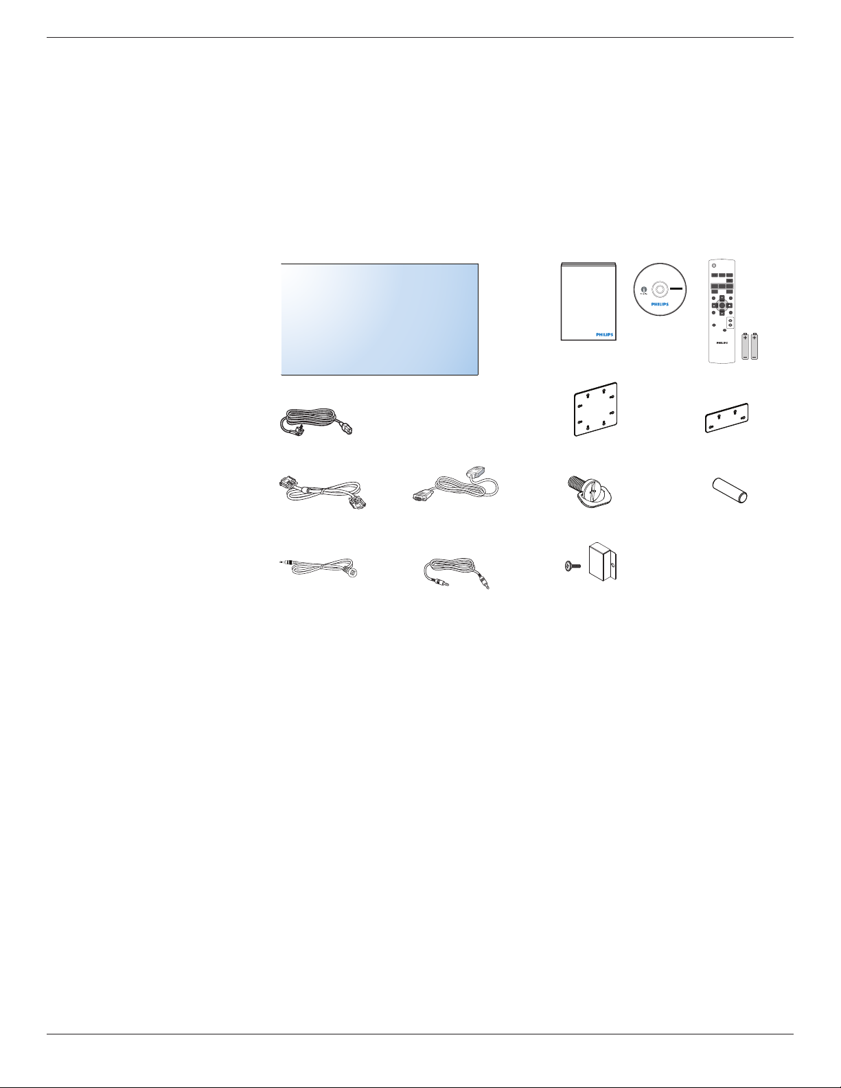
1.2. PackageContents.....................................................1
1.3. InstallationNotes......................................................1
1.4. InstallingandRemovingTableStands
(optional).......................................................................2
1.5. MountingonaWall.................................................3
1.5.1. VESAGrid....................................................3
1.6. MountinginPortraitPosition.............................4
1.7. OperatingInstructionsofEdgeAlignment
Kit/Pin...........................................................................4
1.7.1. InstallingEdgeAlignmentPin.............5
1.7.2. InstallingEdgeAlignmentKit..............5
1.8. InstallingOPSdevice...............................................7
2. Parts and Functions................................................. 8
2.1. ControlPanel..............................................................8
2.2. Input/OutputTerminals.........................................9
2.3. RemoteControl.....................................................10
2.3.1. Generalfunctions..................................10
2.3.2. Insertingthebatteriesintheremote
control..........................................................11
2.3.3. Handlingtheremotecontrol..........11
2.3.4. Operatingrangeoftheremote
control..........................................................11
3. Connecting External Equipment ........................12
3.1. ConnectingExternalEquipment...................12
3.2. ConnectingRemoteControl..........................13
3.2.1. SingleDisplayControl.......................13
3.2.2. IRPassThroughControl..................13
3.3. ConnectingMultipleDisplaysinaDaisy-
chainConguration..............................................14
3.3.1. Displaycontrolconnection..............14
3.3.2. Digitalvideoconnection....................14
3.3.3. Analogvideoconnection..................14
3.3.4. IRdaisy-chainConnection................15
4. OSD Menu ..............................................................16
4.1. NavigatingtheOSDMenu.............................16

BDL4678XL
1
1. Unpacking and Installation
1.1. Unpacking
• Thisproductispackedinacarton,togetherwiththestandardaccessories.
• Anyotheroptionalaccessorieswillbepackedseparately.
• Duetothesizeandweightofthisdisplayitisrecommendedfortwopeopletomoveit.
• Afteropeningthecarton,ensurethatthecontentsarecompleteandingoodcondition.
1.2. Package Contents
Pleaseverifythatyoureceivedthefollowingitemswithyourpackagecontent:
• LCDdisplay
• CDROM
• RemotecontrolwithAAAbatteries
• Powercord(1.8m)
• VGAcable(1.8m)
• RS232cable(3m)
• IRsensorcable(1.8m)
• 3.5mmJackIRcable(1.8m)
• Quickstartguide
• Powerswitchcover
• ScrewforPowerswitchcover(M3,
8mmx1)
• EdgeAlignmentKit-1:1PCS
• EdgeAlignmentKit-2:2PCS
• Screw:8PCS
• EdgeAlignmentPin:2PCS
* The supplied power cord varies depending on destination.
Power Cord
Video Signal Cable
(D-SUB to D-SUB Cable)
RS232 Cable
POWER
SMART
VIDEO
SOURCE
PIP
INPUTON/OFF CHANGE
BRIGHTNESSCONTRAST
DISPLAY
AUTO
ADJUST
MUTE
VOLUP
VOLDOWN
EXIT
MENU
SET
AUDIO
SOURCE
USBMENU
Remote Control
and AAA Batteries
CD ROM
Quick start guide
IR Sensor Cable IR Cable
Edge Alignment Kit-1 Edge Alignment Kit-2
Edge Alignment Pin
Screw
Power switch cover
and screw (M3x8) x1
NOTES:
• Forallotherregions,applyapowercordthatconformstotheACvoltageofthepowersocketandhasbeenapprovedbyandcomplieswiththe
safetyregulationsoftheparticularcountry.
• Youmightliketosavethepackageboxandpackingmaterialforshippingthedisplay.
1.3. Installation Notes
• Duetothehighpowerconsumption,alwaysusetheplugexclusivelydesignedforthisproduct.Ifanextendedlineisrequired,pleaseconsultyour
serviceagent.
• Theproductshouldbeinstalledonaatsurfacetoavoidtipping.Thedistancebetweenthebackoftheproductandthewallshouldbemaintained
forproperventilation.Avoidinstallingtheproductinthekitchen,bathroomoranyotherplaceswithhighhumiditysoasnottoshortentheservicelife
oftheelectroniccomponents.
• Theproductcannormallyoperateonlyunder3000minaltitude.Ininstallationsataltitudesabove3000m,someabnormalitiesmaybeexperienced.

BDL4678XL
2
1.4. Installing and Removing Table Stands (optional)
To install table stands:
1. Ensureyourdisplayispoweredoff.
2. Spreadaprotectivesheetonaatsurface.
3. Grabthecarryinghandlesandplacethedisplayface-downontheprotectivesheet.
4. Afterinsertingthestandintheguideblock,tightenthescrewsonbothsidesofthedisplay.
NOTE: Thelongersideofthestandshouldfacethefrontofthedisplay.
Carrying handle
Thumbscrews
Table stand
Longer portions face to front
To remove table stands:
1. Poweroffthedisplay.
2. Spreadaprotectivesheetonaatsurface.
3. Grabthecarryinghandlesandplacethedisplayface-downontheprotectivesheet.
4. Removescrewsusingascrewdriverandplacetheminasafeplaceforreuse.

BDL4678XL
3
1.5. Mounting on a Wall
Tomountthisdisplaytoawall,youwillhavetoobtainastandardwall-mountingkit(commerciallyavailable).Werecommendusingamountinginterface
thatcomplieswithTUV-GSand/orUL1678standardinNorthAmerica.
Protective Sheet
VESA Grid
Table Tabletop stand
1. Layaprotectivesheetonatable,whichwaswrappedaroundthedisplaywhenitwaspackaged,beneaththescreensurfacesoasnottoscratchthe
screenface.
2. Ensureyouhaveallaccessoriesformountingthisdisplay(wallmount,ceilingmount,tablestand,etc).
3. Followtheinstructionsthatcomewiththebasemountingkit.Failuretofollowcorrectmountingprocedurescouldresultindamagetotheequipment
orinjurytotheuserorinstaller.Productwarrantydoesnotcoverdamagecausedbyimproperinstallation.
4. Forthewall-mountingkit,useM6mountingscrews(havingalength10mmlongerthanthethicknessofthemountingbracket)andtightenthem
securely.
1.5.1. VESA Grid
BDL4678XL 400(H)x200(V)mm
200(H)x200(V)mm
Caution:
Topreventthedisplayfromfalling:
• Forwallorceilinginstallation,werecommendinstallingthedisplaywithmetalbracketswhicharecommerciallyavailable.Fordetailedinstallation
instructions,refertotheguidereceivedwiththerespectivebracket.
• Tolessentheprobabilityofinjuryanddamageresultingfromfallofthedisplayincaseofearthquakeorothernaturaldisaster,besuretoconsultthe
bracketmanufacturerforinstallationlocation.
Ventilation Requirements for enclosure locating
Toallowheattodisperse,leavespacebetweensurroundingobjectsasshowninthe
diagrambelow.
100 mm 100 mm
100 mm
100 mm

BDL4678XL
4
1.6. Mounting in Portrait Position
Thisdisplaycanbeinstalledinportraitposition.
1. Removethetablestand,ifattached.
2. Rotate90degreesanticlockwise.The“ ”logoshouldbebristlingwhenfacingthedisplayattheback.
90 90
1.7. Operating Instructions of Edge Alignment Kit / Pin
1
2
2
2
2

BDL4678XL
5
1.7.1. Installing Edge Alignment Pin
• Duringmountingdisplaystovideowallframe,using“EdgeAlignmentPin”tosecuretheatnessofadjacentdisplays.
• Don’tletedgealignmentpintotouchthesidesurfaceofpanel,panelwilldamageduetoincorrectinstallation.
• Using“EdgeAlignmentPin”onadjacentdisplays.
Thereare8holesonthefourcornersofdisplaysdesignedforplug-intheedgealignmentpin.
1.7.2. Installing Edge Alignment Kit
• Beforeinstalledgealignmentkit,displaysmustbemountedtovideowallframecorrectly.
• Using“EdgeAlignmentKit-1”onadjacentfourdisplays.
1
23
4
5
6
7
8

BDL4678XL
6
• Install“EdgeAlignmentKit-1”with8PCSofscrewonouter,biggerholes.
1
23
4
5
6
7
8
• Using“EdgeAlignmentKit-2”onadjacenttwodisplays.
1
2 3
4
• Install“EdgeAlignmentKit-2”with4PCSofscrewonouter,biggerholes.
1
2 3
4

BDL4678XL
7
1.8. Installing OPS device
ToinstallOPSdevicetodisplay:
1. Removethescrewsofhandle,thenremovethehandle.
2. RemovethescrewsofOPScover.
3. InstalltheOPSdevice.
4. FixtheOPSdevicebyscrews.
5. Fixthehandlebyscrews.
ScrewsforHandle
ScrewsforOPS
OPSCover
Handle

BDL4678XL
8
2. Parts and Functions
2.1. Control Panel
9
MUTE INPUT MENU
12345678
1POWER button
Usethisbuttontoturnthedisplayonorputthedisplaytostandby.
2MUTE button
SwitchtheaudiomuteON/OFF.
3INPUT button
Usethisbuttontoselecttheinputsource.
4[ ] button
IncreasetheadjustmentwhileOSDmenuison,orincreasethe
audiooutputlevelwhileOSDmenuisoff.
5[ ] button
DecreasetheadjustmentwhileOSDmenuison,ordecreasethe
audiooutputlevelwhileOSDmenuisoff.
6[ ] button
MovethehighlightbaruptoadjusttheselecteditemwhileOSD
menuison.
7[ ] button
MovethehighlightbardowntoadjusttheselecteditemwhileOSD
menuison.
8MENU button
ReturntopreviousmenuwhileOSDmenuison,ortoactivatethe
OSDmenuwhenOSDmenuisoff.
NOTE: “Keyboard Control Lock Mode”Thisfunctioncompletely
disablestheaccesstoallKeyboardControlfunctions.To
enableordisablethekeyboardcontrollock,pressboth[ ]
and[ ]buttonsandholddowncontinuouslyformorethan
3(three)seconds.
9
Remote control sensor and power status indicator
• Receivescommandsignalsfromtheremotecontrol.
• IndicatestheoperatingstatusofthedisplaywithoutOPS:
-Lightsgreenwhenthedisplayisturnedon
-Lightsredwhenthedisplayisinstandbymode
-LightsamberwhenthedisplayentersAPMmode
-When{SCHEDULE}isenabled,thelightblinksgreenandred
-Ifthelightblinksred,itindicatesthatafailurehasbeen
detected
-Lightsoffwhenthemainpowerofthedisplayisturnedoff
• IndicatestheoperatingstatusofthedisplaywithOPS:
-Lightsgreenwhenthedisplayison,buttheOPSisoff
-LightsbluewhenthedisplayandtheOPSareon
-Lightsredwhenthedisplayisinstandbymode
-LightsamberwhenthedisplayentersAPMmode
-When{SCHEDULE}isenabled,thelightblinksgreenandred
-Ifthelightblinksred,itindicatesthatafailurehasbeen
detected
-Lightsoffwhenthemainpowerofthedisplayisturnedoff

BDL4678XL
9
2.2. Input/Output Terminals
8
17
18
19
20
1
2
3
4
76 10 11 12 14
15
16
59
13
1AC IN
ACpowerinputfromthewalloutlet.
2MAIN POWER SWITCH
Switchthemainpoweron/off.
3/ 4IR IN / IR OUT
ReservedforthewiredconnectionoftheIRcontrol.
NOTE:IfanexternalIRreceiverisconnectedto[IRIN],thereisno
functiononthedisplay’sremotesensor.
5RS232C OUT:
RS232Cnetworkoutputfortheloop-throughfunction.
6RS232C IN
RS232Cnetworkinputfortheloop-throughfunction.
7RJ-45
LANcontrolfunctionfortheuseofremotecontrolsignalfrom
controlcenter.
8HDMI IN
HDMIvideo/audioinput.
9DisplayPort
DisplayPortvideoinput.
10 DVI IN
DVI-Dvideoinput.
11 DVI OUT / VGA OUT
DVIorVGAvideooutput.
12 VGA IN (D-Sub)
VGAvideoinput.
13 VGA AUDIO IN
AudioinputforVGAsource(3.5mmstereophone).
14 COMPONENT IN (BNC)
ComponentYPbPrvideosourceinput.
15 Y/CVBS
Videosourceinput.
16 SPEAKER SWITCH
Internalspeakeron/offswitch.
17 AUDIO IN
AudioinputfromexternalAVdevice(RCA).
18 AUDIO OUT (RCA)
AudiooutputfromtheAUDIOINjacktoanexternalAVdevice.
19 SPEAKERS OUT
Externalspeakersoutput.
20 OPS SLOT
SlotforinstallingtheoptionalOPSmodule.

BDL4678XL
10
2.3. Remote Control
2.3.1. General functions
POWER
SMART
VIDEO
SOURCE
PIP
INPUTON/OFF CHANGE
BRIGHTNESSCONTRAST
DISPLAY
AUTO
ADJUST
MUTE
VOL UP
VOL DOWN
EXIT
MENU
SET
AUDIO
SOURCE
USB MENU
1
10
11
12
13
14
15
16
17
18
19
20
2
3
4
5
6
7
8
9
21
1[POWER] button
Presstoswitchonthedisplayfromstandbymode.Pressagainto
turnitoffandbackintostandbymode.
2[SMART] button
PresstoactivateSmartMenu.Press[ ]or[ ]buttontoselect
menuoptions.Press[SET]buttontoconrmandexittheselection.
• Standard:Usedfornormalimages(factorysetting)
• Highbright:UsedformovingimagesuchasVideo
• sRGB:Usedfortextbasedimages(onlyforPCmode)
• Cinema:Usedformovies(onlyforVideomode)
3[PIP] (Picture In Picture) button
[ON/OFF]: TurnPIPmodeON/OFF.
[INPUT]: Selecttheinputsignalforthesub-picture.
[CHANGE]: Togglebetweenthemainpictureandsubpicture.
4[CONTRAST] button
PresstoactivateContrastMenu.Press[ ]or[ ]buttontoadjust
thevalue.
5[DISPLAY] button
Presstoturnon/offtheinformationOSDdisplayedontheupper
rightcornerofthescreen.
6[ ] button
• PresstomovetheselectionleftinOSDmenu.
• PresstodecreasethevalueinOSDmenu.
• Presstomovethesub-pictureleftinPIPmode.
7[SET] button
PresstoactivatethesettinginsidetheOSDmenu.
8[AUTO ADJUST] button
PresstoruntheAutoAdjustfunction.
NOTE: ThisbuttonisfunctionalforVGAinputonly.
9[MUTE] button
Presstoturnthemutefunctionon/off.
10 [VIDEO SOURCE] button
PresstotoggleVideoSourceMenu.Press[ ]or[ ]buttonto
selectoneofthevideosourcesamongDisplayport,DVI-D,
VGA,HDMI,Component,Video,Card OPS.Press[SET]
buttontoconrmandexit.
11 [AUDIO SOURCE] button
PresstotoggleAudioSourceMenu.Press[ ]or[ ]button
toselectoneoftheaudiosourcesamongDisplayport,HDMI,
Audio1,Audio2 orCard OPS.Press[SET]buttontoconrm
andexit.
12 Picture Format button
Presstoswitchscreenaspectratio.
• ForPCsignal:FULL,NORMAL,CUSTOM,andREAL.
• ForVideosignal:FULL,NORMAL,DYNAMIC,CUSTOM,
REAL,and21:9.
13 [BRIGHTNESS] button
PresstotoggleBrightnessMenu.Press[ ]or[ ]buttontoadjust
thevalue.
14 [ ] button
• PresstomovetheselectionupinOSDmenu.
• Presstomovethesub-pictureupinPIPmode.
15 [MENU] button
PresstoturntheOSDmenuon/off.
16 [ ] button
• PresstomovetheselectionrightinOSDmenu.
• PresstoincreasethevalueinOSDmenu.
• Presstomovethesub-picturerightinPIPmode.
17 [EXIT] button
PresstoturnbacktothepreviousOSDmenu.
18 [ ] button
• PresstomovetheselectiondowninOSDmenu.
• Presstomovethesub-picturedowninPIPmode.
19 [VOL UP] button
Presstoincreasetheaudiooutputlevel.
20 [VOL DOWN] button
Presstodecreasetheaudiooutputlevel.
21 [USB MENU] button
Thisfunctionisnotavailableonthisdisplay.

BDL4678XL
11
2.3.2. Inserting the batteries in the remote control
Theremotecontrolispoweredbytwo1.5VAAAbatteries.
Toinstallorreplacebatteries:
1. Pressandthenslidethecovertoopenit.
2. Alignthebatteriesaccordingtothe(+)and(–)indicationsinsidethe
batterycompartment.
3. Replacethecover.
Caution:
Theincorrectuseofbatteriescanresultinleaksorbursting.Besuretofollowtheseinstructions:
• Place“AAA”batteriesmatchingthe(+)and(–)signsoneachbatterytothe(+)and(–)signsofthebatterycompartment.
• Donotmixbatterytypes.
• Donotcombinenewbatterieswithusedones.Itcausesshorterlifeorleakageofbatteries.
• Removethedeadbatteriesimmediatelytopreventthemfromliquidleakinginthebatterycompartment.Don’ttouchexposedbatteryacid,asitcan
damageyourskin.
NOTE: Ifyoudonotintendtousetheremotecontrolforalongperiod,removethebatteries.
2.3.3. Handling the remote control
• Donotsubjecttostrongshock.
• Donotallowwaterorotherliquidtosplashtheremotecontrol.Iftheremotecontrolgetswet,wipeitdryimmediately.
• Avoidexposuretoheatandsteam.
• Otherthantoinstallthebatteries,donotopentheremotecontrol.
2.3.4. Operating range of the remote control
Pointthetopoftheremotecontroltowardthedisplay’sremotecontrolsensor(back
side)whenpressingabutton.
Usetheremotecontrolwithintherangewhichisshowninthefollowingtable.
Operation Angle RC operational distance
θ=0º(forH&V) ≥8m
θ=20º(forH&V) ≥5m
θ=45º(forHonly) ≥2m
NOTE: Theremotecontrolmaynotfunctionproperlywhentheremotecontrol
sensoronthedisplayisunderdirectsunlightorstrongillumination,orwhen
thereisanobstacleinthepathofsignaltransmission.
POWER
SMART
VIDEO
SOURCE
PIP
INPUTON/OFF CHANGE
BRIGHTNESSCONTRAST
DISPLAY
AUTO
ADJUST
MUTE
VOLUP
VOLDOWN
EXIT
MENU
SET
AUDIO
SOURCE
USBMENU
H
V
θ
Other manuals for Signage Solutions BDL4678XL
2
Table of contents
Other Philips Display manuals