manuals.online logo
Brands
  1. Home
  2. •
  3. Brands
  4. •
  5. Philips
  6. •
  7. DVD Player
  8. •
  9. Philips DVD727K User manual

Philips DVD727K User manual

Other Philips DVD Player manuals

Philips DVD590M User manual

Philips

Philips DVD590M User manual

Philips DVD870/001 User manual

Philips

Philips DVD870/001 User manual

Philips DVP3820 User manual

Philips

Philips DVP3820 User manual

Philips BDP2100/96 User manual

Philips

Philips BDP2100/96 User manual

Philips DVP3880K/55 User manual

Philips

Philips DVP3880K/55 User manual

Philips DVP5980K/75 User manual

Philips

Philips DVP5980K/75 User manual

Philips DVP320/69 User manual

Philips

Philips DVP320/69 User manual

Philips AZ5836/58 User manual

Philips

Philips AZ5836/58 User manual

Philips DVDR3380/78 User manual

Philips

Philips DVDR3380/78 User manual

Philips DVP 720 SA User manual

Philips

Philips DVP 720 SA User manual

Philips DVP3888KX/94 User manual

Philips

Philips DVP3888KX/94 User manual

Philips BDP2305X User manual

Philips

Philips BDP2305X User manual

Philips HTS3510 User manual

Philips

Philips HTS3510 User manual

Philips DVDQ35 User manual

Philips

Philips DVDQ35 User manual

Philips DVP5900/12 User manual

Philips

Philips DVP5900/12 User manual

Philips DVP532K User manual

Philips

Philips DVP532K User manual

Philips DVP3100/96 User manual

Philips

Philips DVP3100/96 User manual

Philips ADV440/12 User manual

Philips

Philips ADV440/12 User manual

Philips DVP2856 User manual

Philips

Philips DVP2856 User manual

Philips DVP642K/78 User manual

Philips

Philips DVP642K/78 User manual

Philips DVDR3450H/05 User manual

Philips

Philips DVDR3450H/05 User manual

Philips DVP3800 User manual

Philips

Philips DVP3800 User manual

Philips DVD-703 User manual

Philips

Philips DVD-703 User manual

Philips DVP3042/12 User manual

Philips

Philips DVP3042/12 User manual

Popular DVD Player manuals by other brands

Yamaha DVD S540 - Progressive Scan DVD Player Service manual

Yamaha

Yamaha DVD S540 - Progressive Scan DVD Player Service manual

Yamakawa DVD-MP12i user manual

Yamakawa

Yamakawa DVD-MP12i user manual

Roadstar DVD-2020H Service manual

Roadstar

Roadstar DVD-2020H Service manual

Beko DVD 2006 user manual

Beko

Beko DVD 2006 user manual

Atak DVDA2015 instruction manual

Atak

Atak DVDA2015 instruction manual

LG DV257K owner's manual

LG

LG DV257K owner's manual

auna 10005069 manual

auna

auna 10005069 manual

Sony DVP-F11 Service manual

Sony

Sony DVP-F11 Service manual

Toshiba SD-2300U owner's manual

Toshiba

Toshiba SD-2300U owner's manual

LENCO DVP-740 X2 user manual

LENCO

LENCO DVP-740 X2 user manual

Tevion 44330 user guide

Tevion

Tevion 44330 user guide

Aiwa XD-DV370 operating instructions

Aiwa

Aiwa XD-DV370 operating instructions

Sony DVP S530D operating instructions

Sony

Sony DVP S530D operating instructions

Denon DVM-1805 - DVD Changer operating instructions

Denon

Denon DVM-1805 - DVD Changer operating instructions

Toshiba SD-3815 owner's manual

Toshiba

Toshiba SD-3815 owner's manual

Sylvania DP170SL8 Service manual

Sylvania

Sylvania DP170SL8 Service manual

Toshiba SD-P1200 Service manual

Toshiba

Toshiba SD-P1200 Service manual

FUNAI DP100FX4 owner's manual

FUNAI

FUNAI DP100FX4 owner's manual

manuals.online logo
manuals.online logoBrands
  • About & Mission
  • Contact us
  • Privacy Policy
  • Terms and Conditions

Copyright 2025 Manuals.Online. All Rights Reserved.

Published by Liu BZH 0363 Service BPAVC Printed in the Netherlands Subject to modification EN 3122 785 13020
©
Copyright 2002 Philips consumer Electronics B.V. Eindhoven, The Netherlands,
All rights reserved. No part of this publication may be reproduced, stored in a
retrieval system or transmitted, in any form or by any means, electronic,
mechanical, photocopying, or otherwise without the prior permission of Philips.
DVD-Video Player DVD727K
DVD727K/931/751/691/692/031
DVD727K/781/782
Contents Page
1 Technical Specs and Connection Facilities 2
2 Safety Instructions, Warnings, Notes,
and Service Hints 3
3 Directions for Use 7
4Mechanical and Dismantling Instructions 23
5 Diagnostic Software, Trouble Shooting and Test
Instructions 25
6Wiring, Block Diagrams
Block Diagram 30
Wiring Diagram 31
7Electrical Diagrams and Print-Layouts Diagram PWB
Power Supply Unit (MITSUMI) 32 33
MPEG Board: INDEX 36 442-43
MPEG Board: RF Part 37 42-43
MPEG Board: SERVO 38 42-43
MPEG Board: MEMORY 39 42-43
MPEG Board: VIDEO 40 42-43
MPEG Board: AUDIO 41 42-43
Front Board 44 45
8Alignments (Not Applicable) 50
9Circuit Descriptions (Not Applicable) 50
10 Spare Parts List 51
Spare Parts List DVD727K/692 51
Spare Parts List DVD727K/691 51
Spare Parts List DVD727K/931 51
Power Supply Unit (EPM) 34 35
Contents Page
5.1 Channel Board 46 48
MIC Board 47 49
Spare Parts List DVD727K/751 51
Spare Parts List DVD727K/031 51
Spare Parts List DVD727K/781 52
Spare Parts List DVD727K/782 53
Spare Parts List Mono Board 53
Spare Parts List 5.1CH Board 56
Spare Parts List Front Board 55
Spare Parts List MIC Board 56
www.freeservicemanuals.info
It`s Free
1 Technical Specifications
DVD727K/ 931/751/691/692/031/781/782
Specifications
626K/931/751/691
PLA BACK S STEM
Specifications subject to change without prior notice
DVD727K
AUDIO PERFORMANCE
DA Converter 24bit
Signal-Noise (1KHz) 100dB
Dynamic range(1KHz) >90dB
DVD fs 96 kHz 4Hz- 44kHz
fs 48 kHz 4Hz- 22kHz
SVCD fs 48 kHz 4Hz- 22kHz
fs 44.1kHz 4Hz- 20kHz
CD/VCD fs 44.1kHz 4Hz- 20kHz
TV STANDARD (PAL/50Hz) (NTSC/60Hz)
Number of lines 625 525
Playback Multistandard (PAL/NTSC)
CONNECTIONS
Component Video Output Cinch
S-Video Output Mini DIN 4-pins
Video Output Cinch
Audio Output(L+R) Cinch
Audio Output(5.1ch) Cinch
Digital Output 1 coaxial, 1 optical
IEC958 for CDDA / LPCM/ MPEG1
IEC1937 for MPEG 2, Dolby
Digital and DTS
CABINET
Dimensions (w x d x h) 420 x 310 x 49.6 mm
Weight Approximately 3.0 Kg
POWER CONSUMPTION
Power consumption in Standby mode <1W
DVD Video
Video CD & SVCD
CD
PICTURE CD
MP3-CD
CD-R, CD-RW
DVD+R, DVD+RW
VIDEO PERFORMANCE
* CVBS 1Vpp --- 75
* S-VIDEO : 1.00Vpp --- 75
C: 0.30Vpp --- 75
*Component video : 1.00Vpp --- 75
Pr : 0.7Vpp --- 75
Pb: 0.7Vpp --- 75
AUDIO FORMAT
Digital Mpeg/ AC-3/ DTS compressed Digital
PCM 16, 20, 24 bits
fs, 44.1, 48, 96 kHz
MP3(ISO 9660) 24, 32, 56, 64, 96, 128,
256 kbps & variable
bit rate fs, 16, 22.05,
24, 32, 44.1, 48 kHz
Analog Sound Stereo
Full decoding of Dolby Digital and DTS multichannel surrond
sound
2
www.freeservicemanuals.info
It`s Free
Safety Instructions, Warnings, Notes, and Service Hints
2. Safety Instructions, Warnings, Notes, and Service Hints
2.1 Safety Instructions
2.1.1 General Safety
Safety regulations require that during a repair:
Connect the unit to the mains via an isolation transformer.
Replace safety components, indicated by the symbol ,
only by components identical to the original ones. Any
othercomponentsubstitution(other thanoriginaltype)may
increase risk of fire or electrical shock hazard.
Safety regulations require that after a repair, you must return
the unit in its original condition. Pay, in particular, attention to
the following points:
Route the wires/cables correctly, and fix them with the
mounted cable clamps.
Check the insulation of the mains lead for external
damage.
Check the electrical DC resistance between the mains plug
and the secondary side:
1. Unplug the mains cord, and connect a wire between
the two pins of the mains plug.
2. Set the mains switch to the 'on' position (keep the
mains cord unplugged!).
3. Measure the resistance value between the mains plug
and the front panel, controls, and chassis bottom.
4. Repair or correct unit when the resistance
measurement is less than 1 Mohm.
5. Verify this, before you return the unit to the customer/
user (ref. UL-standard no. 1492).
6. Switch the unit ‘off’, and remove the wire between the
two pins of the mains plug.
2.1.2 Laser Safety
This unit employs a laser. Only qualified service personnel may
remove the cover, or attempt to service this device (due to
possible eye injury).
Laser Device Unit
Type : Semiconductor laser
GaAlAs
Wavelength : 650 nm (DVD)
: 780 nm (VCD/CD)
Output Power : 20 mW
(DVD+RW writing)
(DVD reading)
: 0.3mW
(VCD/CD reading)
Beam divergence : 60 degree
Figure 2-1
Note: Use of controls or adjustments or performance of
procedure other than those specified herein, may result in
hazardous radiation exposure. Avoid direct exposure to beam.
2.2 Warnings
2.2.1 General
All ICs and many other semiconductors are susceptible to
electrostatic discharges (ESD, ). Careless handling
during repair can reduce life drastically. Make sure that,
during repair, you are at the same potential as the mass of
the set by a wristband with resistance. Keep components
and tools at this same potential.
Available ESD protection equipment:
– Complete kit ESD3 (small tablemat, wristband,
connection box, extension cable and earth cable) 4822
310 10671.
– Wristband tester 4822 344 13999.
Becarefulduring measurementsin thelivevoltage section.
Theprimary sideofthepowersupply(pos.1005), including
the heatsink, carries live mains voltage when you connect
the player to the mains (even when the player is 'off'!). It is
possible to touch copper tracks and/or components in this
unshielded primary area, when you service the player.
Service personnel must take precautions to prevent
touching this area or components in this area. A 'lightning
stroke' and a stripe-marked printing on the printed wiring
board, indicate the primary side of the power supply.
Never replace modules, or components, while the unit is
‘on’.
2.2.2 Laser
The use of optical instruments with this product, will
increase eye hazard.
Only qualified service personnel may remove the cover or
attempt to service this device, due to possible eye injury.
Repair handling should take place as much as possible
with a disc loaded inside the player.
Text below is placed inside the unit, on the laser cover
shield:
Figure 2-2
2.2.3 Notes
Dolby
Manufactered under licence from Dolby Laboratories. “Dolby”,
“Pro Logic” and the double-D symbol are trademarks of Dolby
Laboratories. Confidential Unpublished Works.
©1992-1997 Dolby Laboratories, Inc. All rights reserved.
Figure 2-3
Trusurround
TRUSURROUND, SRS and symbol (fig 2-4) are trademarks of
SRS Labs, Inc. TRUSURROUND technology is manufactured
under licence frm SRS labs, Inc.
Figure 2-4
CAUTION VISIBLE AND INVISIBLE LASER RADIATION WHEN OPEN AVOID EXPOSURE TO BEAM
ADVARSEL SYNLIG OG USYNLIG LASERSTRÅLING VED ÅBNING UNDGÅ UDSÆTTELSE FOR STRÅLING
ADVARSEL SYNLIG OG USYNLIG LASERSTRÅLING NÅR DEKSEL ÅPNES UNNGÅ EKSPONERING FOR STRÅLEN
VARNING SYNLIG OCH OSYNLIG LASERSTRÅLNING NÄR DENNA DEL ÄR ÖPPNAD BETRAKTA EJ STRÅLEN
VARO! AVATT AESSA OLET ALTTIINA NÄKYVÄLLE JA NÄKYMÄTTÖMÄLLE LASER SÄTEILYLLE. ÄLÄ KATSO SÄTEESEEN
VORSICHT SICHTBARE UND UNSICHTBARE LASERSTRAHLUNG WENN ABDECKUNG GEÖFFNET NICHT DEM STRAHL AUSSETSEN
DANGER VISIBLE AND INVISIBLE LASER RADIATION WHEN OPEN AVOID DIRECT EXPOSURE TO BEAM
ATTENTION RAYONNEMENT LASER VISIBLE ET INVISIBLE EN CAS D'OUVERTURE EXPOSITION DANGEREUSE AU FAISCEAU
0.8mW
:
3
www.freeservicemanuals.info
It`s Free
Safety Instructions, Warnings, Notes, and Service Hints
2.3 Service Hints
2.3.1 Handling Chip Components
Figure 2-5 Handling Chip Components
CL 26532047_002.eps
050402
2.3.2 Repair tips
2.3.2.1 Switched mode power supply
The power supply unit has to be replaced in case of failure. The schematic diagram provided in the service manual is only for
information and no service parts will be available.
2.3.2.2 DVD oader
The DVD Loader is a non-repairable unit and in case of failure, it has to be replaced with a complete DVD Loader.
Because DVD Loaders are very sensitive to ESD. During replace, must obey the following procedure.
1. Open the tray. (Photo 1)
2. Solder the ESD protect point on the defect A97SL before unplug the cables between Loader and Mpeg board. The
position of the ESD protect point shows in the photo 2, 3
3. Dismantling the Loader.
4. Ensure the cables between Loader A97SL and Mpeg board connect well.
5. Mantling the Loader.
6. Unsolder the ESD protect point on a new Loader A97SL use a soldering iron with ESD protect carefully.
4
www.freeservicemanuals.info
It`s Free
5
Safety Instructions, Warnings, Notes, and Service Hints
Photo 1: Open the tray of Loader Photo 2: ESD safeguard Photo 3: Position of ESD protect point
2.3.2.3 Mpeg board and Front Display
The Mpeg board and Front display has to be repaired down to component level.
2.3.3 Change of Software setting
The software setting can be change according to the following procedure:
1. Press < OPEN/CLOSE> button on the front of the player to open the disc tray.
2. Enter the 4-digit code <9> <9> <9> <9> on the remote control.
3. Enter one of the keys below to change the software setting.
REGION CODE USA 1
EUROPE 2
AP 3
LATAM 4
INDIA / RUSSIA 5
CHINA 6
<ANG E><4> Set to setup configuration of DVD727K/931
4. The change should effect immediately with information indicated on TV screen.
ESD
Protect
p
oint
Note: When changing the setup configuration, the change will take immediate effect with the information
indicated on the TV screen for a short period and the tray will close automatically and player will go to standby.
2.3.4 Software upgrade via Download disc
Both the application and servo software are delivered in one sw stack and it can be flashed
into the DVD player by means of a CD-ROM disc. The CD-ROM disc has to be made with a CD writer SW.
Note:
1) The file name used for writing on the CD-R/RW MUST be in UPPER-CASE.eg: SD542AP.BIN
2) For better and fast reading, add one big garbage file of 50-100MB.
2.3.4.1 Software upgrade procedure
1) Open disc tray on the player.
2) Insert the DOWNLOAD DISC into the player and close disc tray.
3) The upgrading operation will start automatically.
4) The VFD will display the upgrading progress, ERASE WRITE F WRITE 0 UPGRADE end
or the LED will turn ON and OFF)
5) The upgrading will take approximately about 1 minute.
6) Once when the software is upgraded, the disc tray will automatically eject.
7) The player will be restarted automatically and display on VFD will show <NO DISC>.
Important note:
Do not power off or interrupt the mains during the upgrading else the player’s flash memory will be erased.
Set to setup configuration of DVD727K/691
<ANG E><5>
Set to setup configuration of DVD727K/751
<ANG E><6>
<ANG E><7> Set to setup configuration of DVD727K/031
Set to setup configuration of DVD727K/781
<ANG E><8>
Set to setup configuration of DVD727K/782
<ANG E><9>
www.freeservicemanuals.info
It`s Free
Safety Instructions, Warnings, Notes, and Service Hints
2.4 Service Tools
Test discs
–Audio signals disc 4822 397 30184
Torx screwdrivers
–Set (straight, T2 to T20 4822 395 50145
–Set (square, T10, T15, T20to T20 4822 395 50132
2.5 Revision Information
Service Manual Version : 1.1
Issue Date : March, 2003
Revision Information : N/A
2.3.5 Verify setting
To check that the setting has change successfully.
1. Press <DISPLA > button on the remote control while disc tray is open.
2. Two lines text will appear on the TV screen. That is how it looks like.
SD542DTS- 3 321-727K-691N
SERVO: 1FC72 REG:3
In text, the following numbers refer to:
SD542DTS- 3 321 refer to Application software version
REG 3 refer to region code
SERVO: 1FC72 refer to servo software version
727K691N refer to setup configuration of a type number,eg. DVD727K/691
2.3.6 ComPair
There is no ComPair available.
6
www.freeservicemanuals.info
It`s Free
2
General Information
Since it is usual for DVD movies to be released at
different times in different regions of the world, all
players have region codes and discs can have an
optional region code. If you load a disc of a
different region code to your player, you will see
the region code notice on the screen. The disc
will not playback, and should be unloaded.
CAUTION
(WARNING LOCATION: ON THE
BACKPLATE OF SET
NEVER MAKE OR CHANGE
CONNECTIONS WITH THE POWER
SWITCHED ON.
Laser safety
This unit employs a laser. Due to the risk of eye
injury, only a ualified service person should
remove the cover or attempt to service this
device.
USE OF CONTROLS OR
ADJUSTMENTS OR PERFORMANCE OF
PROCEDURES OTHER THAN THOSE
SPECIFIED HEREIN MAY RESULT IN
HAZARDOUS RADIATION EXPOSURE.
For Customer Use:
Read carefully the information located at the
rear panel of your DVD VIDEO player and enter
below the Serial No.Retain this information for
future reference.
Model No. DVD VIDEO
Serial No. __________________________
CAUTION
VISIBLE AND INVISIBLE LASER RADIATION
WHEN OPEN.
AVOID EXPOSURE TO BEAM.
LASER
Type Semiconductor laser GaAlAs
Wave length 650 nm (DVD)
780 nm (VCD/CD)
Output Power 7 mW (DVD)
10 mW (VCD/CD)
Beam divergence 60 degree
Important Note:
Due to the numerous versions of new CD-
Audio copy protection or enhanced CD-Audio
protection recently available on certain discs,
Philips is unable to guarantee that this D D
player is fully compatible with such new discs.
Should you have difficulty playing any such
CD-Audio discs, kindly refer them to your CD-
Audio disc retailer.
2
3
4
Manufactured under license from Digital
Theater Systems, Inc. US Pat. No. 5,451, 42,
5, 56,674, 5, 74,380, 5, 78,762 and other
world-wide patents issued and pending. “DTS”
and “DTS Digital Surround” are registered
trademarks of Digital Theater Systems, Inc.
Copyright 1 6,2000 Digital Theater Systems,
Inc. All Rights Reserved.
Manufactured under license from Dolby
Laboratories. “Dolby” and the double-D symbol are
trademarks of Dolby Laboratories.
www.freeservicemanuals.info
It`s Free
3
Introduction
Environmental Information ....................................4
Supplied accessories ..............................................4
Safety Information ...................................................4
Symbols Used in this Booklet ...............................4
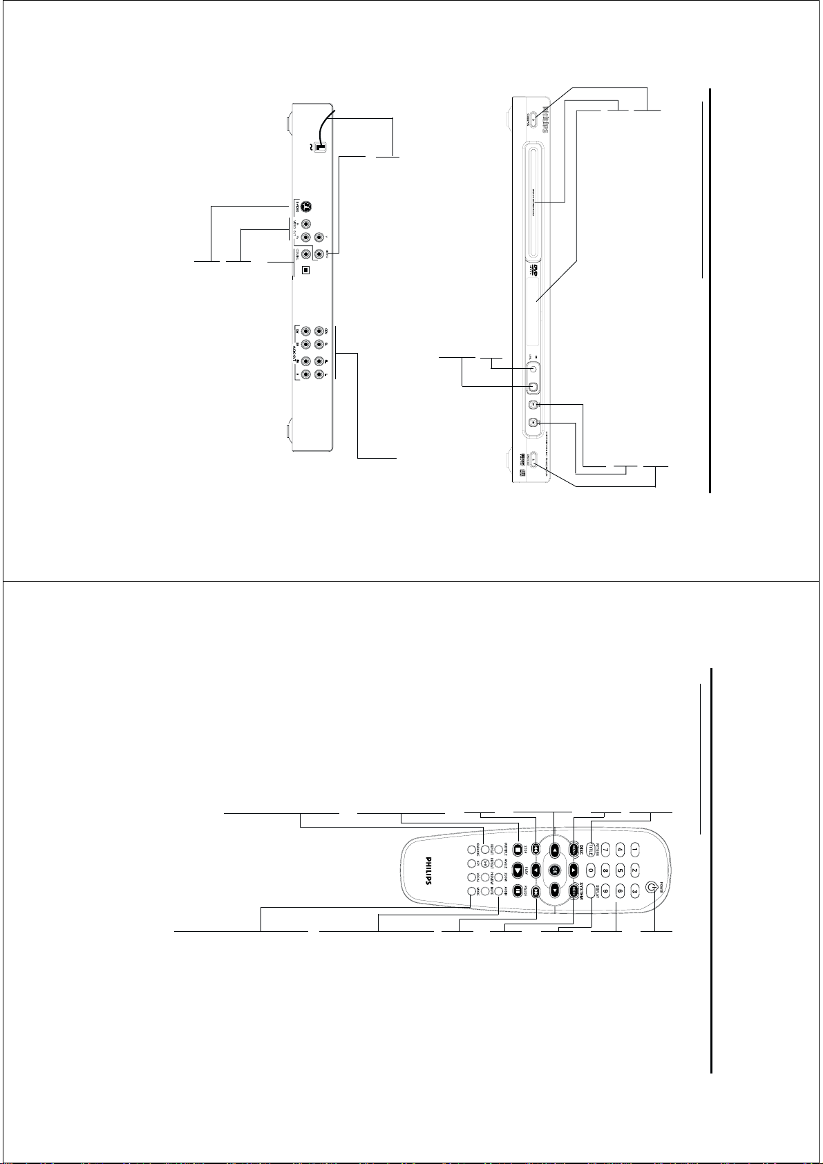
Functional overview
Front and ear Panel ...............................................5
emote Control .......................................................6
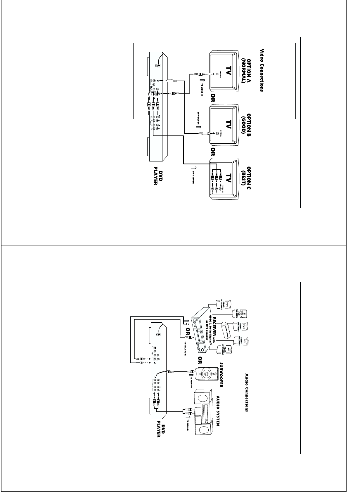
Preparation
Basic Connection ..................................................7
Connecting to a TV .............................................7
Connecting to Optional Equipment ..................8
Connecting to a Audio System ...........................8
Inserting batteries into the emote Control ..9
Using the emote Control ..................................9
Switching On .........................................................9
Smart Power On/Off............................................9
About Progressive Scan.........................................9
Operation
Basic Playback ..........................................10
General Operation ..................................10
Video control during playback ............................10
Audio control during playback ............................11
epeat .......................................................................11
epeat A-B .............................................................11
5 disc esume .........................................................11
OSD (On-Screen Display).....................................11
Zoom ........................................................................11
Special DVD Features .............................12
Playing a Title .........................................................12
Playing a Chapter ...................................................12
Camera Angle .........................................................12
Changing the Audio Language ...........................12
Subtitles ....................................................................12
Special VCD & SVCD Features .........12-13
Playback Control (PBC) ...................................12
Preview Function ...................................................13
Picture CD & MP3 CD Playback
General Operation.................................14
MP3 & JPEG Navigator...........................................14
Play Mode..................................................................14
Special JPEG Features..............................15
Function Introduction............................................15
Preview Function.....................................................15
Zoom picture ..........................................................15
Playback with multi-angles ...................................15
Scan Effect.................................................................15
Special MP3 Features...............................15
Function Introduction............................................15
Playback Speed Control ........................................15
JPEG and MP3 Simultaneous Playback....15
Contents
KARAOKE
General Operation of Karaoke .........................16
General Setup of Karaoke ..................................16
Enhanced Karaoke..................................................16
Setup menu
Basic operation ........................................17
General Setup menu ...............................17
OSD language .........................................................17
Program ..............................................................17-18
Disc Lock .................................................................18
Display DIM.............................................................18
Screen Saver ............................................................18
Analog Audio Setup menu ...................19
DOWNMIX.............................................................19
D. .C .......................................................................19
Front Speaker...........................................................19
Center Speaker.......................................................19
ear Speaker...........................................................19
Subwoofer.................................................................19
Test Speaker............................................................19
Channel Delay.........................................................19
Sound Mode............................................................19
everb Mode............................................................20
Digital Audio Setup menu.....................20
Digital Output..........................................................20
LPCM Output..........................................................20
Video Setup menu.... ...............................21
TV Type ...................................................................21
TV Display ...............................................................21
Closed Captions.....................................................21
Progressive...............................................................21
Smart Picture ..........................................22
Color Setting......................................................22-23
Preference Setup menu ..........................23
Audio language ......................................................23
Subtitle language ...................................................24
Disc Menu language ..............................................24
Password ..................................................................24
Parental Control ....................................................25
Default Setup...........................................................25
MP3/JPEG Navigator ............................................25
Specifications
Specifications ...........................................................26
Maintenance
Maintenance ........................................................ 28
Troubleshooting
Troubleshooting ....................................................29
Language Code
Language Code ................................................30-31
4
Thank you for purchasing this Philips DVD player.
This Owner’s Manual explains the basic operation
of this DVD player.
Environmental Information
All unnecessary packaging has been omitted. We
have tried to make the packaging easy to separate
into three materials: cardboard (box), polystyrene
foam (buffer) and polyethylene (bags, protective
foam sheet).
Your DVD player consists of materials which can
be recycled and reused if disassembled by a
specialized company. Please observe the local
regulations regarding the disposal of packaging
materials, exhausted batteries and old e uipment.
Supplied accessories
– DVD-Video player
– Remote control with Batteries
– Audio/Video cables
– Owner’s Manual
Safety Information
●Before operating the DVD player, check that the
operating voltage indicated on the typeplate is
identical with the voltage of your local power
supply. If not, please consult your dealer.
●Place the DVD player on a flat, hard and stable
surface.
●There must be sufficient room in front of the
player for the drawer to be opened.
●In a cabinet, allow about 2.5cm (1 inch) of free
space all around the player for ade uate
ventilation.
●Do not expose your player to extremes of
temperature or humidity
●If the DVD player is brought directly from a cold
to a warm location, or is placed in a very damp
room, moisture may condense on the lens of the
disc unit inside the DVD player. Should this occur,
the DVD player would not operate normally.
Leave the power on for about one hour with no
disc in the DVD player until normal playback is
possible.
●The mechanical parts of the set contain self-
lubricating bearings and must not be oiled or
lubricated.
●The ventilation should not be impeded by
covering the ventilation openings with items, such
as newspapers, table-cloths, curtains, etc.
●No naked flame sources, such as lighted candles,
should be placed on the apparatus.
●The apparatus shall not be exposed to dripping
or splashing and no objects filled with li uids, such
as vases, shall be placed on the apparatus.
●When the DVD player is switched to Standby
mode, it is still consuming some power. To
disconnect the system from the power supply
completely, remove the AC power plug from the
wall socket.
Symbols Used in this Booklet
The below symbols appear in some headings and
notes with the following meanings:
Helpful Hints!
●
Some discs limit certain functions during
playback (eg fast forward is not working at
the beginning of certain discs). This is
nomal behaviour because the disc
determines the way in which you can
interact with its content.
Introduction
www.freeservicemanuals.info
It`s Free
5
Functional Overview
Front and Rear Panels
Caution: Do not touch the inner pins of the sockets on the rear panel. Electrostatic
discharge may cause permanent damage to the unit.
OPTICAL
Mains Cord
– connect to power outlet
Video out (CVBS
– connect to a TV with CVBS inputs
AUDIO OUT
– connect to AUDIO inputs of an
amplifier, receiver or stereo system
Video out (S-Video
– connect to a TV with S-Video inputs
Coaxial & Optical output
– connect to a receiver, amplifier, or stereo system with
coaxial or optical digital audio inputs
STANDBY-ON
– switches DVD ON or to standby-on mode
Disc Tray
DISPLAY
– shows the current status of the player
/ OPEN/CLOSE
– opens/closes the disc tray
9 STOP
– stops playback
B PLAY
– starts/interrupts playback
Video out (Y Pb Pr
– connect to a TV with component video inputs
MIC
– MIC socket for karaoke
LEVEL
– MIC volume control for karaoke
(push and rotate the knob to adjust)
6
Functional Overview
Remote Control
Note
Press “STOP” for about 2 seconds to
OPEN or CLOSE disc tray.
RETURN / TITLE
– go back to previous menu /
show title menu
DISC MENU
– access menu of a DVD disc
/switch PBC on/off for VCD disc
1 2 3 4
– select an item in the menu/
fast forward/backward, slow
forward/backward
OK
– acknowledge menu selection
S
– go to a previous chapter or
track
STOP ( 9
– stops playback
PLAY ( B
– starts playback
PAUSE ( ;
– pause playback temporarily /
frame-by-frame playback
REPEAT
– repeat chapter, track, title, disc
REPEAT (A-B
– repeat a specific segment
PREVIEW
– Preview the content of a track
or whole disc
MUTE
– Disable or enable sound output
POWER B
– switches DVD ON or to
standby-on mode
0-9 numerical key pad
– select numbered items in a
menu
DISPLAY
– display information on TV
screen during playback
SYSTEM MENU
– access or exit player’s system
menu
T
– go to next chapter or track
SUBTITLE
– subtitle language selector
/switch off subtitle
ANGLE
– select DVD camera angle
ZOOM
– change the size of image
AUDIO
– audio language selector
KARAOKE
– display Karaoke menu to set
MIC on or off
KEY
– display Karaoke menu to set
key control
VOCAL
– choose audio channels or
karaoke methods
MODE
– display karaoke menu
www.freeservicemanuals.info
It`s Free
7
Preparation
OPTICAL
Basic Connections
●Please refer to the instruction books of your TV,
VCR, Stereo System or other devices as
necessary to make the best connections.
●Make one of the following connections,
depending on the capabilities of your existing
e uipment.
The following guidelines are options for the best
picture and sound uality available on your DVD
player.
Connecting to a TV
If your TV has a CVBS Video input
connector,
0 Connect the CVBS VIDEO OUT jack on the DVD
player to the corresponding CVBS VIDEO IN jack
on your TV (cable supplied).
If your TV has a S-Video input connector,
0 Connect the S-Video OUT jack on the DVD
player to the corresponding S-Video IN jack on
your TV (not supplied).
If your TV has a Component video
(Y/Pb/Prinput connector,
0 Connect the Y/Pb/Pr VIDEO OUT on the DVD
player to the corresponding connector on the TV
using the component video cable (not supplied).
Warning!
– Never make or change connections with
the power switched on.
– Connect the DVD player directly to your
TV, instead of eg. a VCR, to avoid
distortion because DVD video discs are
copy protected.
– Do not connect the DVD player AUDIO
OUT to PHONO IN of your player.
8
Preparation
TO OPTICAL IN
OPTICAL
Connecting to a Audio System
1You can also listen to the sound of audio CDs and
DVD video discs by connecting to an optional
stereo systems.
2Connect the Left and Right AUDIO OUT on the
DVD player to the Left and Right AUDIO IN on
the stereo systems.
Sound
1Digital audio connections provide the clearest
sound. Connect DVD player’s COAXIAL
DIGITAL AUDIO OUT to your amplifier or
receiver.
2If digital connections are not possible, connect
the DVD player’s red and white AUDIO OUT
jacks to the left and right AUDIO IN jacks on
your amplifier, receiver, stereo or TV.
Connecting to Optional
Equipment
●A digital component with a built-in MPEG 2,
Dolby Digital™ or DTS decoder allows you to
enjoy the surround sound while producing the
effect of being in a movie theater or a concert
hall.
If your receiver has a Dolby Digital™,
MPEG 2 or DTS decoder,
Connect to A/V receiver with digital
coaxial cable or optical cable
● Connect the DIGITAL COAXIAL AUDIO OUT
jack of the DVD player to the corresponding
input jack on the receiver using the normal audio
or video cable supplied.
Connecting to a multi-channel A/
V receiver with 6 channels
AUDIO OUT connectors
● A multi-channel decoder enables playback of
DVDs recorded in multi-channel surround
without the need of optional decoder. Connect
the audio out jacks to the corresponding jacks of
your A/V receiver with six cables. In the ANALOG
AUDIO SETUP menu, set DOWNMIX to OFF
and enable the 6-channel analog audio output by
the instructions introduced in the chapter [ Setup
Menu ].
– To set the audio format of the current D D in
the Setup Menu, refer to the chapter [ Setup
Menu].
www.freeservicemanuals.info
It`s Free