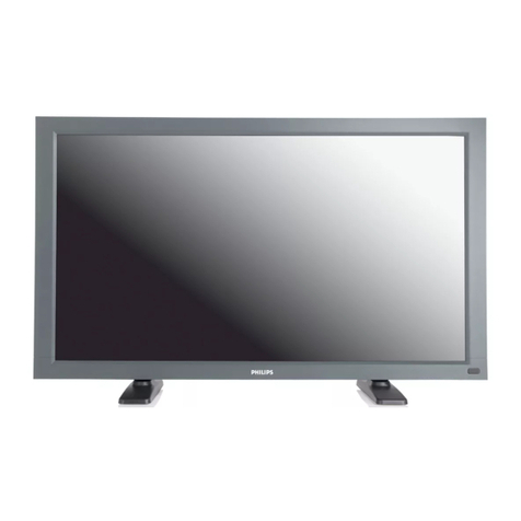
Philips PS32FHDER User manual

User Guide
32” FHD Color LCD Monitor
PS32FHDER

Barco NV
Beneluxpark 21, 8500 Kortrijk, Belgium
Phone: +32 56.23.32.11
Fax: +32 56.26.22.62
Support: www.barco.com/en/support
Visit us at the web: www.barco.com
Registered address: Barco NV
President Kennedypark 35, 8500 Kortrijk, Belgium
Phone: +32 56.23.32.11
Fax: +32 56.26.22.62
Support: www.barco.com/en/support
Visit us at the web: www.barco.com
Printed in Italy

Table of contents
TABLE OF CONTENTS
1. Welcome! .......................................................................................... 3
1.1 What’s in the box.............................................................................................. 3
1.2 Product overview.............................................................................................. 3
2. Monitor installation .............................................................................. 5
2.1 Installation procedure......................................................................................... 5
3. Daily operation ................................................................................... 9
3.1 On/Off switching............................................................................................... 9
3.2 Status LED..................................................................................................... 9
3.3 OSD menu use................................................................................................ 9
3.4 Brightness adjustment........................................................................................10
4. Advanced operation ............................................................................. 11
4.1 Monitor info ....................................................................................................12
4.2 Image source selection.......................................................................................12
4.3 Aspect ratio....................................................................................................13
4.4 Color temperature.............................................................................................13
4.5 Display function ...............................................................................................14
4.6 OSD menu position...........................................................................................15
4.7 OSD menu time-out...........................................................................................15
4.8 OSD lock.......................................................................................................16
4.9 Factory reset...................................................................................................16
4.10 Power over DVI ...............................................................................................17
4.11 +5 VDC power output.........................................................................................18
5. Cleaning your display ........................................................................... 19
5.1 Cleaning instructions .........................................................................................19
6. Important information ........................................................................... 21
6.1 Safety information.............................................................................................21
6.2 Environmental information ...................................................................................23
6.3 Biological hazard and returns................................................................................25
6.4 Regulatory information .......................................................................................25
6.5 EMC notice ....................................................................................................26
6.6 Explanation of symbols.......................................................................................29
6.7 Legal disclaimer...............................................................................................32
6.8 Technical specifications ......................................................................................32
K5902107 (451920611682) PS32FHDER 20/03/2018 1

Table of contents
2K5902107 (451920611682) PS32FHDER 20/03/2018

1. Welcome!
1. WELCOME!
Introduction
The PS32FHDER monitor is a 32” color LCD monitor to be used in a system for diagnostic and interven-
tional X-ray applications.
Type of equipment: stationary (on a stable mechanical array structure)
Intended location: inside of patient area
The monitor has not applied parts, but the front side of the LCD panel and the plastic enclosure have been
treated as applied part because considered accidentally touchable by the patient for a time <1 minute. The
maximum temperature of these parts is about 55 °C when the ambient temperature is 40 °C.
CAUTION:Read all the important safety information before installing and operating your
monitor. Please refer to the dedicated chapter in this user guide.
1.1 What’s in the box
Overview
The monitor comes with:
• this user guide
Keep your original packaging. It is designed for this monitor and is the ideal protection
during transport and storage.
1.2 Product overview
Front
1
3
2
4
1
3
2
4
Image 1-1
K5902107 (451920611682) PS32FHDER 20/03/2018 3

1. Welcome!
1Status LED 2Up / Brightness increase key
3Menu / Enter key 4Down / Brightness decrease key
Rear
1
2
Image 1-2
1VESA mounting fixation points (VESA 100
mm) 2Cable cover
Connections
21 4 5 6 73
Image 1-3
1100 - 240 VAC mains power input (IEC C14) 2DVI 1 Single Link input
3DisplayPort 1.1 input 4DVI 2 Single Link input
5+5 VDC, 500 mA power output 6USB-B 2.0 upstream connector
7USB-A 2.0 downstream connector
4K5902107 (451920611682) PS32FHDER 20/03/2018

2. Monitor installation
2. MONITOR INSTALLATION
WARNING:Sufficient expertise is required to install this equipment. All devices and
complete setup must be tested before taking into operation.
WARNING:When the display is assembled in the medical system, take care of the fixa-
tion of all cables, to avoid unwanted detachment.
WARNING:The monitor is not intended to be sterilized.
2.1 Installation procedure
Remove cable cover
To get access to the connectors, the cable cover should be removed.
1. Grab the middle bottom of the cable cover and pull it away from the monitor.
Image 2-1
Earth monitor
1. Optionally: For additional grounding, earth the monitor by connecting the protective earth pin to a
grounded outlet by means of a wire with at minimum AWG18 size (according to national Regulation re-
quirements regarding maximum admitted cable length). Use the included M4 screw to attach the wire
to the protective earth pin.
M4
Image 2-2
K5902107 (451920611682) PS32FHDER 20/03/2018 5

2. Monitor installation
Connect signal and power cables
1. Connect one or more video source(s) to the corresponding video inputs of the monitor. Use the appro-
priate video cable(s) to do this.
2. Connect the USB upstream connector to a USB host if you want to make use of any of the monitor USB
downstream connectors (e.g. to connect a keyboard, mouse or other peripheral).
3. Connect the mains power input to a grounded power outlet.
3 2
MAIN INPUT DVI2DVI1 5V USB-B USB-ADP
1
Image 2-3
Route cables
1. Route all cables trough the provided cable routing channel at the back of the monitor. Use the cable
straps at the inside of the connector compartment to fix the cables.
Image 2-4
Reattach cable cover
1. Slide the 4 position clips on top of the cable cover in the matching fixation holes at the back of the
monitor.
2. Attach the cable cover by pushing the bottom into the monitor until you hear a “click” sound at both
ends of the cover.
6K5902107 (451920611682) PS32FHDER 20/03/2018

2. Monitor installation
1
1 1
1
22
“Click!”
“Click!”
Image 2-5
VESA mount installation
1. Attach the monitor in landscape position to a 100 mm VESA mounting bracket by making use of 4 M4
screws. Mounting in portrait position is not supported.
Caution: The 4 screws should be selected according to the thickness of the VESA plate. Please con-
sider that the maximum length of the available thread for the screws inside the monitor is 6
mm and that the unthreaded distance to the outer surface of the plastic back cover is 7.8 mm.
Caution: Use an arm that is in compliance with VESA requirements.
Caution: Use an arm according to clause 9.8 of IEC 60601-1, considering that the product weight is
11.5 kg.
Image 2-6
K5902107 (451920611682) PS32FHDER 20/03/2018 7

2. Monitor installation
8K5902107 (451920611682) PS32FHDER 20/03/2018

3. Daily operation
3. DAILY OPERATION
3.1 On/Off switching
About
The PS32FHDER monitor automatically turns on as soon as the power cord is connected to the mains
plug.
The monitor requires at maximum 30 seconds to power-up.
3.2 Status LED
About
During start-up, the monitor performs a self-test and sync-test before going into normal operation mode.
Depending on the test results, the status LED at the left side of the monitor will have a different color and
lighting duration. Below is an overview of the possible status LED modes:
Status Color Description
Monitor OFFOFF N/A
Monitor ON, Video sync OK,
default OSD settings
ON ORANGE, static Monitor ON, powering on
ON ORANGE, blinking Monitor ON, powering on, self-test
ON
ON RED, static Monitor ON, MAX brightness ON
ON RED, blinking Monitor ON, self-test FAILED
ON GREEN, static Monitor ON, Video sync OK,
settings different from default
brightness
ON GREEN, blinking Monitor ON, No video sync
3.3 OSD menu use
To open the OSD menu
• If the OSD is locked (default setting), first press and hold both the and keys for approximately
3 seconds, until a pop up warns you that the OSD has been unlocked for about 20 sec. Afterwards,
press the key to enter the OSD main menu.
Or,
• If the OSD is not locked, press the key during normal operation.
As a result, the OSD main menu comes up in the right bottom part of the screen. If no further actions are
taken within the following 15 seconds, the OSD menu will disappear and lock again if enabled.
K5902107 (451920611682) PS32FHDER 20/03/2018 9

3. Daily operation
The OSD menu time-out value can be adjusted in the OSD menu (OSD menu time-out).
The OSD lock function can be enabled or disabled in the OSD menu (OSD lock).
The OSD menu position can be adjusted in the OSD menu (OSD menu position).
To navigate through the OSD menus
•Usetheor key to scroll up or down through the different menu pages, change values or make
selections.
• Togointoasubmenuorconfirm adjustments and selections, use the key.
• To exit a menu or return to the previous menu level, scroll the top level item of the current menu, then
press the key.
3.4 Brightness adjustment
To adjust the brightness
• If the OSD is locked (default setting), first press and hold both the and keys for approximately
3 seconds, until a pop up warns you that the OSD has been unlocked for about 20 sec. Afterwards,
press the brightness increase ( )orbrightnessdecrease( ) keys to adjust the brightness as desired.
Or,
If the OSD is not locked, press the brightness increase ( ) or brightness decrease ( ) keys to adjust the
brightness as desired.
The OSD lock function can be enabled or disabled in the OSD menu (OSD lock).
To force MAX brightness ON
When brightness is at 100%, by keeping the Up / Brightness increase key ( ) pressed for at least 3
seconds, the brightness is forced to the MAX brightness mode, which adds up 20 cd/m² to the default
stabilized brightness value. Press the Menu / Enter key ( ) to exit the MAX brightness mode.
10 K5902107 (451920611682) PS32FHDER 20/03/2018

4. Advanced operation
4. ADVANCED OPERATION
OSD menu structure
Below is an overview of the PS32FHDER OSD menu structure. Detailed info about the different menus
and settings is available in the next sections.
Bottom right
Bottom left
Up right
Up left
Center
OSD Position
15 sec.
30 sec.
60 sec.
120 sec.
240 sec.
OSD Timeout
PIN 14 ON
PIN 16 ON
Off
DVI1 5V
PIN 14 ON
PIN 16 ON
Off
DVI2 5V
On
Off
OSD Lock
On
Off
5V Output
Factory Reset
Settings
Backlight operating hours
Status
12NC
Total operating hours
Timing
Firmware Version
Serial Number
Model: PSXXXHDXR
Info
Display Function
Color Temperature
Aspect Ratio
DisplayPort
DVI1
DVI2
Native
Aspect
Native
Calibrated
Full Screen
Native
DICOM 1
CAL.DICOM
TG3-PMS
Source
Image
DICOM 2
DICOM 3
DICOM 4
Image 4-1
K5902107 (451920611682) PS32FHDER 20/03/2018 11

4. Advanced operation
4.1 Monitor info
About monitor info
The monitor serial number, firmware version, operating hours, etc. are available in a dedicated section of
the OSD menu.
To retrieve info about your monitor
1. Bring up the OSD main menu.
2. Navigate to the Info menu.
Info
Image
Settings
Model
Serial Number
PSXXXHDXR
XXXXXXXXXXXXX
Firmware Version XXXXXXXXXXXXX
0
0
Valid signal
9919 322 XXXXX
Timing
Total operating hours
Backlight operating hours
Status
1920x1080@60 Hz
Image 4-2
4.2 Image source selection
About image source selection
The monitor can have multiple video inputs connected. Switching between the different inputs can be
done easily in the OSD menu.
To select the image source
1. Bring up the OSD main menu.
2. Navigate to the Image >Source menu.
3. Select one of the available input image sources.
Info
Image
Settings
Source
Aspect Ratio
Color Temperature
Display Function
DVI2
Full Screen
Calibrated
Native
Image 4-3
12 K5902107 (451920611682) PS32FHDER 20/03/2018

4. Advanced operation
4.3 Aspect ratio
About aspect ratio
Following settings are available:
•Native: Input pixel to LCD pixel mapping, no scaling, aligned to the screen center.
•Aspect: Fill the screen on largest dimension, no modification in image aspect-ratio
•Full Screen: Fill the screen, image aspect-ratio can be altered
To adjust the aspect ratio
1. Bring up the OSD main menu.
2. Navigate to the Image >Aspect ratio menu.
3. Select one of the available aspect ratios.
Info
Image
Settings
Source
Aspect Ratio
Color Temperature
Display Function
DVI2
Full Screen
Calibrated
Native
Image 4-4
4.4 Color temperature
About color temperature
This setting allows you to modify the monitor white point, used as reference for all other colors to be
displayed. The available color temperature settings for your monitor are:
•Native: The native, unmodified color temperature of the LCD panel.
•Calibrated: Corresponds to a color temperature of 6800 Kelvin (D68).
To select a color temperature
1. Bring up the OSD main menu.
2. Navigate to the Image >Color Temperature menu.
3. Select one of the available color temperature settings.
K5902107 (451920611682) PS32FHDER 20/03/2018 13

4. Advanced operation
Info
Image
Settings
Source
Aspect Ratio
Color Temperature
Display Function
DVI2
Full Screen
Calibrated
Native
Image 4-5
4.5 Display function
About display functions
Native, uncorrected panels will display all grayscale/color levels with equal luminance increments. Studies
have shown however, that in medical images certain grayscale/color parts contain more relevant informa-
tion than others. To respond to these conclusions, display functions have been defined. These functions
emphasize on these parts containing crucial information by correcting the native panel behavior.
The available display functions for your monitor are:
•Native: The native panel behavior will not be corrected
•DICOM: DICOM (Digital Imaging and Communications in Medicine) is an international standard that
was developed to improve the quality and communication of digital images in radiology. In short,
the DICOM gamma function results in more visible grayscales in the images. It is recommended to
select the DICOM gamma function for most medical viewing applications. There are 4 different DICOM
curves:
- DICOM 1: DICOM output curve suitable for an ambient light level of approximately 20 Lux.
- DICOM 2: DICOM output curve suitable for an ambient light level of approximately 80 Lux.
- DICOM 3: DICOM output curve suitable for an ambient light level of approximately 180 Lux.
- DICOM 4: DICOM output curve suitable for an ambient light level of approximately 350 Lux.
•CAL.DICOM: This DICOM gamma function allows the comparison with displays having different char-
acteristics by applying the same identical transfer curve in the range of 2:200 cd/m².
•TG3-PMS: This special gamma correction of the native grayscale of the monitor is used for compati-
bility with LCD and CRT medical monitors.
To select a display function
1. Bring up the OSD main menu.
2. Navigate to the Image >Display function menu.
3. Select one of the available display functions.
14 K5902107 (451920611682) PS32FHDER 20/03/2018

4. Advanced operation
Info
Image
Settings
Source
Aspect Ratio
Color Temperature
Display Function
DVI2
Full Screen
Calibrated
Native
Image 4-6
4.6 OSD menu position
About the OSD menu position
By default, the OSD menu comes up in the right bottom part of the screen. This position can be modified
however. There’s choice from a number of predefined positions.
To change the position of the OSD menu
1. Bring up the OSD main menu.
2. Navigate to the Settings >OSD Position menu.
3. Select one of the available OSD menu positions.
Info
Image
Settings
OSD Position
OSD Timeout
OSD Lock
Factory Reset
DVI1 5V
DVI2 5V
5V Output
Center
240 sec.
Off
Off
Off
Off
Image 4-7
4.7 OSD menu time-out
About the OSD menu time-out
By default, the OSD menu will disappear automatically after approximately 15 seconds of inactivity. This
time-out value can be adjusted to a maximum of approximately 4 minutes (240 sec.)
To adjust the OSD menu time-out value
1. Bring up the OSD main menu.
2. Navigate to the Settings >OSD Timeout menu.
3. Select one of the available time-out values.
K5902107 (451920611682) PS32FHDER 20/03/2018 15

4. Advanced operation
Info
Image
Settings
OSD Position
OSD Timeout
OSD Lock
Factory Reset
DVI1 5V
DVI2 5V
5V Output
Center
240 sec.
Off
Off
Off
Off
Image 4-8
4.8 OSD lock
About the OSD lock
This setting allows you to prevent the access to the OSD and to the brightness control when enabled.
To fully lock/unlock the OSD
1. Bring up the OSD main menu.
2. Navigate to the Settings >OSD Lock menu.
3. Select On to enable or Off to disable the OSD lock.
Info
Image
Settings
OSD Position
OSD Timeout
OSD Lock
Factory Reset
DVI1 5V
DVI2 5V
5V Output
Center
240 sec.
Off
Off
Off
Off
Image 4-9
To temporarily unlock and enter the OSD
Press and hold both the and keys for approximately 3 seconds, until a pop up warns you that the
OSD has been unlocked for about 20 sec.
4.9 Factory reset
About the factory reset
The factory reset option allows to reset all OSD menu settings to its default settings. The default settings
are described below.
Image menu:
16 K5902107 (451920611682) PS32FHDER 20/03/2018

4. Advanced operation
• Image source: DVI1
• Aspect ratio: Aspect
• Color temperature: Calibrated
• Display function: CAL. DICOM
Settings menu:
• OSD menu position: Bottom right
• OSD menu time-out: 15 sec.
• OSD lock: On
• Power (5V) over DVI1: PIN 14 ON
• Power (5V) over DVI2: PIN 14 ON
• +5 VDC power output: On
Brightness setting: 100%
To reset the OSD menu settings
1. Bring up the OSD main menu.
2. Navigate to the Settings menu.
3. Select Factory reset.
Info
Image
Settings
OSD Position
OSD Timeout
OSD Lock
Factory Reset
DVI1 5V
DVI2 5V
5V Output
Bottom right
15 sec.
On
Off
PIN 14 ON
On
Image 4-10
4.10 Power over DVI
About power on DVI
This setting allows you to select on which pin of the DVI connector(s) that the +5 VDC supply is applied,
or to completely disable the +5 VDC over DVI.
To adjust the power on DVI
1. Bring up the OSD main menu.
2. Navigate to the Settings >DVI1 5V or DVI2 5V menu.
3. Select one of the available options.
K5902107 (451920611682) PS32FHDER 20/03/2018 17

4. Advanced operation
Info
Image
Settings
OSD Position
OSD Timeout
OSD Lock
Factory Reset
DVI1 5V
DVI2 5V
5V Output
Center
240 sec.
Off
Off
Off
Off
Image 4-11
Info
Image
Settings
OSD Position
OSD Timeout
OSD Lock
Factory Reset
DVI1 5V
DVI2 5V
5V Output
Center
240 sec.
Off
Off
Off
Off
Image 4-12
4.11 +5 VDC power output
About the +5 VDC power output
The monitor features a +5 VDC power output connector that can be used to connect miscellaneous pe-
ripherals. The power on this connector can be enabled or disabled in the OSD menu.
To enable/disable the +5 VDC power output power connector
1. Bring up the OSD main menu.
2. Navigate to the Settings >5V Output menu.
3. Select On to enable or Off to disable the +5 VDC power output connector.
Info
Image
Settings
OSD Position
OSD Timeout
OSD Lock
Factory Reset
DVI1 5V
DVI2 5V
5V Output
Center
240 sec.
Off
Off
Off
Off
Image 4-13
18 K5902107 (451920611682) PS32FHDER 20/03/2018
Table of contents
Other Philips Monitor manuals

Philips
Philips D Series User manual

Philips
Philips 152B1 User manual

Philips
Philips 150B2 User manual

Philips
Philips CM8833 User manual

Philips
Philips 190V6 User manual

Philips
Philips 220V8 User manual

Philips
Philips 191V2AB User manual

Philips
Philips 246V6 User manual

Philips
Philips MWE1160T User manual

Philips
Philips 150P2M User manual

Philips
Philips 150S3H User manual

Philips
Philips 273E1 User manual

Philips
Philips 193EI User manual

Philips
Philips 17C2322ES User manual

Philips
Philips 107C62 User manual

Philips
Philips 4000 series User manual

Philips
Philips 190BW9 User manual

Philips
Philips 191TE2LB User manual

Philips
Philips 200P3G - Brilliance - 20.1" LCD Monitor User manual

Philips
Philips 190WV7 User manual