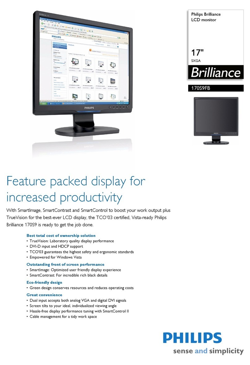
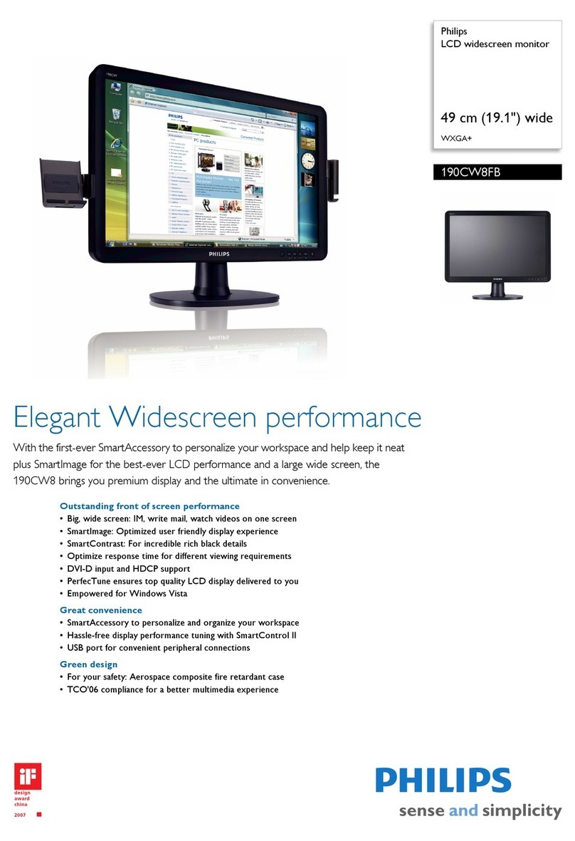
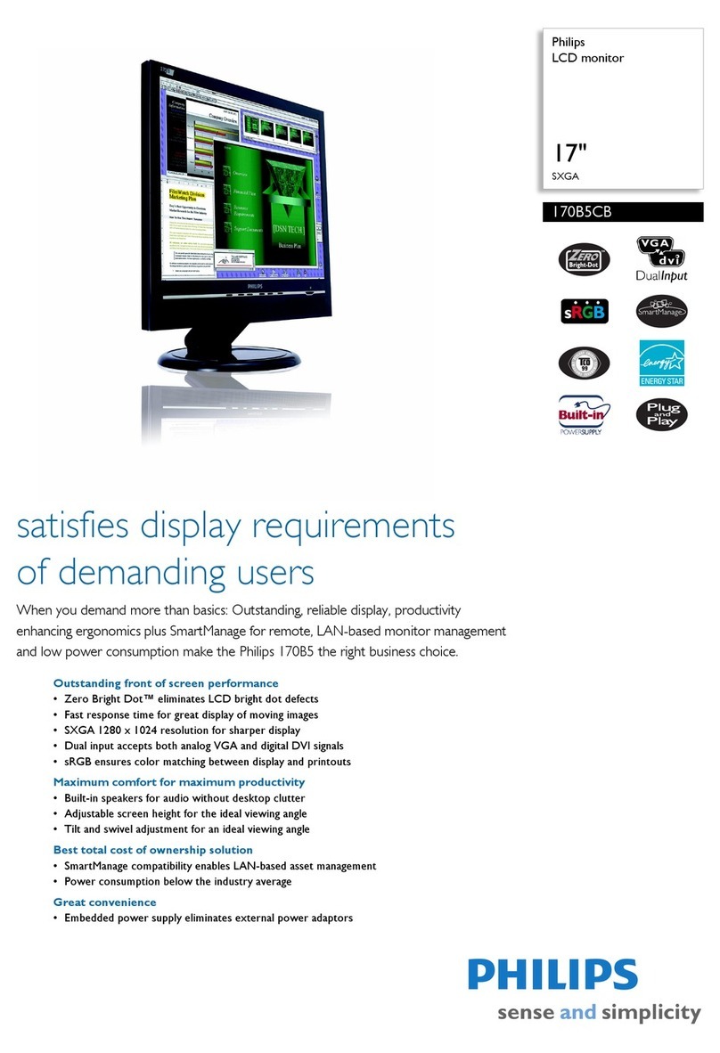
170X4
# Resolution H-Frequency Pixel rate V-Frequency Comment
1 640X350 31.5KHz 25.175 70Hz IBM VGA 10h
2 720X400 31.5KHz 28.322 70Hz IBM VGA 3h
3 640X480 37.5KHz 31.501 75Hz
4 640X480 35.0KHz 30.24 67Hz
5 640X480 31.5KHz 25.175 60Hz
6 800X600 35.2KHz 36 56Hz
7 800X600 46.9KHz 49.498 75Hz
8 800X600 37.9KHz 40 60Hz
9 832X624 49.7KHz 57.28 75Hz MAC
10 1024X768 60.0KHz 78.75 75Hz
11 1024X768 48.4KHz 65 60Hz
12 1152X870 68.7KHz 100 75Hz MAC
13 1152X900 71.8KHz 108 76Hz SUN Mode II
14 1280X1024 64.0KHz 108 60Hz
15 1280X1024 80.0KHz 135 75Hz
16 688X556 31.3KHz 27 50Hz TV-PAL
3
Technical Specifications
Technical Data
Go to cover page
LCD
Type NR. : CLAA170EA03 (CPT.)
Number of Pixels. : 1280 (H) x 1024 (V)
Physical Size. : 358.5(w)296.5(h)17(d) mm
Pixel Pitch. : 0.264 (per one triad) x 0.264 mm
Color pixel arrangement : RGB vertical stripes
Support Color. : 262k colors (RGB 6 bits data)
Display Mode. : Normally White
Backlight. : CCFL edge light system
Active area. (WXH). : 337.92 x 270.336mm (17inch diagonal)
Viewing Angle. : Vertical 140 degree, Horizontal 140 degree
(CR=10)
Contrast ratio. : 450:1
Luminance. : 300 cd/m (Typ)
Type NR. : QD17ER01 (QDI.)
Number of Pixels. : 1280 (H) x 1024 (V)
Physical Size. : 358.5(w)296.5(h)18.8(d) mm
Pixel Pitch. : 0.264 (per one triad) x 0.264 mm
Color pixel arrangement : RGB vertical stripes
Support Color. : 262k colors (RGB 6 bits data)
Display Mode. : Normally White
Backlight. : CCFL edge light system
Active area. (WXH). : 337.92 x 270.3mm (17inch diagonal)
Viewing Angle. : Vertical 140 degree, Horizontal 140 degree
(CR=10)
Contrast ratio. : 400:1
Luminance. : 260 cd/m (Typ)
Audio
Input signal levels: 500mVrms
Input signal connector: 3.5mm mini jack (lime green)
Loudspeaker: 2W+2W stereo (Impedance: 16Ohm)
Headphone connector: 3.5mm mini jack (black)
Headphone connection will mute speakers.
D-sub male with DDC-2B pin assignments.Blue connector thum
B-operated jackscrews .
Pin Assignment:
2
2
PIN No. SIGNAL
1 Red video input
2 Green video input /sync on green
3 Blue video input
4 GND
5 GND
6 Red video GND
7 Green video GND
8 Blue video GND
9 DDC +3.3V or +5V
10 Logic GND- Cable detect
11 GND
12 Serial data line (SDA)
13 H-sync / H+V
14 V-sync
15 Data clock line (SCL)
ENERGY STAR is a U.S. registered mark. AS AN ENERGY STAR
PARTNER, DELL Computer Corporation HAS DETERMINED THAT
THIS PRODUCT MEETS THE ENERGY STAR GUIDELINES FOR
ENERGY EFFICIENCY.
Power management
Main Voltage: AC 90 - 135 Vrms and 170 264 Vrms, 50/602 Hz
Power consumption: 50 watts max.
Operating < 40W(typical), standby<1W. (Without audio.)
DC power switch off < 1W. (Without audio.)
Power cord length: 1.8M
Power cord type: L style plug
Power indicator: LED (ON: green, Standby: amber)
Auto power saving: EPA, Nutek, VESA, DPMS,
Resolution Factory preset modes (16 modes)
Unit dimension / Weight
Set dimension (incl. pedestal): 399(W) * 398(H) * 197(D) mm
Net weight. : 4.7 kg
Susceptibility of display to external environment
Operating
- Temperature. : 5 to 35 degree C
- Humidity. : 80% max
- Altitude. : 0 to 12,000 feet
Storage
- Temperature. : -20 to 60 degree C
- Humidity. : 100% max (< 40)
- Altitude. : 0 to 30,000 feet
Note: recommend at 5 to 35 Degree C, Humidity less than 60 %
PIN 1 PIN 5
PIN 9
PIN 11
STATUS H-sync V-sync Video Power LED
On On On Active <40W Green LCD
Off Off Off Blanked <1W Amber LCD
DC Power off N / A <1W LED Off

