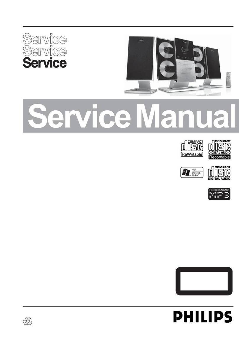
Philips MC-D370/22 User manual

CLASS 1
LASER PRODUCT
Service
Service
Service
Service
Service
MC-D370/22
©Copyright 2002 Philips Consumer Electronics B.V. Eindhoven, The Netherlands
All rights reserved. No part of this publication may be reproduced, stored in a retrieval system or
transmitted, in any form or by any means, electronic, mechanical, photocopying, or otherwise
without the prior permission of Philips.
Published by SL-ET 0229 Service AudioPrinted in The Netherlands Subject to modification
GB
3140 785 32560
DVD Receiver
Version 1.0
TABLE OF CONTENTS Page
Location of PC Boards................................................1-2
Versions Variation & Package ....................................1-2
Specifications..............................................................1-3
Measurement Setup ...................................................1-4
Service Aids ................................................................1-5
ESD & Safety Instruction............................................1-6
Preparation & Connections ........................... 1-7 to 1-12
Setting Procedure & Repair Instructions.......................2
Disassembly Instructions & Service positions ..............3
Block & Wiring Diagram ................................................4
Control Board.................................................................5
Earphone Board.............................................................6
Tuner Board ...................................................................7
Amplifier Board .............................................................. 8
Main Board ....................................................................9
Power Board ................................................................ 11
Scart Board..................................................................10
Mechanical Exploded View & Parts List......................12
ServiceManual
COMPACT
DIGITAL AUDIO

1-2
LOCATION OF PC BOARDS

1-3
SPECIFICATIONS
AMPLIFIER SECTION
Output power
- Stereo mode (DIN) ................................................ 2 x 23 W
Total Harmonic Distortion ..............10% at rated power ( kHz)
Frequency Response ........................180 Hz - 14 kHz / ±1 dB
Signal-to-Noise Ratio ..................................... > 65dB (CCIR)
Input Sensitivity ......................................................... 400 mV
TUNER SECTION
Tuning Range ..........................................FM 87.5 – 108 MHz
................................. AM (MW) 531 – 1602 kHz (9 kHz steps)
26 dB Quieting Sensitivity ....................................... FM 20 dB
26 dB Quieting Sensitivity ..................... AM (MW) 5000 mV/m
Image Rejection Radio.............................................. FM 25dB
...................................................................... AM (MW ) 28 dB
IF Rejection Ratio .................................................... FM 60 dB
....................................................................... AM (MW) 24 dB
Signal-to-Noise Ratio ............................................... FM 55 dB
....................................................................... AM (MW) 35 dB
AM Suppression Ratio ............................................. FM 30 dB
Harmonic Distortion........................................... FM Mono 3 %
.........................................................................FM Stereo 3 %
.......................................................................... AM (MW) 5 %
Frequency Response ...................FM180 Hz – 10 kHz / ±6 dB
Stereo Separation ........................................FM 26 dB (1 kHz)
Stereo Threshold................................................... FM 23.5 dB
DVD SECTION
Laser Type .......................................................Semiconductor
Disc Diameter........................................................ 12cm / 8cm
Video Decoding .......................................................... MPEG-2
Video DAC ....................................................................10 Bits
Signal System .......................................................PAL / NTSC
Video Format.............................................................4:3 / 16:9
Video S/N ..................................................... 56 dB (minimum)
Composite Video Output..................................1.0 Vp-p, 75 W
S-Video Output........................................... Y - 1.0 Vp-p, 75 W
............................................................... C - 0.286 Vp-p, 75 W
Audio DAC ..................................... Direct Digital Amplification
Frequency Response .......................4 Hz – 20 kHz (44.1 kHz)
............................................................4 Hz – 22 kHz (48 kHz)
............................................................4 Hz – 44 kHz (96 kHz)
Digital Output ................................................... SPDIF Coaxial
MISCELLANEOUS
Power Supply Rating ..................................220-240V ~ 50 Hz
Power Consumption......................................................... 80W
Dimensions (w x h x d).............. 180 mm x 132 mm x 283 mm
Weight ............................................................................ 3.7 kg
SPEAKERS
Front Speakers
System .............................................................2-way shielded
Impedance ........................................................................ 8 W
Speaker drivers .................................... 2 x 2” woofer, 1.75” tw
Dimensions (w x h x d).............. 180 mm x 132 mm x 283 mm
Weight .......................................................................... 1.75 kg
Specifications subject to change without prior notice

1-4
FM SECTION
DISC SECTION
AC MILLIVOL TME TER AUTO DISTORTION METER
OSCIL LOSCOPE
LOAD 4 OHM
AM-FM STEREO SIGNAL
GENERATOR
SIGNAL GENERATORAC
LOOP
AM LOOP ANT
DUT
INPUT OUTPUT
INPUT
OUTPUT
RL
AM SECTION
............
............
AC MILLIVOL TME TER AUTO DISTORTION METER
OSCIL LOSCOPE
LOAD 4 OHM
AM-FM STEREO SIGNAL
GENERATOR
SIGNAL GENERATORAC
DUT
INPUT OUTPUT
INPUT
OUTPUT
RL
............
............
AC MILLIVOL TME TER AUTO DISTORTION METER
OSCIL LOSCOPE
LOAD 4 OHM
DOLBY TEST METER
SIGNAL GENERATORAC
DUT
INPUT OUTPUT
INPUT
OUTPUT
............
............
AUX SECTION
.......
............
.......
............
.......
............
.......
............
AC MILLIVOL TME TER AUTO DISTORTION METER
OSCIL LOSCOPE
LOAD 4 OHM
DUT
INPUT
............
............
.......
............
.......
............
.......
............
.......
............
DVD TEST DISC
R L C SRSLSWR L C SRSLSW

1-5
Service Tools:
Universal Torx driver holder .................................4822 395 91019
Torx bit T10 150mm ...........................................4822 395 50456
Torx driver set T6-T20 .........................................4822 395 50145
Torx driver T10 extended .....................................4822 395 50423
Compact Disc:
SBC426/426A Test disc 5 + 5A ...........................4822 397 30096
SBC442 Audio Burn-in test disc 1kHz .................4822 397 30155
SBC429 Audio Signals disc .................................4822 397 30184
Dolby Pro-logic Test Disc ....................................4822 395 10216
ESD Equipment:
Anti-static table mat - large 1200x650x1.25mm ...4822 466 10953
anti-static table mat - small 600x650x1.25mm .....4822 466 10958
Anti-static wristband ............................................4822 395 10223
Connectorbox (1MΩ) ..........................................4822 395 11307
Extension cable
(to connect wristband to conn.box) ..........4822 320 11305
Connecting cable
(to connect table mat to conn.box) ...........4822 320 11306
Earth cable (to Connect product to mat or box) --4822 320 11308
Complete kit ESD3
(combining all above products) ...............4822 320 10671
Wristband tester ...................................................4822 344 13999
SERVICE AIDS
HANDLING CHIP COMPONENTS

1-6
GB
WARNING
All ICs and many other semi-conductors are
susceptible to electrostatic discharges (ESD).
Careless handling during repair can reduce life
drastically.
When repairing, make sure that you are
connected with the same potential as the mass
of the set via a wrist wrap with resistance.
Keep components and tools also at this
potential.
F
ATTENTION
Tous les IC et beaucoup d’autres
semi-conducteurs sont sensibles aux
décharges statiques (ESD).
Leur longévité pourrait être considérablement
écourtée par le fait qu’aucune précaution n’est
prise à leur manipulation.
Lors de réparations, s’assurer de bien être relié
au même potentiel que la masse de l’appareil et
enfiler le bracelet serti d’une résistance de
sécurité.
Veiller à ce que les composants ainsi que les
outils que l’on utilise soient également à ce
potentiel.
ESD
D
WARNUNG
Alle ICs und viele andere Halbleiter sind
empfindlich gegenüber elektrostatischen
Entladungen (ESD).
Unsorgfältige Behandlung im Reparaturfall kan
die Lebensdauer drastisch reduzieren.
Veranlassen Sie, dass Sie im Reparaturfall über
ein Pulsarmband mit Widerstand verbunden
sind mit dem gleichen Potential wie die Masse
des Gerätes.
Bauteile und Hilfsmittel auch auf dieses gleiche
Potential halten.
NL
WAARSCHUWING
Alle IC’s en vele andere halfgeleiders zijn
gevoelig voor electrostatische ontladingen
(ESD).
Onzorgvuldig behandelen tijdens reparatie kan
de levensduur drastisch doen verminderen.
Zorg ervoor dat u tijdens reparatie via een
polsband met weerstand verbonden bent met
hetzelfde potentiaal als de massa van het
apparaat.
Houd componenten en hulpmiddelen ook op
ditzelfde potentiaal.
I
AVVERTIMENTO
Tutti IC e parecchi semi-conduttori sono
sensibili alle scariche statiche (ESD).
La loro longevità potrebbe essere fortemente
ridatta in caso di non osservazione della più
grande cauzione alla loro manipolazione.
Durante le riparazioni occorre quindi essere
collegato allo stesso potenziale che quello della
massa dell’apparecchio tramite un braccialetto
a resistenza.
Assicurarsi che i componenti e anche gli utensili
con quali si lavora siano anche a questo
potenziale.
“Pour votre sécurité, ces documents
doivent être utilisés par des spécia-
listesagréés,seulshabilitésàréparer
votre appareil en panne”.
GB
Safety regulations require that the set be restored to its original
condition and that parts which are identical with those specified,
be used.
NL
Veiligheidsbepalingen vereisen, dat het apparaat bij reparatie in
zijn oorspronkelijke toestand wordt teruggebracht en dat onderdelen,
identiek aan de gespecificeerde, worden toegepast.
F
Les normes de sécurité exigent que l’appareil soit remis à l’état
d’origine et que soient utiliséés les piéces de rechange identiques
à celles spécifiées.
D
Bei jeder Reparatur sind die geltenden Sicherheitsvorschriften zu
beachten. Der Original zustand des Geräts darf nicht verändert werden;
für Reparaturen sind Original-Ersatzteile zu verwenden.
I
Le norme di sicurezza esigono che l’apparecchio venga rimesso
nelle condizioni originali e che siano utilizzati i pezzi di ricambio
identici a quelli specificati.
"After servicing and before returning set to customer perform a
leakage current measurement test from all exposed metal parts to
earth ground to assure no shock hazard exist. The leakage current
must not exceed 0.5mA."
CLASS 1
LASER PRODUCT
3122 110 03420
GB
Warning !
Invisible laser radiation when open.
Avoid direct exposure to beam.
S
Varning !
Osynlig laserstrålning när apparaten är öppnad och spärren
är urkopplad. Betrakta ej strålen.
SF
Varoitus !
Avatussa laitteessa ja suojalukituksen ohitettaessa olet alttiina
näkymättömälle laserisäteilylle. Älä katso säteeseen!
DK Advarse !
Usynlig laserstråling ved åbning når sikkerhedsafbrydere er
ude af funktion. Undgå udsaettelse for stråling.

3. Connecting a TV
You must connect a TV to your DVD micro system in order
to view the DVD/VCD playback.
IMPORTANT!
–There are various ways to connect the system
to a TV. You only need to make one of the best
connections, depending on the capabilities of your
TV system.
❁Use the supplied Scart cable to connect SCART OUT
jack to the corresponding SCART VIDEO IN jack on a TV.
If yourTV is not equipped with a Euroconnector, you can
select one of the following alternative connections :
Option 1
Connect the S-VIDEO OUT jack to the S-Video input
jack on the TV using a S-Video cable (not supplied).
If S-Video jack is used for video connection, the system’s
VIDEO OUT setting will need to be set accordingly. Details
are on page 11.
OR
Option 2
Connect the VIDEO OUT jack to the video input jack on
the TV using a video cable (yellow).
AC MAINS
ANTENNA
MW
FM
75
SCART OUT
VIDEO
OUT
S-VIDEO
OUT
SUBWOOFER
OUT
DIGITAL
OUT
AUX/TV
IN
LINE
OUT
L
R
SPEAKERS
(8)
L
R
+
–
+
–
AUDIO
OUT
S-VIDEO
IN
VIDEO IN
SCART IN
AUDIO
OUT
S-VIDEO
IN
VIDEOIN
SCARTIN
Helpful Hints:
–To avoid magnetic interference, do not position the front
speakers too close to your TV.
Connecting additional
equipment
IMPORTANT!
– Some DVDs are copy-protected. You cannot
record the disc through a VCR or digital recording
device.
– When making connections, make sure the
colour of cables matches the colour of jacks.
–Always refer to the owner’s manual of the other
equipment for complete connection and usage
details.
ANTENNA
MW
FM
75
SCART OUT
VIDEO
OUT
S-VIDEO
OUT
SUBWOOFER
OUT
DIGITAL
OUT
AUX
IN
LINE
OUT
L
R
SPEAKERS
(8)
L
R
+
–
+
–
DIGITAL IN
AUD IO
INPUT
AUDIO OUT
L
R
1
3
4
AUDIO IN
L
R
2
VIDEO IN
AC MAINS
1) Viewing and listening to the playback of
other equipment
Connect the system’s AUX/TV IN (R/L) jacks to the
AUDIO OUT jacks on the other audio/visual device (such
as a TV, VCR, Laser Disc player or cassette deck).
Before starting operation, press AUX/TV on the remote
in order to activate the input source.
2) Using theVCR for recording DVDs
Connect the system’s VIDEO OUT jacks to the
VIDEO IN jacks and LINE OUT (R/L) jacks to the
AUDIO IN jacks on the VCR. This will allow you to make
analogue stereo (two channel, right and left) recordings.
3) Recording (digital)
Connect the system’s DIGITAL OUT jack to the
DIGITAL IN jack on a digital recording device (such as
DTS-Digital Theatre compatible, with Dolby Digital
decoder).
Before starting operation, set the DIGITAL OUTPUT
according to the audio connection. (See page 11).
4) Connecting an active subwoofer
Connect the DVD micro system’s SUBWOOFER OUT
jack to the AUDIO INPUT jack on an active subwoofer
(not supplied).
VCR
(for example)
CD Recorder
(for example)
Te levision
(for example)
Active
subwoofer
Option 1
Option 2
IMPORTANT!
– Before connecting the AC power cord to the
wall outlet, ensure that all other connections have
been made.
–Never make or change any connections with
the power switched on.
– The type plate is located at the rear or bottom
of the system.
1. Connecting the speakers
Connect the speaker cables to the SPEAKERS terminals.
Right speaker to "R" and left speaker to "L", red (marked)
wire to "+" and black (unmarked) wire to "-". Fully
insert the stripped portion of the speaker wire into the
terminal as shown.
12
Helpful Hints:
–Ensure that the speaker cables are correctly connected.
Improper connections may damage the system due to short-
circuit.
–For optimal sound performance, use the supplied speakers.
– Do not connect more than one speaker to any one pair of
+/-speaker jacks.
– Do not connect speakers with an impedance lower than
the speakers supplied. Please refer to the SPECIFICATIONS
section of this manual.
2. Connecting antennas
MW Indoor Loop Antenna
Connect the supplied MW
(AM) loop antenna’s wires
to MW jack. Place the
antenna on a shelf or attach
it to a stand or wall.
FM Indoor Antenna
Connect the supplied FM antenna to
the FM (75 1)jack. Extend the FM
antenna and fix its ends to the wall.
For better FM stereo reception, connect an external FM
antenna using an 75 ohm coaxial cable (not supplied).
Helpful Hints:
– Adjust the position of the antennas for optimal reception.
–Position the antennas as far as possible from yourTV,VCR
or other radiation source to prevent unwanted interference.
Connections
ANTENNA
MW
FM
751
SCART OUT
VIDEO
OUT
S-VIDEO
OUT
SUBWOOFER
OUT
DIGITAL
OUT
AUX/TV
IN
LINE
OUT
L
R
SPEAKERS
(81)
L
R
+
–
+
–
AUDIO
OUT
S-VIDEO
IN
VIDEO IN
SCART IN
AUDIO
OUT
S-VIDEO
IN
VIDEOIN
SCARTIN
1
23
AC MAINS
12
Power cord
Speaker
(left)
Speaker
(right)
FM Antenna
MW Antenna
1-7

Picture Setup
SCART
TV SHAPE
Select the aspect ratio of the TV to be connected. If your
DVD is not encoded to allow you to change the aspect
ratio,TV shape cannot be changed.
4:3 PS (panscan)
Select this if you have a
conventionalTV set and your
DVD is not formatted for
widescreen viewing, use this
setting. A wide picture is
displayed on the whole TV screen with a portion
automatically cut off.
4:3 LB (letterbox)
Select this if you have a
conventionalTV set and your DVD
is formatted for widescreen
viewing, use this setting. Wide
bands is displayed on the upper
and lower portions of the TV screen.
16:9 (widescreen)
Select this if you have a
widescreen TV set, use this
setting (you must also set
your widescreen TV to “full
size”).
TV SYSTEM
Allows you to select the colour system that corresponds to
your TV.
AUTO
Select this if the connected TV is multi system, select this
mode. The output format will be in accordance with the
video signal of the disc.
NTSC
Select this if the connected TV is NTSC system, select
this mode. It will change the video signal of a PAL disc
and output to NTSC format.
PAL
Select this if the connected TV is PAL system, select this
mode. It will change the video signal of an NTSC disc
and output to PAL format.
VIDEO OUT
Set the Video Output according to your video connection.
This setting is not required if you are using the VIDEO OUT
jack (yellow) to connect the DVD micro system to your TV.
SCART
Select this if you have connected the DVD micro system
to your TV using the Scar t jack.
S-VIDEO
Select this if you have connected the DVD micro system
to your TV using S-Video jack.
SCR SAVER (Screen Saver)
OFF
Select this to disable the screen saver function.
ON
Select this if you wish to dim the TV screen when the
disc playback is stopped or paused for more than one
minute. This will prevent your display device from
becoming damaged.
Sound Setup
DIGITAL OUTPUT
Allows you to specify the type of digital output suitable for
the optional audio equipment that connected through the
DIGITAL OUT at the rear of your DVD micro system.
ALL
Select this if you have connected the digital output to a
multichannel decoder receiver.
PCM 96K
Select this if the optional audio equipment is capable of
processing digital signal input with sampling rates of 96 kHz.
PCM 48K
Select this if the optional audio equipment is incapable of
processing 96 kHz digital signal input. The signal will then
be converted to a standard signal with sampling rates of
48 kHz.
OFF
Select this to deactivate the digital output.
NIGHT MODE
Night function can also be accessed via the remote control.
OFF
Select this when you want to enjoy the surround sound
with its full dynamic range.
ON
Select this to level out the volume. High volume outputs
will be softened and low volume outputs are brought
upward to an audible level. This feature is only available
for movies with Dolby Digital mode.
Inserting batteries into the
remote control
1
Open the battery compartment.
2
Place the batteries in the
compartment with the correct
polarity as indicated by “+“ and “-“
symbols.
3
Close the cover.
CAUTION!
–Remove batteries if they are exhausted or if the
remote is not to be used for a long time.
– Do not use old and new or different types of
batteries in combination.
– Batteries contain chemical substances, so they
should be disposed off properly.
Switching on the system
1
After completing all the connections, connect the AC
power cord of the player to the power outlet.
2
Press STANDBY ON to switch on the last selected
source.
3
Adjust the SOURCE button (or press DISC,TUNER or
AUX/TV on the remote) to select the input source.
➜The selected source will be displayed.
●For viewing a DVD or VCD disc,aTV set needs to be
connected (refer to “Connections - Connecting a TV”).
Switch on the TV and set to the correct video in channel
(for example, EXT1, EXT2, AV1,AV2). Refer to your TV
instruction manual for details.
➜The default screen appears on the TV.
System Setup (DVD)
The system setup is carried out via theTV, enabling you to
customise the DVD micro system to suit your particular
requirement. If the preferred options selected are not
available on a disc, then the disc’s own preference will be
used.
IMPORTANT !
To access the System Setup menu, playback must
be stopped.
1, 5
2, 3
4
To enter System Setup menu
1
In disc mode, press SYSTEM MENU on the remote.
➜icon will be highlighted in the menu bar on the TV
screen.
2
Press 4 to activate the System Setup menu.
3
Use 34 keys to select one of the setup menu options and
press 2 to enter the menu.
4
Press OK to confirm your selection.
5
To exit the System Setup menu, press SYSTEM MENU
or OK.
Preparations
Picture Setup
Sound Setup
Language Setup
Feature Setup
1-8

Language Setup
AUDIO / SUBTITLE / DISC MENU
Select your preferred language settings for your DVD
(audio language, subtitle language and disc menus) so
that the system will automatically switch to the selected
language whenever you load a DVD. If the language
selected is not available on the disc, the original language
designated by each disc will be selected.
Features Setup
PARENTAL
Enables setting of playback limitation level. Some DVDs may
have a parental level assigned to the complete disc or to
certain scenes on the disc. The rating levels are from 1 to 8
and are country dependent. You can prohibit the playing of
certain discs that are not suitable for your children or have
certain discs played with alternative scenes.
1
Use the numeric keypad (0-9) to enter ‘1234’(default
password) when you are asked to enter the four-digit
password. You will have to enter the same code, exactly,
twice.
2
Use 34 keys to select a rating level.
3
Press OK to confirm.
Rating explanations
NO PARENTAL – It will play all discs.
8 ADULT –Mature material; should be viewed only by adults
due to graphic sexual material, violence, or language.
7 NC-17 – No children under age 17; not recommended
viewing for children under age 17.
6 PG-R – Parental Guidance - Restricted; recommended that
parents restrict children under 17 from viewing or
allow to view only when supervised by a parent or
adult guardian.
4 PG13 – Material is unsuitable for children under age 13.
3 PG – Parental Guidance suggested.
1 G – General Audience; recommended as acceptable
for viewers of all ages.
Helpful Hints:
– Some DVDs are not encoded with a rating though the
movie rating is printed on the disc jacket. The rating level
feature does not work for such discs.
– If the player’s parental level is set below 8, only discs with a
lower or equal level will play. For example, if the player is set to
5, only discs with ratings of 5, 4, 3, 2 and 1 will be played.
Higher rated scenes will not be played unless an alternative
that has the same rating or lower is available on the disc. Fo r
example, consider a disc that generally is suitable for most
audiences, and it is rated at level 2 for the most part. However,
in the middle, there are also scenes rated at 5 (not suitable for
children).
To enable playback of a higher rated disc or scene
than the level set
Go to ‘PARENTAL’and enter the four-digit cord before
resetting the rating level to a higher number.
If you forget the 4-digit code
Press Çfour times when prompted for the password
cord and the system will change back to the default
password (1234).
PASSWORD
To set a new password for the parental control or to
change the password.
CHANGE
If you are asked to enter the code for the first time, key
in ‘1234’(default password). Then enter your new four-
digit password code, twice.
MENU LANG (Menu language)
Select the language for on screen display.
DEFAULTS
RESET
Pressing 2on the remote will restore all the items in
the setup menu to the original factory setting except for
your Parental Control password.
1-9

1STANDBY ON y
–Switches between power on and Eco power standby
modes.
2ECO POWER indicator
–Lights up when the system is in Eco Power standby
mode.
3PROGRAM
–In Disc mode, to programme disc tracks.
–In Tuner mode, to programme preset radio stations.
4SOURCE
–Selects the desired source or external input source
(DISC,TUNER or AUX/TV).
5BASS / TREBLE
–Selects bass or treble sound. Use the VOLUME
control to select the desired enhancement level.
6VOLUME (VOL +-)
–Adjusts the master volume.
7PHONES
–Connect to headphones.
8TUNE 43 (S /T)
–In Disc mode, press to skip to the previous/next
chapter/track.
–In Disc mode, hold down to fast reverse/forward the
disc.
–In Tuner mode, tune to a lower or higher radio
frequency.
9STOP Ç
–Stops playing the disc or erases a programme.
0PLAY•PAUSEÉÅ
–Starts or interrupts disc playback.
!iR
–Points the remote control towards this sensor.
@Display screen
#OPEN•CLOSE 0
–Opens or closes the disc tray.
$Disc compartment
Functional Overview
Main unit and Remote control
PLAY•PAUSE STOP
TUNE
VOLUME
ECHO LEVEL MIC PHONES
iR
ECO POWER
SOURCE PROGRAM
BASS TREBLE
DVD MICRO SYSTEM
STANDBY-ON OPEN•CLOSE
DVD/MP3-CD/CD
-R/CD
-RWCOMPATIBLE
2.1 CHANNEL
2
1
3
4
5
6
8
7
9
0
!
@
#
$
%
^
&
*
9
8
0
(
)
¡
™
&
§
(•
(ª
(º
(8
(6
(
¤
(‹
⁄
£
A-B
(4
∞
24
27
%
AV (for Philips TV only)
–Selects Philips television’s AV (Audio/Video) channel.
^
DISC MENU (disc mode only)
–Enters or exits the disc contents menu.
&
SYSTEM MENU (disc mode only)
–Enters or exits the system menu bar.
*
3 4 1 2
–In Tuner mode, use 1or 2 to select a preset radio
station.
–In Disc mode, to select movement direction in disc
contents menu / system menu bar.
(
SURROUND
–Selects surround (Dolby Digital, DTS-Digital Theatre
Systems or VSS-Virtual Surround Sound) or stereo
sound effect.
)
SOUND
–Selects various sound effects : CONCERT, DRAMA,
ACTION, SCI-FI, CLASSIC, JAZZ, ROCK or DIGITAL.
¡
MODE
–During disc playback, to select various repeat modes.
–While playback stopped, to turn on/off shuffling mode.
™
REPEAT A-B
–Repeats a specific section on a disc.
£
SUBW +/-
–Adjusts the subwoofer’s sound level (for optional
active subwoofer that connected to this DVD micro
system).
REAR +/-, CENTER +/-
(Not applicable for this model)
TV VOL +/-
–Adjusts TV’s volume (Philips TV only).
§
SLEEP
–Sets the sleep timer (auto-off) function.
DIM
–Selects different levels of brightness for the display
screen.
•
NIGHT (in Dolby Digital mode only)
–Optimises the dynamics of the sound output.
ª
MUTE
–Mutes or restores the volume.
º
RESUME
–Continues disc playback after an interruption.
–When playing picture CD, to select different slide
show mode.
⁄
OK
–Exits or confirms the selection.
Numeric Keypad (0-9)
–Enters a track/title number of the disc.
–Enters a number of a preset radio station.
‹y
–Switches to standby mode.
Notes for remote control:
– First, select the source you wish to control by
pressing one of the source select keys on the remote
control (DISC orTUNER, for example).
– Then select the desired function (
É
,
S
,
T
for example).
1-10

Important notes for users in the U.K.
Mains plug
This apparatus is fitted with an approved 13 Amp plug.
To change a fuse in this type of plug proceed as follows:
1
Remove fuse cover and fuse.
2
Fix new fuse which should be a BS1362 5 Amp, A.S.T.A.
or BSI approved type.
3
Refit the fuse cover.
If the fitted plug is not suitable for your socket outlets, it
should be cut off and an appropriate plug fitted in its
place.
If the mains plug contains a fuse, this should have a value
of 5 Amp. If a plug without a fuse is used, the fuse at the
distribution board should not be greater than 5 Amp.
Note: The severed plug must be disposed of to avoid a
possible shock hazard should it be inserted into a 13 Amp
socket elsewhere.
How to connect a plug
The wires in the mains lead are coloured with the
following code: blue = neutral (N),
brown = live (L).
¶As these colours may not correspond with the colour
markings identifying the terminals in your plug, proceed
as follows:
–Connect the blue wire to the terminal marked N or
coloured black.
– Connect the brown wire to the terminal
marked L or coloured red.
– Do not connect either wire to the earth terminal in
the plug, marked E (or e) or coloured green (or green
and yellow).
Before replacing the plug cover, make certain that the
cord grip is clamped over the sheath of the lead - not
simply over the two wires.
Copyright in the U.K.
Recording and playback of material may require consent.
See Copyright Act 1956 and The Performer’s Protection
Acts 1958 to 1972.
Important Note
Norge
Typeskilt finnes på apparatens underside.
Observer: Nettbryteren er sekundert innkoplet.
Den innebygde netdelen er derfor ikke frakoplet
nettet så lenge apparatet er tilsluttet
nettkontakten.
For å redusere faren for brann eller elektrisk støt, skal
apparatet ikke utsettes for regn eller fuktighet.
Italia
DICHIARAZIONE DI CONFORMITA’
Si dichiara che l’apparecchio MCD370 Philips risponde
alle prescrizioni dell’art. 2 comma 1 del D.M. 28 Agosto
1995 n. 548.
Fatto a Eindhoven
Philips Consumer Electronics
Philips, Glaslaan 2
5616 JB Eindhoven,The Netherlands
DK
Advarsel: Usynlig laserstråling ved åbning når
sikkerhedsafbrydere er ude af funktion. Undgå
utsættelse for stråling.
Bemærk: Netafbryderen er sekundært indkoblet og
ofbryder ikke strømmen fra nettet. Den indbyggede
netdel er derfor tilsluttet til lysnettet så længe
netstikket sidder i stikkontakten.
S
Klass 1 laseraparat
Varning! Om apparaten används på annat sätt än i
denna bruksanvisning specificerats, kan användaren
utsättas för osynlig laserstrålning, som överskrider
gränsen för laserklass 1.
Observera! Stömbrytaren är sekundärt kopplad och
bryter inte strömmen från nätet. Den inbyggda
nätdelen är därför ansluten till elnätet så länge
stickproppen sitter i vägguttaget.
SF
Luokan 1 laserlaite
Varoitus! Laitteen käyttäminen muulla kuin
tässä käyttöohjeessa mainitulla tavalla saattaa
altistaa käyttäjän turvallisuusluokan 1 ylittävälle
näkymättömälle lasersäteilylle.
Oikeus muutoksiin varataan. Laite ei saa olla
alttiina tippu-ja roiskevedelle.
Huom.Toiminnanvalitsin on kytketty toisiopuolelle,
eikä se kytke laitetta irti sähköverkosta.
Sisäänrakennettu verkko-osa on kytkettynä
sähköverkkoon aina silloin, kun pistoke on
pistorasiassa.
This product complies with the radio
interference requirements of the European
Community.
CAUTION
Use of controls or adjustments or performance
of procedures other than herein may result in
hazardous radiation exposure or other unsafe
operation.
VAROITUS
Muiden kuin tässä esitettyjen toimintojen säädön
tai asetusten muutto saattaa altistaa vaaralliselle
säteil
y
lle tai muille vaarallisille toiminnoille.
1-11

Troubleshooting
WARNING!
Under no circumstances should you try to repair the system yourself, as this will invalidate the warranty. Do
not open the system as there is a risk of electric shock.
If a fault occurs, first check the points listed below before taking the system for repair. If you are unable to
solve a problem by following these hints, consult your dealer or service centre.
Problem Solution
No power. – Check if the AC power cord is properly connected.
– Press STANDBY ON on the top of the DVD micro system to turn on the power.
No picture. – Check if the TV is switched on.
– Check the video connection.
–Press DISC on the remote.
– Set your TV to the correct Video In channel. This channel is usually near channel 00. Or, you
may have a button on the TV remote control that selects Auxiliary or A/V IN channel. See
your TV owner’s manual for details. Or, change channels at the TV until you see DVD screen
on the TV.
Distorted or poor picture. – Sometimes a small amount of picture distortion may appear. This is not a malfunction.
–Clean the disc.
Completely distorted picture or – TV has a colour system standard. If the disc’s or DVD system’s colour system is different than
black/white picture. your TV’s colour system, the picture may be distorted or colourless. Set to the correct ‘TV
SYSTEM’ setting.
The aspect ratio of the screen –The aspect ratio is fixed on the DVD disc.
cannot be changed even though – Depending on the TV, it may not be possible to change the aspect ratio.
you have set the TV shape.
No sound or distorted sound. –Adjust the volume.
– Check that the speakers are connected correctly.
– Replace the speaker cables.
–Disconnect the headphones.
– The system is in pause, slow motion or fast forward/reverse mode, press PLAY to resume
normal play mode.
The micro DVD player does not –Insert a readable disc with the playback side facing down.
start playback. – Check the disc type, colour system and regional code. Check for any scratches or smudges on
the disc.
–Press SYSTEM MENU to turn off the setup menu screen.
–Cancel the parental control rating function or change the rating level.
– Moisture has condensed inside the system. Remove the disc and leave the system turned on
for about an hour.
The DVD micro system does not –Disconnect the power plug from the outlet and insert again.
respond when the buttons are pressed.
Cannot activate some features, –Multi-language sound or subtitle is not recorded on the DVD.
such as Angles, Subtitles, or –Changing the language for the sound or subtitle is prohibited on the DVD.
multi-language Audio. –The features may not be available on the disc.
Considerable noise in radio –Tune in to the correct frequency.
broadcasts. –Connect the antennas.
– Fully extend the FM wire antenna. Position for best reception and secure to a wall.
–Connect an outdoor FM or MW antenna.
– Adjust the direction and position for best reception.
–Place the antenna farther away from any equipment that may be causing the noise.
–Increase the distance between the system and yourTV or VCR.
The remote control does not –Select the correct source (DISC or TUNER, for example) before pressing the function button.
function. –Point the remote control at the remote sensor of the unit.
– Reduce the distance to the player.
–Remove any possible obstacles.
–Replace the batteries with new ones.
–Check that the batteries are loaded correctly.
The display is dark. – Press DIM again.
Low hum or buzz sound. –Place the DVD micro system as far away as possible from electrical devices that may be causing
interference.
Low bass response. – Check all speakers for correct polarity.
1-12

1) System Reset
a) Press "SYSTEM" button on R/C. TV show "SETUP"
b) Select the menu using the " " and " " button on R/C
c) Go feature setup page to do system reset
2) Region Code Change
2-1
System, Region code, Tuner, etc. setting procedure
Afterreplacement/repairoftheMPEGboard, the customer
setting and the region code may lost. Changing the Region
code will put the player back in the state which it has left the
factory.
Region Code
1USA
2EU
3AP
4Australia, NZ, Latam
5RUSSIA, INDIA
6CHINA
TV System
1NTSC
2PAL
3AUTO
Menu/ Audio Subtitle (AS) Language
1English
2English
3English
4English
AFS 003 MCD370
oem derivative
08
.region code = 1 digit
.tv system = 1 digit
."as/menu lang" = 1 digit
."AFS" = "architechture Feature Set" = 3 digits
Thisfieldisusedtodefinethearchitecture/featuressetsfor
each product.
."oem derivative" = 2 digit
This field is use to define the OEM set. This will affect the
background display.
Hence in total, reprograming will be done by way of the
remote control. It should run as below :-
a) Put the player in stop mode. No disc loaded.
b) Press the following key on remote control:
For MCD370 /22 (Europe)
<PLAY> <159> <221> <003> <08> PLAY
For MCD370 /21M (APAC)
<PLAY> <159> <331> <003> <08> PLAY
∗∗
∗∗
∗Afterthe Region Code ischanged it is necessaryto reset
the system so that the new Region Code will be fully
effective.All customer setting will be lost.
∗∗
∗∗
∗On top of the maximum number of times allowed for
changing the region code is changed to 25.
∗∗
∗∗
∗When the counter reach 25, you will not be able to further
change the code until you reset the timer by the Region
Code timer reset procedure
3) Region code change timer reset
Press below key to reset the timer :
a) In DISC source, stop mode and no disc in tray.
b) Press R/C "Play -159-PLAY" to reset timer to 25
4) Tuner area change
a)Press the "OPEN/CLOSE" button toopenthe set's door
b) Press "1" "5" "9" button by using R/C.
c) TV Show "TUNER AREA ADJUST"
d) Select the tuner area you want by using the " " and
"" button on R/C, then press "OK" to confirm. TV show
" TUNER AREA CHANGED"
If you didn't press it in five seconds, the system will remain
original status.
USA FM 87.5M 108M 100K
AM 530K 1700K 10K
APAC FM 87.5M 108M 50K
AM 531K 1602K 9K
EUROPE FM 87.5M 108M 50K
AM 531K 1602K 9K
LATAM FM 87.5M 108M 50K
AM 530K 1710K 10K
AUSTRALIA FM 87.5M 108M 50K
/ NZ AM 531K 1602K 9K
Note :-
(a) Please refer to the above different tuner area.
AREA BAND FREQUENCY (Hz) STEP(Hz)
5. Video Out Change
a) Press "SYSTEM" on R/C button
b) Select the menu using the " " and " " button on R/C
c) Go picture setup page select Video out item.
6. Password Change
a) Press "SYSTEM" on R/C button
b) Select the menu using the " " and " " button on R/C
c) Go feature setup page select "PASSWORD". TV show
"ENTER CODE". Press 4 times of "STOP" button on R/C.
d) Select "PARENTAL" "8 ADULT" on TV.
e) Enter PASSWORD to "1234"
∗∗
∗∗
∗"1234" is a default password supplied.
7. Checking on the Software version
a) Open the CD door.
b) Press "123" and "OK" on the remote control.
c) TV will show the version on screen.
8. Upgrading new software
a) Open the CD-door, then insert the CD-R program disc.
b) Close the CD-door.
c) TV will show:-
."disc loading"
."reading"
."writing" about 6 seconds.
."Done"
d) The set open the CD-door automatically.
e) The set goes to standby mode automatically.
∗∗
∗∗
∗
The latest upgraded is in version VER0527.
2-1
CAUTION !
This information is confidencial and may
not be distributed. Only a qualified service
personshouldreprogramtheRegionCode.

2-2 2-2
Check IC406 Pin16=+7v
Yes
MC-D370 REPAIR INSTRUCTIONS (1 of 2)
No Working
Power Supply
No Output
DVD AudioAudio Output
No Sound No Sound
Ear Head Phone Audio LineTunerAux in Digital LineSubwoofer Line
No Sound No Output No Output No Output No Output
Yes RE-insert and fix
the cable
F904 Bad Cause Damage
Check Back power PCBNot
No
Change F904
Bad
Ok
No Repair Between
T901 to CN907
Circuit
Yes
circuit
Work
Correct
No Check Repair
Switch Power Supply
Circuit (See B)
Check IC114 Pin3=(3.3V)
and 5V give Circuit
+5V Voltage
Yes
No Output
All Function
No Working
Repair in IC106 IC400 Circuit
RE-insert and fix
the cable
Circuit affirm Correct
No
DVD Audio
No Sound
Power Supply
No Working
No Output
No
Bad Cause Damage
No
No Output
+12V -12V Voltage
No Output
+8 V Voltage
+20V -20V Voltage
No Output
Working or Not and its conn circuti
No
F905 F906 F909
Yes
Check RL901
Check D905 D912 and
Check D901 D902 D903 D904
Check D913 D914 and
Check D911 and
its conjoint part
and its conjoint part
its conjoint part
its conjoint part
CN102 to DVD loader
Yes
DVD Serve PCB Part
Check IC106 circuit
No
its conjoint part
Check +5v
Check Repair in +12V -12V
net its conjoint part
No
Pin14 Voltage
Yes
Correct is +5V
No
Check CN907 and
its conjoint part
Correct is +12V -12V
Pin1,3,6 Voltage=+20V -20V
No Sound
Audio Output
Yes
Yes
their Voltage
Cable loose or bad INT
Yes
No
Check Repair in Check Repair Between
No
loose or bad INT
IC406 to JK401 Circuit
Yes
No Sound
Aux in
No
Check +7v and -7v
affirm Correct
Pin7=-7v give Circuit
BC DEFGHI J
MAIN UNIT REPAIR CHART
A
No Working
All Function
5V if Right
Check power pcb CN907 16pin
Check Repair
Control PCB IC206
Check All Voltage 3.3V
Working or Not
Panel stand LED show
All cable is loose
Check All System
or bad INT
Check IC902 IC903 Pin3=(5V)
B
All Voltage
Check F904
A
Check IC106 IC400
Check CN706 and
D
Check RL901
Check F902 F903 F9041
Check IC400
C
Check IC501
Check IC403,IC404,IC405,
E
Check JK401

2-3 2-3
Check IC152 Data From
MC-D370 REPAIR INSTRUCTIONS (2 of 2)
+5v Supply Circuit
No Check
Pin41 Circuit
JK401 to IC106
Check Between
Check
OK
OK
IC106 Circuit
J
At DVD mode
Check Q408 "C" =+5v
Digital Line
No Output
Circuit
Check Q401"E" Mute
Yes
and around Part Circuit
Check IC402
Yes
Subwoofer Line
No Output
if being signal
Check IC402 Pin6
No
I
Check Q400 and Q401
Q404,Q405 and Q402
Check
H
Q402"E" MUTE Circuit
OK
OK
Check
Check Between
C415 C414 to
to Jk401 Circuit
Audio Line
No Output
to CN500 Circuit
IC500 Pin1 and Pin7
Check Between
RE-insert and fix
the cable
Yes
RB700 Cable loose or INT
No Sound
Ear Head Phone
Check
OK
No
IC500 Circuit
G
Check Between CN500 to
to Tuner PCB circuit)
Chect main PCB of Tuner input Circuit
OK
(Between IC400 Pin2 and Pin15
No REpair Emdec section: Between
IC101 Pin21 to Pin22 circuit
IC101 Pin17 to RB101 Pin15(L-CH)
IC101 Pin16 to RB101 Pin13(R-CH)
OK OK
Check IC101 audio output
Check T105
Yes
Between EF001 to Q101/Q102 circuit
REpair FM IF section:
No FM function
Change
Q103,Q104
Check Q103,Q104
No
Yes
Q101,Q102
Check FM IF Output
Check FM IF Output
Q101,Q102
NoNo AM function Check AM IF T102/CF103
(Between EF001 Pin8 to IC152 Pin14 circuit)
B: Repair FM osc section
(Between IC101 Pin30 to IC152 Pin13 circuit)
No
A: Repair AM osc section (T003) or
Check IC152 or
VT section Circuit
No
Pin14--FM input
VT No Change
Check IC152 OSC input
Pin13--AM input
High Frequency=8.0-9.0v
LOW Frequency=1.5-2.0v
Check tuner VT From C161
OK
and around Part
Check IC108
No
Q104 Circuit
Check Q106 and
Check Repair Between
No
Q104"C"=+5v
RB101 to main pcb IC104
Yes
No Output
Tuner
Yes
Pin5/CL, Pin6/DO
RB101 Pin3/CE, Pin4/DI,
and IC104 Circuit
F
Check Q106"C"=+12v

2-4 2-4

3-1
DISASSEMBLY INSTRUCTIONS
1) Loosen the 4 screws on the left/right sides and the back
panel of the set.
- 4 screws "A" on the left and right side as shown in
Figure 1.
- 2 screws "B" on the back panel as shown in the
Figure 2 .
Dismantling of the Top Cover Assembly
3-1
Dismantling of the Front Panel from the Bottom bracket
1) Loosen2screws"E"onleft/rightsidesofthebottomcover
as shown in Figure 5.
2) Rip the lable on the bottom side and loosen 1screws "F"
as shown in Figure 6.
3) Loosen 2 screws "G" as shown in Figure 7.
4) Unplug the 2 cables "H" connect Key board and the
Amplify Board as shown in Figure 7.
5) Shift the front panel from the bottom bracket.
Figure 8
Figure 2
B
2) Shift the top cover from the bottom cover and remove all
the cables "C" that connect to the Main(Servo) PBC
board as shown in Figure 3.
Figure 1 A
Figure 3 C
Figure 4
1) Unplug all the cables fom the servo board.
2) Loosen 4 screws "D" to remove the Servo Board from
the top cover as shown in Figure 4.
Dismantling of the Main(Servo) Board
D
Figure 2
Figure 5
E
FFigure 6
GH
Figure 7
Dismantling of the Phone Board From the Front Panel
1) Loosen 2 screws "I" on the bottom cover as shown in
Figure 8.
I
Figure 9
J
Dismantling of the Key Board From the Front Panel
1) Loosen 9 screws "J" on the bottom cover as shown in
Figure 9.
K

3-23-2
Dismantling of the Amplify PCB
1) Loosen 2 screws "K" as shown in Figure 2.
2) Loosen 1screw "L" on the heatsink as shown in Figure 10.
3) Unplug the connectors "M" that connect amplify board and power board as shown in Figure 11.
4) Shift the amplify board together with back panel from the bottom cover.
Figure 10
Figure 14
Figure 11
Figure 12
N
L
O
M
Dismantling of the Scart PCB
1) Loosen 2 screws "Q" as shown in Figure 14.
2) Separate the scart board from the back panel.
Dismantling of the Tuner PCB
1) Loosen 2 screws "P" as shown in Figure 13.
2) Separate the tuner module from the back panel.
5)Loosen5screws"N"onthebackpanelasshowninFigure
12 from the back panel.
6) Loosen 3 screws "O" on the heatsink as shown in Figure
10. Remove the heatsink from the amplify board.
P
Figure 13
Q
Dismantling of the Power PCB
1) Loosen 4 screws "R" as shown in Figure 15.
2) Remove the cables connect to power board.
Dismantling of the Transformer
1) Loosen 4 screws "S" as shown in Figure 16.
2) Shift the transformer from the bracket.
R
Figure 15
S
Figure 16

4-1
BLOCK DIAGRAM
4-1
!"
"
#$%
"
&"
'
(
(
&
&
&"
&
&
&
!
"

4-2
WIRING DIAGRAM
4-2
&
Table of contents
Other Philips Stereo System manuals

Philips
Philips FW360C/25 User manual

Philips
Philips AZ1832B User manual

Philips
Philips FW-D750 User manual

Philips
Philips DCD132/51 User manual

Philips
Philips FW80/25 User manual

Philips
Philips MCD772 User manual

Philips
Philips FW-C35 User manual

Philips
Philips DCD8000/12 User manual

Philips
Philips FWM210X/78 User manual

Philips
Philips MCB275/05 User manual

Philips
Philips MCM530 User manual

Philips
Philips MCM299/55 User manual

Philips
Philips MCM 761 User manual

Philips
Philips FWC555 Operating manual

Philips
Philips FW 316C User manual

Philips
Philips BTM288 User manual

Philips
Philips FW535C/22 User manual

Philips
Philips FWC85C/37 User manual

Philips
Philips MCD135 User manual

Philips
Philips FW830C User manual