Philips DTP170- NA User manual

…………………………………………………....………………………………..….....................
…………………………………………………....………………………………..…..................
………………………
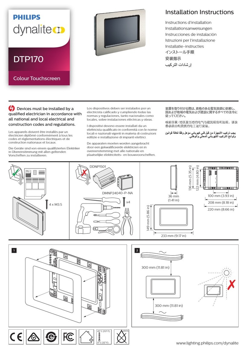
DTP170- NA
Revolution Color
Touchscreen
Installation Instructions
…………………………………………………....………………………………..…...............
………………………
Electrical Connections
Connect Data Cable in a ‘Daisy Chain’
Mounting Location
Install in a dry, well-ventilated location indoors in an office-clean area.
Data Cable Connecting Method
The recommended connecting method is to ‘daisy chain’ devices (i.e., starting
at the first device, then looping in and out of devices, with a single cable
terminating at the last device. There should not be any spurs or stubs, and
only the first and last device should terminate 1 cable, all other devices should
terminate 2 cables). Devices may be wired in any order. Data cable is Class 2
and must be separated from line (mains) conductors per NEC. A data cable
that is connected to an energized device is live. Do not cut or terminate live
data cables. For longer cable runs, the Data Cable segregation from any
Mains Cables of 12” is recommended to minimize noise coupling. If the Data
Cable has to cross over any Mains Cables, it should do so at a 90° angle.
Data Cable Termination
1. Strip off between 1” and 2-1/4” of outer jacket.
2. Cut shield (foil or braid) flush to outer jacket. DO NOT cut drain
wire.
3. Fit 1/16” heat-shrink tubing over drain wire, leaving 1/8” of wire
exposed for termination.
4. Fit 1” length of 3/8” heat-shrink tubing over the entire cable.
Position it so that 3/4” of its length is over cable jacket, and 1/4” of
its length is over loose connectors.
5. Strip 1/8” of insulation from each of the conductors.
6. Terminate conductors on the terminal block.
7. Shrink remaining heat-shrink tubing.
8. Apply the appropriate ID label to the cable at the end of the outer
heat-shrink tubing.
Cable color coding
Black: ground
Red: 24V
Blue/white pair: Blue for DATA+ White for DATA-
Recommended cable types
Belden: #1502R
Belden: #1502P
Shielded or Screened cable is recommended for DyNet networks.
UTP Cat 5 cables are acceptable under certain conditions and if installed
in conduit. See DyNet Cable Guidelines.
WARNING
This is a Class 2 device and must only be
connected to Class 2 wiring.
To reduce the risk of fire or electric shock and to avoid damage to the unit,
before installation or servicing disconnect network & device power at circuit
breakers or remove fuses. It is recommended that an electrician perform this
installation.
Do not expose this device to rain or moisture. Connect the cable shield to the
provided shield termination on a device connection port. If no shield
termination is provided on a device, connect the cable shield to equipment
grounding conductor of the supplying branch circuit(s). Installation,
programming and maintenance must be carried out by qualified personnel.
Data Cable Permanent Connections

………………………………………………....…………………………………………………………
…………………………………………………....…………………………………………………………
DTP170-NA Installation Instructions Rev B.Oct 10 2010 Specifications subject to change without notice. All rights reserved.
Dynalite, DyNet and associated logos are the registered trademarks of Philips Dynalite. Not to be reproduced without permission.
Manufactured by WMGD Pty Ltd (ABN 33 097 246 921) Unit 6, 691 Gardeners Road, Mascot, NSW 2020, Australia
Installation Steps
…………………………………………………....…………………………………………………………
This device complies with Part 15 of the FCC
Rules. Operation is subject to the following
two conditions:
(1) This device may not cause harmful
interference;
(2) This device must accept any interference
received, including interference that may
cause undesired operation.
……………………………………………....…………………………………………………………
DyNet DC Load
Audio
max. 350mA@24VDC
On-board speakers
Screen
Line out via stereo jack
TFT LCD 7 inch diagonal
Microphone
Viewing Angle: H 65˚, Vtop 60,˚ Vbottom 50˚
Data Ports
Resolution: 800 x 480 (16:9 screen ratio)
Color Depth: 16bit (65535)
Contrast: 300:1 Luminance: 280 cd/m2
Backlight: LED >50,000 hr subject to screen
saver settings and usage patterns
Power-up indicator / reset push button:
Illuminated shortly on power-up. Press and hold for 5
seconds to reset the device.
RS485 DyNet
RJ45 10/100BASE-T Ethernet
Mini USB Type B socket
USB Type A socket (keyboard/mouse)
Hardware
CPU: Intel XScale PXA310, 624MHz
Non Volatile Memory: FLASH, 512MB
Volatile Memory: SDRAM, 128MB
Touch overlay:
4 wire resistive
Compliance
RoHS, FCC, ICES Compliant (see statements)
User Page Objects
Operating Environment
Button
32º to 113ºF (0 -45° C) ambient temp
Fader
0% to 90% RH non condensing
Text box
Construction
Icon
Concealed fixings fascia, metal body and wall box
Image import
Dimensions
Operating System & Software
H 6.5” x W 8.7” x D 0.1” (exposed)
Windows CE 6.0
H5.9” x W 7.7”x D2.3” (hidden, including wall box)
Internet Explorer 6
Packed weight
Windows Media Player 9/MP3 support
DTP170-NA simulated glass fascia 3.8 lb
DTP170-NA stainless steel fascia 4.2 lb
Accessories
Wall box MK part number is 260-748-01 : 8.6 x 12.6 inches. (supplied)
Mounting Dimensions
Mounting location This device must be mounted indoors away from direct sunlight. The optimum viewing angle is 75°. Ensure that the LCD
display will be at or slightly below eye level for all users. Take this into account when deciding the mounting location.
Fixing the Device It is recommended to use wall box for dry lining / plasterboard applications. See Accessories in Product Specifications.
The display The DTP170-NA LCD display and touch membrane are sensitive to damage from sharp or hard objects. Never operate the panel
using anything other than your fingertip. Ensure there are no protrusions when fitting the panel to the wall. If cleaning is required, use a dry
cloth or soft cloth with alcohol, neutral detergent or ethanol for clearing of dirt and smudging.
Power supply The DTP170 Touchscreen is powered from the DyNet network and does not require mains voltage supply. Ensure enough
supply capacity is available from the network. For longer cable runs check voltage drop to ensure minimum 18VDC is provided across DTP170-
NA supply terminals when operating. For more information refer DyNet Cable Guidelines.
Special programming This device will only operate in basic modes until programmed. If programming is required, contact your local agent
for details. Once the data cable is connected to the device, the factory default settings will allow the panel to control all channels in all dimmers.
A reset button on the front panel allows an electronic reset.
inches
This Class A digital apparatus complies with
Canadian ICES-003
Product Specifications
…………………………………………………....…………………………………………………………
…………………………………………………....…………………………………………………………
Table of contents
Other Philips Touchscreen manuals
Popular Touchscreen manuals by other brands

Eaton
Eaton HMi Series Instruction leaflet

Tyco Electronics
Tyco Electronics ET2200L user guide

Digital Touch Systems
Digital Touch Systems DTS-5570KC user manual

Advantech
Advantech IDP31-156W Series user manual

Allo RemoteControl
Allo RemoteControl NICE Era TOUCH HSTS2FR instructions

Olivetti
Olivetti Explor 200M Service manual