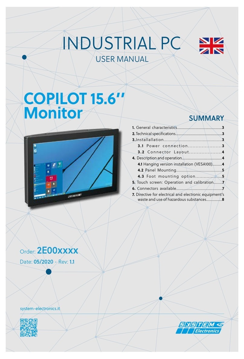
SYSTEM Electronics COPILOT Monitor 21,5" User manual

system-electronics.it
USER MANUAL
COPILOT 21,5’’
Monitor
INDUSTRIAL PC
Order Code: 2E00xxxx
Date: 05/2018 - Rev: 1.1
Summary
1. General characteristics..........................................3
2. Technical Specifications.................................................3
3. COPILOT 21.5” Monitor - Description and Operation...3
4. Installation..........................................................3
4.1 Configuration of internal connectors..................3
4.2 Installation in the hanging version (VESA100).....4
4.3 Panel mounting.....................................4
4.4 Mounting option with foot...........................5
5. Touch screen: operation and calibration...............6
5.1 Touch screen calibration...........................6
5.2 Default settings of the touch parameters.....6
6. Configuration and Menu..........................................6
7. Available connectors..........................................7
7.1 RGB, TMSD (DVI) analog signal input.........7
7.2 VGA: Analog RGB Input Connector...............8
7.3 USB connection for touch-screen............8
7.4 IEC320-C13 power plug.............8
7.5 24V power supply.............................................8
8. Several options that can be ordered.......................................8
9. Waste Electrical and Electronic Equipment Directi-
ve and use of hazardous substances................9

pag.
2
Industrial PC - MONITOR COPILOT 21,5"
Order Code 2E000xxxMay 2018 - Rev. 1.1
Revision History Pages
Rev. 1.0 Drafting 8
Rev. 1.1 Updating 9
SYSTEM CERAMICS s.p.a. Div. Electronics
via Ghiarola Vecchia, 73
41042 Fiorano (MO) - Italy
tel. 0536/836111 - fax 0536/830901
www.system-group.it
e-mail: [email protected]
This product meets the EMC protection re-
quirements of Directive 2014/30/ EC (ex
89/336 EEC) and subsequent amendments.
SYSTEM Ceramics S.p.A - Div. Electronics reserves
the right to make changes of any kind to the technical
specications at any time and without notice. The in-
formation contained in this documentation is believed
to be correct and reliable. The reproduction, even if
partial, of the content of this catalog, is allowed only
with the authorization of SYSTEM Ceramics S.p.A -
Div. Electronics
This manual applies to the following product codes:
2E000208 MONITOR COPILOT 21.5" FULL-HD TOUCH PCAP USB 220V FLUSH MOUNTED
2E000209 MONITOR COPILOT 21.5" FULL-HD TOUCH PCAP USB 220V HANGING MONITOR
2E000939 COPILOT MONITOR 21.5" FULLHD TOUCH 24V WALL UNIT

pag.
3
Industrial PC - MONITOR COPILOT 21,5"
Order Code 2E000xxxMay 2018 - Rev. 1.1
1. General features
The Copilot 21.5'' Monitor is the System Electronics
operator panel that oers performance and performance
for all supervisory and on-board machine applications,
with an innovative and robust design and mechanically
reliable.
Made of stainless steel, resistant to dust and liquids,
the Copilot 21.5'' Monitor is a solution that can be
connected to any existing PC in order to integrate the
operator interface with the machine.
The 1920x1080 FullHD graphic display allows the di-
splay of high resolution images and movies; it is equip-
ped with user adjustable LED backlighting.
The multi-touch touch screen with up to 10 simultane-
ous touches, and scratch-resistant, allows for operator
interaction with simple gestures.
2. Technical
Specications
LCD:
Measure/Model: 21,5’’ TFT Color LCD
Maximum resolution: 1920 x 1080 FullHD
Brightness: 300 cd/m2
Angle of eld: ±89° H, ±89° V
Touch Screen:
PCAP - up to 10 simultaneous touches
Guaranteed operation with gloves
Input/Output port:
USB type B for touch screen connection
Video input: DVI/VGA
Power supply: 220VAc/24Vdc
Temperature: 0°C +50°C (Max +60°C cooled version)
Assembly:Arm / Panel mounting
Physical characteristics:
Weight: Max 10 Kg
Size: 545(W) x 335(H) x 85(D) mm
Protection: IP67 - Made of stainless steel
Graphic resolutions supported:
3. Monitor COPILOT
21,5" -
Description and
operation
The Copilot 21.5'' Monitor turns on automatically when
the input power is present.
During installation, connect the USB port of the monitor
to a free port on your PC. The cable to be used must
have a USB type B connector on the side of the monitor;
also connect the video cable by attaching its fasteners
to the connector of the video card
It is recommended that the lower steel door of the
monitor be removed to connect the cables that will be
routed through the hole provided for attaching the VESA
support arm.
Power up the monitor only when all wiring is in place.
On the upper side the metal door covers the control
panel which allows ne adjustment of parameters such
as brightness, contrast, etc.
All parameters have already been optimized during the
test phase of the monitor, but can be customized accor-
ding to the dierent applications.
It is advisable to protect the 220Vac power supply line
by means of a T2A/250V fuse.
4. Installation
4.1 Configuration of internal
connectors
- Remove the 6 xing screws M5 of the Monitor Copilot
21.5'' that cover the upper and lower doors, taking care
to keep the gaskets placed in the screws themselves and
inside the mechanics, to be able to reassemble them
later in the same position.
- Typically all connecting cables are connected from the
bottom of the Monitor: removing the top door can make
it easier to insert the cables, allowing you to control
their insertion.
- Close the covers taking care to reposition the insu-
lating gaskets and screw O-rings (for models with IP67
protection).
640*350@70Hz 640*400@70Hz
640*480@60Hz 640*480@72Hz
640*480@75Hz 720*400@70Hz
800*600@56Hz 800*600@60Hz
800*600@72Hz 800*600@75Hz
1024*768@60Hz 1024*768@70Hz
1024*768@75Hz 1280*720@60Hz
1280*768@60Hz 1280*1024@60Hz
1280*1024@75Hz 1360*768@60Hz
1440*1050@60Hz 1600*1200@60Hz
1920*1080@60Hz 1920*1200@60Hz
The recommended resolution 1920x1080 allows you to
exactly match the input image to the resolution of the
LCD display, without scaling.
Maximum distance supported: 5 meters
(Optional the possibility to extend the functionality
of the Monitor and Touch up to 50 meters)

pag.
4
Industrial PC - MONITOR COPILOT 21,5"
Order Code 2E000xxxMay 2018 - Rev. 1.1
4.2 Installation in the hanging
version (VESA100)
To properly mount the Copilot 21.5" Monitor in the
VESA100 arm-mounted version follow the instructions
below:
- Remove the Copilot 21.5" Monitor from its
packaging and place it on a at surface free of objects,
placing a soft cloth on the table itself to avoid scratching
the glass during installation.
- Place the Copilot 21.5" Monitor with the glass
facing the table. Avoid even momentarily placing the
terminal in a vertical position or slightly leaning against
the mechanism to avoid damage due to the unstable
position.
- Place the cables that will be connected to the
Copilot 21.5" Monitor on the xing arm, making them
protrude about 30cm beyond the xing point of the arm
itself: cables that will be connected inside the PC itself.
- Remove the 6 M5 xing screws of the Monitor
Copilot 21.5" Monitor that cover the upper and lower
doors, taking care to keep the gaskets placed in the
screws themselves and inside the mechanics, in order
to reassemble them later in the same position.
- Typically all connection cables are connected
from the bottom of the Monitor: the removal of the top
door can facilitate the insertion of the cables allowing
you to control their insertion.
- Place the Monitor on the VESA arm by inserting
all cables inside from the rear center hole.
- The Copilot 21.5" Monitor can be attached
to the arm using the M6 screws provided. In case the
screws need to be replaced to t the used arm, be careful
not to exceed the length of the internal thread by more
than 8mm from the outer edge, to avoid damaging the
internal components.
- Only then connect the communication cables to
the VESA arm: USB, Ethernet, RS232 are all located on
the bottom side
4.2.1 Size of the opening for cable routing in the 21.5" Copilot
Monitor positioned on the VESA arm.
The Copilot 21.5'' Monitor can be installed in the
recessed or wall mounted version, prepared to be con-
nected to a VESA100 arm.
- Close the covers taking care to reposition the
insulating gaskets and screw O-rings (for models with
IP67 protection).
It is possible to adjust and tighten the VESA100 joint
of the Copilot 21.5'' Monitor (available as an option)
using a normal grinder key (cod. 90006195).
4.3 Panel mounting
- Drilling the panel according to the dimensions
indicated: 320 x 528
4.3.1 Panel drilling jig
- Remove the Copilot 21.5" Monitor from its
packaging and place it on a at surface free of objects,
placing a soft cloth on the table itself to avoid scratch-
ing the glass during installation. Place the Copilot 21.5"
Monitor with the glass facing the table. Avoid even mo-
mentarily placing the terminal in a vertical position or
slightly leaning against the mechanism to avoid damage
due to the unstable position.
- Remove the 6 M5 screws that secure the upper
and lower sides.
Figure 4.1.1: Bottom door connectors view.
***

pag.
5
Industrial PC - MONITOR COPILOT 21,5"
Order Code 2E000xxxMay 2018 - Rev. 1.1
Figure 4.3.2: mounting Monitor Copilot 21.5" in the recessed
version
Figure 4.3.3: Copilot 21.5" panel mounted monitor.
- Place the body of the Copilot 21.5" Monitor
in the hole in the panel, engaging it from the bottom
side. If the panel thickness is more than 1mm, remove
the lower corner corner as well and reassemble it after
placing the 21.5" Copilot Monitor inside its housing.
- Secure the Monitor using the adjustable side
blocks.
- Wire the connection cables.
- Reassemble the top and bottom side panels
using the screws provided.
Place the body of the Copilot 21.5" Monitor in the hole
in the panel, engaging it from the bottom side. If the
panel thickness is more than 1mm, remove the lower
corner corner as well and reassemble it after placing the
21.5" Copilot Monitor inside its housing.
4.4 Foot mounting option
The ground mounting accessory is available. The foot
can be xed to the oor and allows the passage of cables
inside the joint.
The oor-standing foot allows 90' rotation of the Copilot
21.5'' Monitor to view operator interfaces or images/
movies that require a portrait-oriented view.

pag.
6
Industrial PC - MONITOR COPILOT 21,5"
Order Code 2E000xxxMay 2018 - Rev. 1.1
operation and calibration
The Copilot 21.5'' Monitor has an innovative capaci-
tive backward-projected touch screen (PCAP) with 10
possible touches at the same time.
System Electronics can provide dierent settings to co-
ver the dierent needs of the operator interface: from
operation with gloves or in dirty environments to the
optimization in the precision of touch, up to the natu-
ralness of gestures with Windows (rotation, movement
and zoom with the hand).
The 21.5" Copilot Monitor is supplied already calibra-
ted and equipped with a setting that typically covers all
needs without penalizing any of them: however, there
are commands to customize the behavior according to
the specic application.
5.1 Touch-screen calibration:
The Copilot 21.5" Monitor does not normally require
calibration procedures, as it is already optimized during
production.
If there is a need to optimize touch-screen calibration,
follow the procedure below.
5. Touch-screen:
6. Conguration and
Menu:
To access the menu conguration buttons, remove the
three 3 screws on the top metal cover using an Allen key.
In the Tablet PC Settings section, press the "CALIBRATE"
button:
To test the calibration of the touch screen, touch the
crosshairs each time they appear on the screen with
one nger.
Click at random on the screen to return to the last ca-
libration.
Press ESC to exit.
Do not change the orientation of the monitor before
completing the calibration process.
5.2 Default settings of the touch
parameters:
To reset the factory settings again, select the "RESET"
button from the TABLET PC SETTING window:
NOTE
The Copilot 21.5" Monitor does not require specic dri-
vers; the native Windows drivers are used for touch-scre-
en operation.
Menu Select Down Up Led Power
Figura 6.1 Buttons scheme. Front Monitor View
The buttons are arranged according to the following
diagram:

pag.
7
Industrial PC - MONITOR COPILOT 21,5"
Order Code 2E000xxxMay 2018 - Rev. 1.1
Power: Power On/Power o: Do not use this
button to avoid keeping the monitor o even with the
incoming video signal.
Menu: Enable the menu display for congura-
tion
Select: Menu select function
The Up / Down keys allow you to change the preset
values
If you are not inside the Menu, the keys enable the
following functions:
• Select: Select VGA/DVI input video source
(auto default)
• Down: Automatic color calibration
• UP: Automatic synchronism calibration
The Menu allows you to change the following parame-
ters:
Picture
Brightness
Contrast
Sharpness
Position H
V Position
Clock
Phase
Color
Color Status Management User (User,
Warm, Normal, Cool)
Red
Green
Blue
Auto Color To Start
SETUP
Source RGB, DVI, AUTO
Factory reset To Start
Aspect (o/on)
Set ID (o/on)
Pin N. Symbol Description
1 TMDS DATA2- TMDS DATA2 Dierential
Negative Signal
2 TMDS DATA2+ TMDS DATA2 Dierential
Positive Signal
3 TMDS DATA2 Shield Shield Shield for TMDS
Channel #2
4 NC Not connected
5 NC Not connected
6 DDC Clock The Data Line for the DDC
Interface
7 DDC Data The Clock Line for the DDC
Interface
8 NC Not connected
9 TMDS DATA1- TMDS DATA1 Dierential
Negative Signal
10 TMDS DATA1+ TMDS DATA1 Dierential
Positive Signal
11 TMDS DATA1 Shield Shield for TMDS Channel
#1
12 NC Not connected
13 NC Not connected
14 +5V Power +5 Volt signal for EDID
(Un-powered Monitor)
15 GND (for +5V) Ground for +5 Volt Power
pin, Sync return
16 HPD Identify the presence of a
monitor
17 TMDS DATA0- TMDS DATA0 Dierential
Negative Signal
18 TMDS DATA0+ TMDS DATA0 Dierential
Positive Signal
19 TMDS DATA0 Shield Shield for TMDS Channel
#0
20 NC Not connected
21 NC Not connected
22 TMDS CLOCK Shield Shield for TMDS Clock
dierential Pair
23 TMDS CLOCK+ TMDS DATA0 Dierential
Positive Signal
24 TMDS CLOCK- TMDS DATA0 Dierential
Negative Signal
C1 NC Not connected
C2 NC Not connected
C3 NC Not connected
C4 NC Not connected
C5 NC Not connected
Table 7.1.1
7. Available
connectors
7.1 Signal Input Analog RGB,
TMSD (DVI)

pag.
8
Industrial PC - MONITOR COPILOT 21,5"
Order Code 2E000xxxMay 2018 - Rev. 1.1
8. The power
connector pinout is
shown below
The Copilot 21.5'' Monitor is customizable with dif-
ferent modules to adapt to the needs of the industrial
world:sostituendo la chiusura inferiore è possibile ag-
giungere pulsanti e tastiera, o entrambe.
Pin N. Symbol Description
1 Red1 Red analog input
2 Green1 Green analog input
3 Blue1 Blue analog input
4 GND Ground
5 GND Ground
6 GND Ground
7 GND Ground
8 GND Ground
9 NC Not connected
10 GND Ground
11 GND Ground
12 DSDA DDC-SDA
13 HSYNC Horizontal Sync
14 VSYNC Vertical Sync
15 DSCL Serial Clock Input
Table 7.2.1
7.3 Collegamento USB per
touch-screen
• 1 5V_USB
• 2 D-
• 3 D+
• 4 GND_USB
7.4 IEC320-C13 power plug
(for versions with integrated
power supply)
7.2 VGA: Analog RGB Input
Connector
7.5 24V power supply
(for 24V versions)
• 1 +24V
• 2 GND
• 3 PE
The power connector is placed vertically, accessible by
inserting your hand inside the bottom opening
The power connector pinout is shown below:

pag.
9
Industrial PC - MONITOR COPILOT 21,5"
Order Code 2E000xxxMay 2018 - Rev. 1.1
9. Waste Directive
Information to users pursuant to art. 13 of Legisla-
tive Decree 25 July 2005, n.151 "Implementation of
Directives 2002/95/EC, 2002/96/EC and 2003/108/
EC, relating to the reduction of the use of hazardous
substances in electrical and electronic equipment, and
waste disposal.
The crossed-out wheeled bin symbol on the
equipment or on its packaging indicates that
the product at the end of its useful life must
be collected separately from other waste.
The separate collection of this end-of-
life equipment is organized and man-
aged by the manufacturer. Users who wish to dispose
of this equipment should contact the manufactur-
er and follow the manufacturer's system to allow
separate collection of this end-of-life equipment.
Adequate separate collection for the subsequent start-
up of the discarded equipment for recycling, treat-
ment and environmentally compatible disposal helps
to avoid possible negative eects on the environment
and health and promotes the reuse and/or recycling
of the materials of which the equipment is composed.
The abusive disposal of the product by the hold-
er involves the application of the administra-
tive sanctions provided for by current legislation
Translated with www.DeepL.com/Translator (free ver-
sion).
This manual suits for next models
3
Table of contents
Other SYSTEM Electronics Touchscreen manuals
Popular Touchscreen manuals by other brands

Epson
Epson MicroTouch IC-215P-AA2 user manual

Elo TouchSystems
Elo TouchSystems B-series Quick installation guide

PenMount
PenMount Touchscreen 6000 installation guide

Elo TouchSystems
Elo TouchSystems 1919L user guide

Bosch
Bosch Solution 2000 quick start guide

Avalue Technology
Avalue Technology ARC-1200 Quick reference guide