Philips MatchLine VR 1200/39 User manual

Contents
Chapter
1 Disassembly
2 Mechanism adjustments
3 Electrical adjustments
4 Charts and diagrams
5 Parts lists
Specification:
Video recording system: Rotary 6-head helical scan system
Antenna input Signal: PAL B/G, SECAM L
Antenna: UVF/UHF 75Ωexternal antenna terminal
Video Output Channel: UHF E21-E69 (adjustable between 21-69)
75Ωunbalanced
Power requirement: AC 220V – 240V ~(AUTO) 50/60Hz
Power consumption: ON - 25 watts
OFF - 4.8 watts
SAVE MODE - 3 watts
Operating temperature: + 5°C to + 40°C
Relativehumidity: 10% to 80%
Weight: 4.7kg
Dimensions: 435(W) x 102(H) x 342(D)mm
OC120039.pm5
VR1200/39
Safety regulations require that the set be restored to its original
condition and that parts which are identical with those specified be
used.
Video Cassette Recorder VR1200/39
Published by CFC2001PJVM Videq Service Department Printed in the Netherlands © Copyright reserved Subject to modification 3103 785 20950
www.freeservicemanuals.info
3/3/2019
Digitized in Heiloo the Netherlands
Not for sale!

T120039
TABLE OF CONTENTS
Section Title Page
1. DISASSEMBLY
1.1 DISASSEMBLY FLOW CHART.............................................................................................................. 1-1
1.2 HOW TO READ THE DISASSEMBLY AND ASSEMBLY ....................................................................... 1-1
1.3 DISASSEMBLY/ASSEMBLY METHOD ................................................................................................. 1-1
1.4 SERVICE POSITION .............................................................................................................................. 1-4
1.5 MECHANISM SERVICE MODE ............................................................................................................. 1-4
1.6 JIG RCU MODE ..................................................................................................................................... 1-5
1.7 SERVICING ITEMS RELATED TO VIDEO NAVIGATION ........................................................................ 1-5
1.7 EMERGENCY DISPLAY FUNCTION ...................................................................................................... 1-6
2. MECHANISM ADJUSTMENT
2.1 BEFORE STARTING REPAIR AND ADJUSTMENT ................................................................................ 2-1
2.2 REPLACEMENT OF MAJOR PARTS ..................................................................................................... 2-6
2.3
COMPATIBILITY ADJUSTMENT .................................................................................................................... 2-16
3. ELECTRICAL ADJUSTMENT
3.1 PRECAUTION ........................................................................................................................................ 3-1
3.2 SERVO CIRCUIT ................................................................................................................................... 3-2
3.3 VIDEO CIRCUIT ..................................................................................................................................... 3-2
3.4 AUDIO CIRCUIT ..................................................................................................................................... 3-4
3.5 SYSCON CIRCUIT ................................................................................................................................. 3-4
3.6 PAL/SECAM CONVERTER CIRCUIT .................................................................................................... 3-5
4. CHARTS AND DIAGRAMS
NOTES OF SCHEMATIC DIAGRAM .............................................................................................................. 4-1
CIRCUIT BOARD NOTES ............................................................................................................................... 4-2
4.1 BOARD INTERCONNECTIONS .............................................................................................................. 4-3
4.2 MAIN (VIDEO/AUDIO) AND AUDIO ERASE SCHEMATIC DIAGRAMS .................................................. 4-5
4.3 MAIN (SYSCON) SCHEMATIC DIAGRAM ............................................................................................. 4-8
4.4 MAIN (SW.REG) SCHEMATIC DIAGRAM ............................................................................................. 4-11
4.5 MAIN (TUNER) SCHEMATIC DIAGRAM ................................................................................................ 4-13
4.6 MAIN (CONNECTION) SCHEMATIC DIAGRAM ..................................................................................... 4-15
4.7 2D DIGITAL SCHEMATIC DIAGRAM ..................................................................................................... 4-17
4.8 TERMINAL SCHEMATIC DIAGRAM ...................................................................................................... 4-19
4.9 DEMODULATOR SCHEMATIC DIAGRAM ............................................................................................. 4-21
4.10 S-SUB SCHEMATIC DIAGRAM ............................................................................................................ 4-23
4.11 DISPLAY, REC SAFETY, S-JACK AND JOG SCHEMATIC DIAGRAMS ................................................ 4-25
4.12 S-P CONVERTER SCHEMATIC DIAGRAM ........................................................................................... 4-27
4.13 SECAM SCHEMATIC DIAGRAM .......................................................................................................... 4-29
4.14 2D DIGITAL AND S-SUB CIRCUIT BOARDS ......................................................................................... 4-31
4.15 TERMINAL CIRCUIT BOARD ................................................................................................................ 4-32
4.16 MAIN CIRCUIT BOARD ......................................................................................................................... 4-33
4.17 S-P CONVERTER CIRCUIT BOARDS ................................................................................................... 4-36
4.18 DISPLAY, REC SAFETY, JACK, JOG, DEMODULATOR AND SECAM CIRCUIT BOARDS ...................4-37
4.19 REMOTE CONTROLLER SCHEMATIC DIAGRAM ................................................................................ 4-39
4.20 FDP GRID ASSIGNMENT AND ANODE CONNECTION ........................................................................ 4-40
4.21 WAVEFORMS ...................................................................................................................................... 4-41
4.22 VOLTAGE CHARTS .............................................................................................................................. 4-43
4.23 CPU PIN FUNCTION ............................................................................................................................. 4-45
4.24 SYSTEM CONTROL BLOCK DIAGRAM ............................................................................................... 4-47
4.25 VIDEO BLOCK DIAGRAM .................................................................................................................... 4-49
4.26 AUDIO BLOCK DIAGRAM .................................................................................................................... 4-53
5. PARTS LIST
5.1 PACKING AND ACCESSORY ASSEMBLY ........................................................................................... 5-1
5.2 CABINET AND CHASSIS ASSEMBLY................................................................................................... 5-2
5.3 MECHANISM ASSEMBLY .................................................................................................................... 5-3
www.freeservicemanuals.info
3/3/2019
Digitized in Heiloo the Netherlands
Not for sale!

1-1
[1] Top cover, D1 4(S1a),(S1b)
Bracket 2(S1c)
[2] Bottom cover D2 <Note 2a>
(Foot(rear)) 4(L2a)
(Foot assy) 4(L2b)
(S2a),2(S2b),4(L2c),
3(L2d)
[3] Front panel assembly D3 7(L3a), <Note 3a>
CN901(WR3a), <Note 3b>
CN3012(WR3b)
Jack board assembly 2(S3a)
Jog board assembly 2(S3b) <Note 3c>
[4] Drum assembly D4 CON1(WR4a), <Note 3a>
CN1(WR4b),
(S3a),(S3b),(S3c)
(Inertia plate) 4(L4a)
(Roller arm assy) (L4b),(P4)
(Cleaner assy) (L4c)
[5] Mechanism assembly D5 CN2001(WR5a), <Note 3a>
(S5a),(S5b),2(S5c) <Note 5a>
[6] Rec safety board D6 (L6a) <Note 6a>
assembly
Display board assembly
CN7001(WR6a), <Note 3a>
CN7191(WR6b),
2(L6b),5(L6c)
[7] S/P Conv circuit D7 CN1601(WR7b) <Note 3a>
assembly CN1602(WR7a)
2(S7c)
Main board assembly 2(S7a), (S7b)
SECTION 1
DISASSEMBLY
1.3 Disassembly/assembly method
1.1 Disassembly flow chart
This flowchart lists the disassembling steps for the cabinet
parts and P.C. boards in order to gain access to item(s) to
be serviced. When reassembling, perform the step(s) in re-
verse order. Bend, route and dress the flat cables as they
were originally laid.
1.2
How to read the disassembly and assembly
Note:
•
The bracketed ( ) WR of the connector symbol are as-
signed nos. in priority order and do not correspond to
those on the spare parts list.
(5) Adjustment information for installation
Top cover, Bracket
Bottom cover
Front panel assembly,
Jack board assembly,
Jog board assembly
Drum assembly
Mechanism assembly
Rec safety board assembly,
Display board assembly
Main board assembly
[1]
[2]
[3]
[4]
[5]
[6]
[7]
Step/
Loc No.
Part Name Fig.
No. Point Note
-----------------
(1) (2) (3) (4) (5)
Step/
Loc No.
Part Name Fig.
No. Point Note
[1] Top cover, D1
4(S1a),(S1b),3(L1a), <Note 1a>
2(SD1a),(P1a),(W1a),
CN1(WR1a),
Bracket 2(S1c)
<Example>
(1) Order of steps in Procedure
When reassembling, perform the step(s) in the reverse order.
These numbers are also used as the identification (location) No.
of parts Figures.
(2) Part name to be removed or installed.
(3) Fig. No. showing procedure or part location.
(4) Identification of part to be removed, unhooked, unlocked,
released, unplugged, unclamped or unsoldered.
P= Spring, W= Washer, S= Screw, L= Locking tab, SD= Solder,
CN**(WR**)= Remove the wire (WR**) from the connector
(CN**).
<Note 2a>
• When attaching the Bottom cover, make sure that the earth plate of
the Bottom cover is passed through the hole of the Bottom chassis
and then touches the GND (Ground) on the Main board assembly.
<Note 3a>
• Be careful not to damage the connector and wire etc. during
connection and disconnection.
When connecting the wire to the connector, be careful with the
wire direction.
<Note 3b>
• When reattaching the Front panel assembly, make sure that
the door opener “a” of the Cassette holder assembly is low-
ered in position prior to the reinstallation.
<Note 3c>
• The Jog board assembly can be removed from the front panel rear
by pulling it gently toward the front after the screw (S3b) is removed.
<Note 5a>
• When it is required to remove the screws (S5a to S5b) retaining
the Mechanism assembly, please refer to the “Procedures for
Lowering the Cassette holder assembly”(See on page 1-2).
• When reattaching the Mechanism assembly to the Main board
assembly, take care not to damage the sensors and switch on
the Main board assembly.
• The wire (WR5a) has excess length that may be loose, as it is
quite long. After inserting the wire and connectors, the loose
portion of the wire should be taken up and accommodated be-
tween the A/C head base and the main deck.
<Note 6a>
• The Rec safety board assembly is attached to the Display board
assembly. It is therefore necessary to remove the Rec safety
board assembly before removing the Display board assembly.
-----------------
-----------------
-----------------
--------------------------
--------------------------
-----------------
-----------------
--------------------------
-----------------
-----------------
www.freeservicemanuals.info
3/3/2019
Digitized in Heiloo the Netherlands
Not for sale!

1-2
Fig. D1 Fig. D3
Fig. D2
Fig. 1
Fig. 2
Fig. 3
(A)
(B)
(S1a)
(S1a)
(S1a)
(S1b)
(S1c)
[1]
Top cover
[1]
Bracket
(L2c)
(L2c)
(L2d)
(L2b)
(L2a)
(L2a)
(L2b)
(S2b) (S2a)
Foot assy
Foot(rear)
Earth plate
<Note 2a>
[2]
Bottom cover
(L3a)
(L3a) CN901
WR3a
<Note 3a>
(L3a)
[3]
Front panel
assembly “a”<Note 3b>
Knob
(Jog/shuttle)
WR3b
<Note 3a>
CN3012
CN7192
Front panel
back side WR3a
(S3a)
(S3b)
WR3b
Jog board
assembly
<Note 3c>
Jack
board
assembly
Procedures for Lowering the Cassette holder assembly
As the mechanism of this unit is integrated with the Housing
assembly, the holder must be lowered and the two screws un-
screwed when removing the Mechanism assembly.
Procedures for Lowering the Cassette holder assembly
Turn the loading motor pulley in the direction as indicated by
Fig.2. As both (A) and (B) levers are lodged twice, push the
levers in the direction as indicated by Fig.3 to release them.
When pushing the levers, do it in the order of (A), (B), (B),
(A). When the holder has been lowered, turn the pulley until
the cassette holder is securely in place without allowing any
up/down movement.
www.freeservicemanuals.info
3/3/2019
Digitized in Heiloo the Netherlands
Not for sale!

1-3
Fig. D4 Fig. D6
(S4b)
[4]
Drum
assembly
CN1
CON1
WR4a
<Note 3a>
(L4a)
(L4b)
(P4)
Roller arm
assy
Inertia plate
(L4c)
WR4b
<Note 3a>
Cleaner assy
(S4a)
(S4c)
Fig. D5 Fig. D7
(L5)
Spacer
<Note 5a>
(L5)
Spacer
<Note 5a>
Q3003
End sensor
<Note 5a>
Q3002
Start sensor
<Note 5a>
WR5a
<Note 3a>
<Note 5a>
A/C head base
WR5a
Note:
When installing the
Mechanism assembly,
secure the screws
(S5a to S5b) in the
order of a, b.
D3001
LED
<Note 5a> S3002
S cassette switch
<Note 5a>
(S5b)
<Note 5a>
(S5c)
(S5a) (S5c)
CN2001
[5]
Mechanism
assembly
(L6c)
CN7001
(L6b)
CN7191
(L6a)
[6]
Rec safety
board assembly
<Note 6a>
WR6b
<Note 3a>
WR6a
<Note 3a>
[6]
Display
board
assembly
(S7a)
CN1602
WR7b
<Note 3a>
WR7a
<Note 3a>
CN1601
[7]
Main board
assembly
(S7b)
Note:
When installing the Drum assembly, secure the screws (S4a to
S4c) in the order of a, b, c.
www.freeservicemanuals.info
3/3/2019
Digitized in Heiloo the Netherlands
Not for sale!

1-4
Fig. 1-4-1a
TP7001
(TEST)
Jack
board assembly
Display board assembly
TPGND
CP4001
CP5302
CP5301
Main board assembly
2D Digital board assemblyS-Sub board assembly
Demod board
assembly
S/P Converter
board assembly
Audio erase
board
assembly
Terminal board assembly
TP111
D.FF
TP4001
CTL.P
VR1201
D/A LEVEL
ADJ TP2253
A.FM TP106
PB.FM
CN902
CN901
CN6102
CN513
CN6102
CN6101
C3025
TIMER CLOCK
CN7192
CN3011
CN7191
CN7001
Rec safety board assembly
1.4 Service position
This unit has been designed so that the Mechanism and
Main board assemblies can be removed together from the
chassis assembly. Before diagnosing or servicing the cir-
cuit boards, take out the major parts from the chassis as-
sembly.
1.4.1 How to set the “Service position”
(1) Refer to the disassembly procedure and perform the dis-
assembly of the major parts before removing the Drum
assembly.
(2) Lower the cassette holder to prepare for the removal of
the Mechanism assembly screws. (Refer to the “Proce-
dures for lowering the Cassette holder assembly”of 1.3
Disassembly/assembly method.)
(3) Remove the combined Mechanism and Main board as-
semblies.
(4) Remove the Rec safety board, Display board and S/P
converter board assemblies.
(5) Connect the wires and connectors of the major parts that
have been removed in step (1) and (4). (Refer to Fig.1-
4-1a.)
(6) Place the combined Mechanism assembly, Main board
assembly and other board assemblies.
(7) Insert the power cord plug into the power outlet and then
proceed with the diagnostics and servicing of the board
assembly.
Notes:
•Before inserting the power cord plug into the power
outlet, make sure that none of the electrical parts are
able to short-circuit between the workbench and the
board assembly.
•For the disassembly procedure of the major parts and
details of the precautions to be taken, see “1.3 Disas-
sembly/assembly method”.
•If there are wire connections from the Main board and
Mechanism assemblies to the other major parts, be
sure to remove them ( including wires connected to the
major parts ) first before performing step (2).
•When carrying out diagnosis and repair of the Main
board assembly in the “Service position”, be sure to
ground both the Main board and Mechanism assem-
blies. If they are improperly grounded, there may be
noise on the playback picture or FDP counter display
may move even when the mechanism is kept in an in-
operative status.
•In order to diagnose the playback or recording of the
cassette tape, set the Mechanism assembly to the re-
quired mode before placing it upside down. If the
mechanism mode is changed (including ejection) while
it is in an upside down position the tape inside may
be damaged.
1.5 Mechanism service mode
This model has a unique function to enter the mechanism
into every operation mode without loading of any cassette
tape. This function is called the “Mechanism service mode”.
1.5.1 How to set the “Mechanism service mode”
(1) Unplug the power cord plug from the power outlet.
(2) Connect TPGND and TP7001(TEST) on the Main board
assembly with a jump wire.
(3) Insert the power cord plug into the power outlet.
(4) With lock levers (A) (B) on the left and right of the Cas-
sette holder assembly pulled toward the front, slide the
holder in the same direction as the cassette insertion di-
rection. (For the positions of lock levers (A) (B), refer to
the “Procedures for lowering the Cassette holder assem-
bly”of 1.3 Disassembly/assembly method.)
(5) The cassette holder lowers and, when the loading has
completed, the mechanism enters the desired mode.
1.4.2 Precautions for cassette loading in the “Service
position”
The Rec safety board assembly detects cassette loading as
well as cassette tabs. Therefore, after the assembly has been
removed in the “Service position”, it is required to set the
switch manually on the Rec safety board assembly when a
cassette is loaded.
1.4.3 Cassette loading and ejection methods in the
“Service position”
(1) Insert a cassette halfway in the Cassette holder assem-
bly.
(2) Set the switch on the Rec safety board assembly to on
(by pressing the switch).
(3) As soon as the cassette starts to be loaded, set the
switch on the Rec safety board assembly to off (by re-
leasing the switch).
(4) Now the desired operation (recording, playback, fast for-
ward, rewind, etc.) is possible in this status.
(5) The switch on the Rec safety board assembly does not
have to be operated when ejecting a tape. But be sure
to turn the set to the normal position before ejecting the
tape.
Note:
•
In the “Service position”, the cassette tabs cannot be de-
tected and recording becomes possible even with a cas-
sette with broken tabs such as the alignment tape. Be very
careful not to erase important tapes.
www.freeservicemanuals.info
3/3/2019
Digitized in Heiloo the Netherlands
Not for sale!

1-5
1.7 Servicing items related to video navigation
The video navigation function built into this unit works by
storing the video navigation data in the internal EEPROM
and writing data in the cassette tape simultaneously.
The video navigation data stored in the EEPROM cannot
be copied to another EEPROM. Therefore, when the circuit
board mounting the EEPROM is replaced, the original
EEPROM should be mounted on the new board. This will
make the user’s video navigation data usable with the new
circuit board after replacement. However, the user’s data
cannot be restored if the EEPROM on the original circuit
board is damaged.
Note:
•
If the circuit board mounting the EEPROM or the
EEPROM alone has been replaced, it is required to per-
form confirmation/re-adjustment on all of the adjust-
ment items using the EVR as well as those which are
adjusted by transmitting adjustment codes from the Jig
RCU.
1.6 Jig RCU mode
This unit uses the following two modes for receiving remote
control codes.
1) User RCU mode : Ordinary mode for use by the user.
2) Jig RCU mode : Mode for use in production and serv-
icing.
When using the Jig RCU, it is required to set the VCR to
the Jig RCU mode (the mode in which codes from the Jig
RCU can be received). As both of the above two modes
are stored in the EEPROM, it is required to set the VCR
back to the User RCU mode each time that an adjustment
is made or to check that the necessary operations have
been completed. These modes can be set by the opera-
tions described below.
1.6.1 Setting the Jig RCU mode
(1) Unplug the power cord plug from the power outlet.
(2) Press and hold the “REC”and “PAUSE”buttons on the
VCR simultaneously, while plugging the power cord plug
into the power outlet.
When the VCR is set to the Jig RCU mode, the symbols
( “: ”) in the time display of the FDP are turned off.
1.6.2 Setting the User RCU mode
(1) Turn off the power.
(2) Press the “REC”and “PAUSE”buttons of the VCR si-
multaneously. Alternatively, transmit the code “80”from
the Jig RCU.
www.freeservicemanuals.info
3/3/2019
Digitized in Heiloo the Netherlands
Not for sale!

1-6
1.8 Emergency display function
This unit has a function for storing the history of the past two
emergencies (EMG) and displaying them on each FDP (or
OSD). With the status of the VCR and mechanism at the mo-
ment an emergency occurred can also be confirmed.
Fig. 1-8a Jig RCU
(2) Transmit the code “59”from the Jig RCU again.
The FDP shows the EMG detail information <1> in the form
of “* 1 : * 2 : 34 ”.
* 1 : Deck operation mode at the moment of EMG
* 2 : Mechanism operation mode at the moment of EMG
3–: Mechanism sensor information at the moment of
EMG
–4 : Mechanism mode position at the moment of EMG
(3) Transmit the code “59”from the Jig RCU once again.
The FDP shows the EMG detail information <2> in the form
of “*5 : *6 : *7 ”.
* 5 : Type of the cassette tape in use <1> .
* 6 : Winding position of the cassette tape in use
* 7 : Type of the cassette tape in use <2> (Winding area)
(4) Transmit the code “59”from the Jig RCU once again to re-
set the display.
Notes:
•
For the OSD display model, all EMG information are
showed by transmitting first code from the Jig RCU.
•
For the EMG content, see “1.8.3 EMG content descrip-
tion”.
•
For the EMG detail information <1> , see “1.8.4 EMG de-
tail information <1> ”.
•
For the EMG detail information <2>
, see “1.8.5 EMG de-
tail information <2>”.
1.8.2 Clearing the EMG history
(1) Display the EMG history.
(2) Transmit the code “36”from the Jig RCU.
(3) Reset the EMG display.
<Example 1> E : 01 : 03
Previous EMG
Latest EMG
No EMG record
<Example 2> E : ––: ––
1.8.1 Displaying the EMG information
(1) Transmit the code “59”from the Jig RCU.
The FDP shows the EMG content in the form of “E:**:**”.
INITIAL MODE
DATA CODE
CUSTOM CODE
43: A CODE
53: B CODE
[Data transmitting method]
Depress the “ ” ( 3 ) button
after the data code is set.
Jig RCU
Notes:
•
The EMG detail information <1><2>
show the information
on the latest EMG.
It becomes “––: ––: ––” when there is no latest EMG
record.
•
When using the Jig RCU, it is required to set the VCR to
the Jig RCU mode (the mode in which codes from the Jig
RCU can be received).
FDP display model
[FDP display]
0 : 00 : 00
E:** :**
*1: *2 : 34
*5: *6 : *7
E: **:**
*1: *2 : 34
*5: *6 : *7
EMG detail information <2>
EMG detail information <1>
EMG content display
(E:Latest:Previous)
Normal display
OSD display model
[OSD display]
EMG EMG content display
(E:Latest:Previous)
FDP (7segment LED) display model
[FDP display]
0: 00
E: **
1: **
2: *1
3: *2
4: 34
5: *5
6: *6
7: *7
Normal display
EMG content display (Latest)
EMG content display (Previous)
EMG detail information <1>
[Deck operation mode]
EMG detail information <1>
[Mechanism operation mode]
EMG detail information <1>
[Mechanism sensor information and Mechanism mode position]
EMG detail information <2>
[Type of the cassette tape in use <1>]
EMG detail information <2>
[Winding position of the cassette tape in use]
EMG detail information <2>
[Type of the cassette tape in use <2> (Winding area)]
(EMG-02e)
www.freeservicemanuals.info
3/3/2019
Digitized in Heiloo the Netherlands
Not for sale!

1-7
1.8.3 EMG content description
Note:
EMG contents “E08/E09”are for the model with Dynamic Drum (DD).
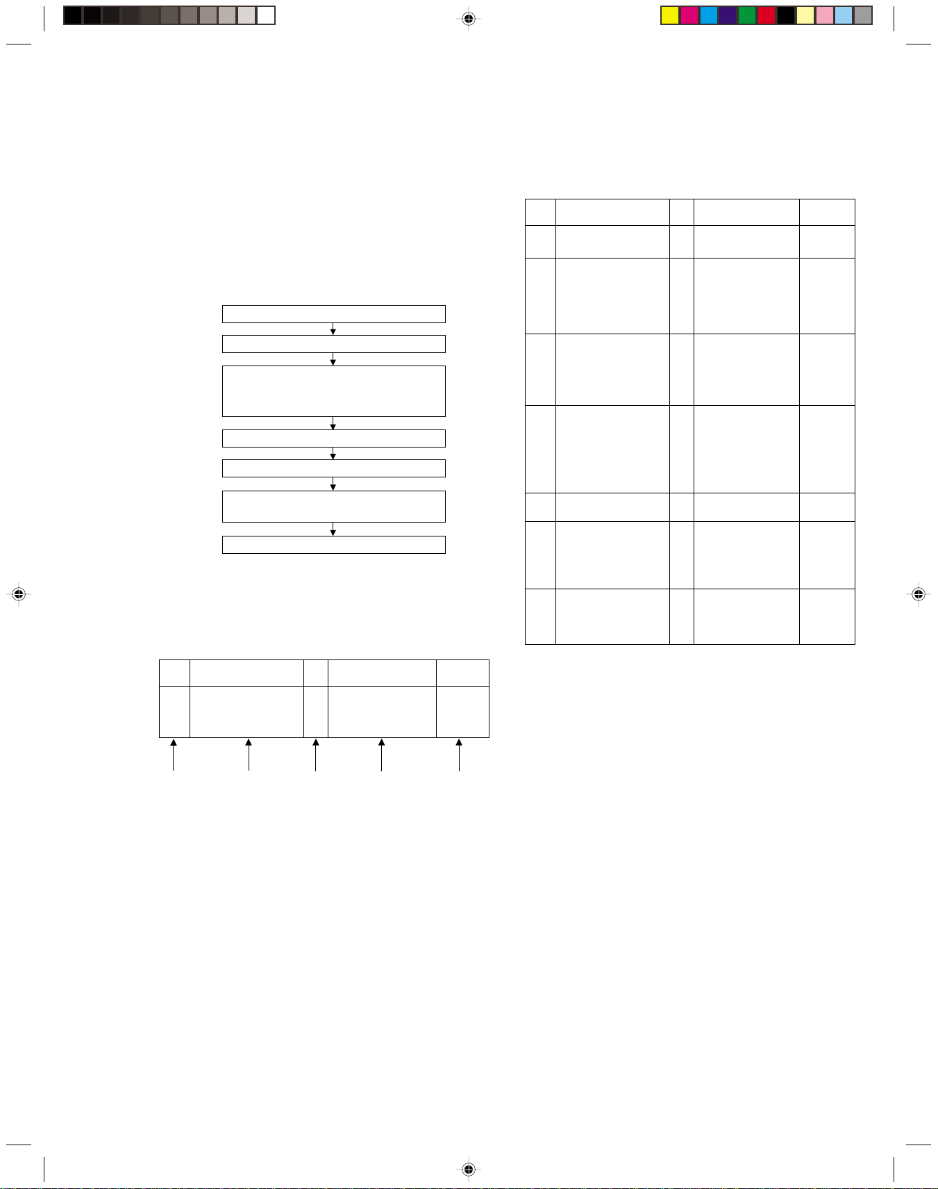
Table 1-8-3a
When the mechanism mode cannot be changed to an-
other mode even when the loading motor has rotated
for more than 4 seconds in the loading direction, [E:01]
is identified and the power is turned off.
When the mechanism mode cannot be changed to an-
other mode even when the loading motor has rotated
for more than 4 seconds in the unloading direction, [E:02]
is identified and the power is turned off.
When the take-up reel pulse has not been generated for
more than 4 seconds in the capstan rotating mode, [E:03]
is identified, the pinch rollers are turned off and stopped,
and the power is turned off. However, the reel EMG is
not detected in STILL/SLOW modes.
When the drum FG pulse has not been input for more
than 3 seconds in the drum rotating mode, [E:04] is iden-
tified, the pinch rollers are turned off and stopped, and
the power is turned off.
When the eject operation does not complete in 3 sec-
onds after the start, [E:05] is identified, the pinch rollers
are turned off and stopped, and the power is turned off.
When the cassette insertion operation does not complete
in 3 seconds after the start, the cassette is ejected. In
addition, when the operation does not complete within
3 seconds after the start, [E:05] is also identified and the
power is turned off immediately.
When the capstan FG pulse has not been generated for
more than 1 second in the capstan rotating mode, [E:06]
is identified, the pinch rollers are turned off and stopped,
and the power is turned off.However, the capstan EMG
is not detected in STILL/SLOW/FF/REW modes.
When short-circuiting of the SW power supply with GND
has lasted for 0.5 second or more, [E:07] is identified,
all the motors are stopped and the power is turned off.
When DD tilting does not complete in 4 seconds, [E:08]
is identified, the tilt motor is stopped and the power is
turned off.
When the DD FG pulse is not generated within 2.5 sec-
onds, [E:09] is identified, the tilt motor is stopped and
the power is turned off.
When the supply reel pulse has not been generated for
more than 10 seconds in the capstan rotating mode,
[E:0A] is identified and the cassette is ejected (but the
power is not turned off). However, note that the reel EMG
is not detected in the SLOW/STILL mode.
1.
The mechanism is locked in the middle of mode transition.
2
. The mechanism is locked at the loading end due to the encoder position
reading error during mode transition.
3.
Power is not supplied to the loading MDA.
1.
The mechanism is locked in the middle of mode transition.
2.
The mechanism is locked at the unloading end due to the encoder posi-
tion reading error during mode transition.
3.
Power is not supplied to the loading MDA.
1.
The take-up reel pulse is not generated in the FWD transport modes (PLAY/
FWD SEARCH/FF, etc.) because;
1) The idler gear is not meshed with the take-up reel gear;
2)
The idler gear is meshed with the take-up reel gear, but incapable of wind-
ing due to too large mechanical load (abnormal tension);
3) The take-up reel sensor does not output the FG pulse.
2.
The supply reel pulse is not generated in the REV transport modes (REV
SEARCH/REW, etc.) because;
1) The idler gear is not meshed with the supply reel gear.
2) The idler gear is meshed with the supply reel gear, but incapable of wind-
ing due to too large a mechanical load (abnormal tension);
3) The supply reel sensor does not output the FG pulse.
3.
Power is not supplied to the reel sensors.
1.
The drum could not start or the drum rotation has stopped due to too large
a load on the tape, because;
1) The tape tension is abnormally high;
2)
The tape is damaged or a foreign object (grease, etc.) adheres to the tape.
2.
The drum FG pulse did not reach the System controller CPU because;
1) The signal circuit is disconnected in the middle;
2) The FG pulse generator (hall device) of the drum is faulty.
3.
The drum control voltage (DRUM CTL V) is not supplied to the MDA.
4.
Power is not supplied to the drum MDA.
1.
The cassette cannot be ejected due to a failure in the drive mechanism of
the housing.
2.
When the housing load increases during ejection, the loading motor is
stopped because of lack of headroom in its drive torque.
Housing load increasing factors: Temperature environment (low tempera-
ture, etc.), mechanism wear or failure.
3.
The sensor/switch for detecting the end of ejection are not functioning normally.
4.
The loading motor drive voltage is lower than specified or power is not sup-
plied to the motor (MDA).
5.
When the user attempted to eject a cassette, a foreign object (or perhaps
the user's hand) was caught in the opening of the housing.
1.
The capstan could not start or the capstan rotation has stopped due to too
large a load on the tape, because;
1) The tape tension is abnormally high (mechanical lock);
2) The tape is damaged or a foreign object (grease, etc.) is adhered to the
tape (occurrence of tape entangling, etc.).
2.
The capstan FG pulse did not reach the System controller CPU because;
1) The signal circuit is disconnected in the middle;
2) The FG pulse generator (MR device) of the capstans is faulty.
3.
The capstan control voltage (CAPSTAN CTL V) is not supplied to the MDA.
4.
Power is not supplied to the capstan MDA.
1.
The SW 5 V power supply circuit is shorted with GND.
2.
The SW 12 V power supply circuit is shorted with GND.
1. The absolute value sensor is defective. (The soldered parts have separated.)
2. The pull-up resistor at the absolute sensor output is defective. (The soldered parts
have separated.)
3. Contact failure or soldering failure of the pins of the connector (board-to-board) to the
absolute value sensor.
4.
The absolute value sensor data is not sent to the System Controller CPU.
1. The FG sensor is defective. (The soldered parts have separated.)
2. The pull-up resistor at the FG sensor output is defective. (The soldered parts have
separated.)
3. Contact failure or soldering failure of the pins of the connector (board-to-board) to the FG sensor.
4. The power to the sensor is not supplied. (Connection failure/soldering failure)
5. The FG pulse is not sent to the System Controller CPU.
6.
The tilt motor is defective. (The soldered parts have separated.)
7. The drive power to the tilt motor is not supplied. (Connection failure/soldering failure)
8. The tilt motor drive MDA - IC is defective.
9. Auto-recovery of the DD tilting cannot take place due to overrun.
1.
The supply reel pulse is not generated in the FWD transport mode (PLAY/
FWD SEARCH/FF, etc.) because;
1) PLAY/FWD or SEARCH/FF is started while the tape in the inserted cas-
sette is cut in the middle;
2) A mechanical factor caused tape slack inside and outside the supply
reel side of the cassette shell. In this case, the supply reel will not rotate
until the tape slack is removed by the FWD transport, so the pulse is not
generated until then;
3) The FG pulse output from the supply reel sensor is absent.
2.
The take-up reel pulse is not generated in the REV transport mode (REV
SEARCH/REW, etc.).
1) REV SEARCH/REW is started when the tape in the inserted cassette
has been cut in the middle;
2) A mechanical factor caused tape slack inside and outside the take-up
reel side of the cassette shell. In this case, the supply reel will not rotate
until the tape slack is removed by the REV transport, so the pulse will
not be generated until that time;
3) The FG pulse output from the take-up reel sensor is absent.
3.
The power to a reel sensor is not supplied.
FDP CONTENT CAUSE
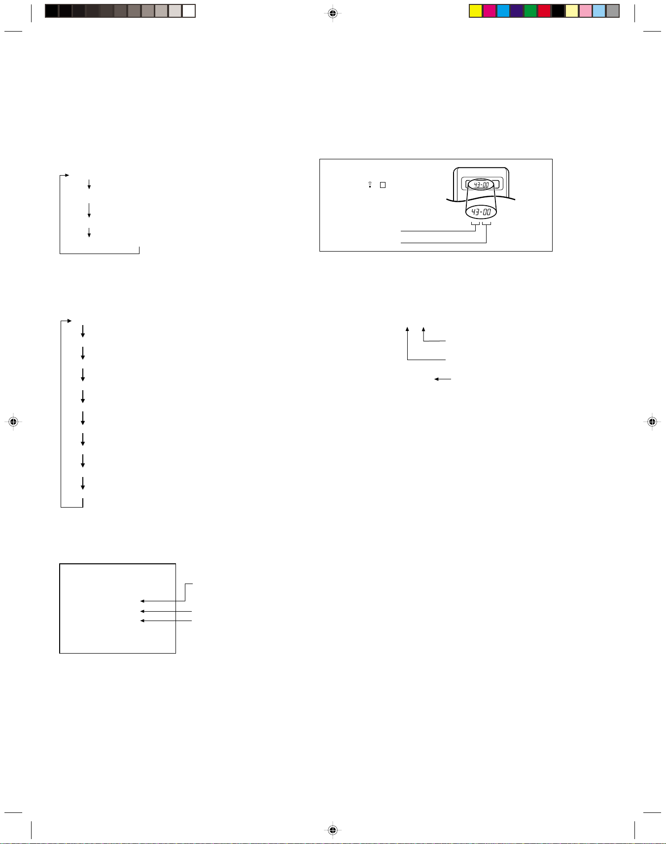
Presupposing the presence of the control pulse output in the PLAY mode, when the value obtained by mixing the two V.FM output
channels (without regard to the A.FM output) has remained below a certain threshold level for more than 10 seconds, [E:C1] or [E:U1]
is identified and recorded in the emergency history. During the period in which a head clog is detected, the FDP and OSD repeat the
“3-second warning display”and “7-second noise picture display”alternately.
EMG code : “E:C1”or “E:U1”/ FDP : “U:01”/ OSD : “Try cleaning tape.”or “Use cleaning cassette.”
The head clog warning is reset when the above-mentioned threshold has been exceeded for more than 2 seconds or the mode is
changed to another mode than PLAY.
EC1 or EU1:
Head clog warning
E0A:Supply Reel
Pulse EMG
E07: SW Power
Short-Circuit
EMG
E06: Capstan FG
EMG
E05: Cassette Eject
EMG
E04: Drum FG
EMG
E03: Take Up Reel
Pulse EMG
E02:
Unloading EMG
E01: Loading EMG
E08:
DD Initialized
(Absolute
Position
Sensor)
EMG
E09: DD FG EMG
www.freeservicemanuals.info
3/3/2019
Digitized in Heiloo the Netherlands
Not for sale!

1-8
1.8.4 EMG detail information <1>
The status (electrical operation mode) of the VCR and the sta-
tus (mechanism operation mode/sensor information) of the
mechanism in the latest EMG can be confirmed based on the
figure in EMG detail information <1> .
[FDP/OSD display]
* 1 : * 2 : 34
* 1 : Deck operation mode at the moment of EMG
* 2 : Mechanism operation mode at the moment of EMG
3–: Mechanism sensor information at the moment of EMG
–4 : Mechanism mod
e position at the moment of EMG
Note:
•
For EMG detailed information <1>, the content of the code
that is shown on the FDP (or OSD) differs depending on
the parts number of the system control microprocessor
(IC3001) of the VCR. The system control microprocessor
parts number starts with two letters, refer these to the cor-
responding table.
* 1 : Deck operation mode
[Common table of MN*, HD* and M3*]
00 - Mechanism being initialized
01 00 STOP with pinch roller pressure off (or tape present with P.OFF)
02 01 STOP with pinch roller pressure on
03 - POWER OFF as a result of EMG
04 04 PLAY
0C 0E REC
10 11 Cassette ejected
20 22 FF
21 - Tape fully loaded, START sensor ON, short FF
22 - Cassette identification FWD SEARCH before transition to FF (SP
x7-speed)
24 26 FWD SEARCH (variable speed) including x2-speed
2C 2E INSERT REC
40 43 REW
42 - Cassette identification REV SEARCH before transition to REW (SP
x7-speed)
44 47 REV SEARCH (variable speed)
4C 4C AUDIO DUB
6C 6E INSERT REC (VIDEO + AUDIO)
84 84 FWD STILL / SLOW
85 85 REV STILL / SLOW
8C 8F REC PAUSE
8D - Back spacing
8E - Forward spacing (FWD transport mode with BEST function)
AC AF INSERT REC PAUSE
AD - INSERT REC back spacing
CC CD AUDIO DUB PAUSE
CD - AUDIO DUB back spacing
EC EF INSERT REC (VIDEO + AUDIO) PAUSE
ED - INSERT REC (VIDEO + AUDIO) back spacing
* 2 : Mechanism operation mode
[Common table of MN* and M3*]
[Table of HD*]
Display
Mechanism operation mode
00 STOP with pinch roller pressure off
01 STOP with pinch roller pressure on
02 U/L STOP (or tape being loaded)
04 PLAY
05 PLAY (x1-speed playback using JOG)
0E REC
11 Cassette ejected
22 FF
26 FWD SEARCH (variable speed) including x2-speed
2E INSERT REC
43 REW
47 REV SEARCH
4C AUDIO DUB
6E INSERT REC (VIDEO + AUDIO)
84 FWD STILL/SLOW
85 REV STILL/SLOW
8F REC PAUSE
AF INSERT REC PAUSE
C7 REV SEARCH (x1-speed reverse playback using JOG)
CD AUDIO DUB PAUSE
EF INSERT REC (VIDEO + AUDIO) PAUSE
F0 Mechanism being initialized
F1 POWER OFF as a result of EMG
F2 Cassette being inserted
F3 Cassette being ejected
F4 Transition from STOP with pinch roller pressure on to STOP with pinch
roller pressure off
F5 Transition from STOP with pinch roller pressure on to PLAY
F6 Transition from STOP with pinch roller pressure on to REC
F7 Cassette type detection SEARCH before FF/REW is being executed
F8 Tape being unloaded
F9 Transition from STOP with pinch roller pressure off to STOP with pinch
roller pressure on
FA Transition from STOP with pinch roller pressure off to FF/REW
FB Transition from STOP with pinch roller pressure off to REC.P (T.REC,etc.)
FC Transition from STOP with pinch roller pressure off to cassette type de-
tection SEARCH
FD Short REV being executed after END sensor on during unloading
FE Tension loosening being executed after tape loading (STOP with pinch
roller pressure on)
Display Deck operation mode
MN*/M3* HD*
00 00 Command standby (Status without executing command)
02 02 POWER OFF by EMG occurrence
04 04 Moving to the adjacent position in the LOAD direction
06 06 Moving to the adjacent position in the UNLOAD direction
08 08 Cassette ejection being executed / Cassette housing ejection being
executed
- 0A Mode transition to STOP with cassette ejection end
0A 0C Cassette insertion being executed
0C 0E Tape being loaded
0E 10 Tape being unloaded
10 12 Mode transition to STOP with pinch roller compression ON
12 14 Mode transition to STOP with pinch roller compression OFF
14 16
Mode transition to STOP with pinch roller compression OFF as a result
of POWER OFF
16 18
Mode transition to STOP with pinch roller compression ON as a result
of POWER ON
18 1A Mode transition to PLAY
1A 1C Mode transition to FWD SEARCH
1C 1E Mode transition to REC
1E 20 Mode transition to FWD STILL / SLOW
20 22 Mode transition to REV STILL / SLOW
22 24 Mode transition to REV SEARCH
24 26 Mode transition from FF / REW to STOP
26 28 Mode transition to FF
28 2A Mode transition to REW
2A 2C 4 sec. of REV as a result of END sensor going ON during loading
2C 2E
Short FF / REV as a result of END sensor going ON during unloading
2E 30 Mechanism position being corrected due to overrun
80 80 Mechanism in initial position (Dummy command)
Display Mechanism operation mode
MN* M3*
www.freeservicemanuals.info
3/3/2019
Digitized in Heiloo the Netherlands
Not for sale!

1-9
-0 -7 - Initial value
-1 -0 - EJECT position
- - -0 EJECT position (Cassette housing drive mode)
-2 -7 - Housing operating
- - -1 Between EJECT and U / L STOP
-3 -1 -2 U / L STOP position
- - -3 Guide arm drive position
-4 -7 -4 Tape being loaded / unloaded (When the pole base is
located on the front side of the position just beside the
drum)
-5 -2 -5 Tape being loaded / unloaded (When the pole base is
located on the rear side of the position just beside the
drum)
-6 -7 -6 Pole base compressed position
-7 -3 -F FF / REW position
-8 -7 -F Between FF / REW and STOP with pinch roller compres-
sion ON
-9 -4 -F STOP with pinch roller compression OFF
-A -7 -E Between STOP with pinch roller compression OFF and
REV
-B -5 - REV (REV STILL / SLOW) position
- - -D REV position
- - -C Between REV and REV STILL / SLOW
- - -B REV STILL / SLOW position
-C -7 - Between REV and FWD
- - -A Between REV STILL / SLOW and FWD STILL / SLOW
-D -6 - FWD (FWD STILL / SLOW) position
- - -9 FWD STILL / SLOW position
-E -7 - Between FWD and PLAY
- - -8 Between FWD STILL / SLOW and PLAY
-F -6 -7 PLAY position
0- VHS Cassette insertion Tab broken ON ON
1- VHS Cassette insertion Tab broken ON OFF
2- VHS Cassette insertion Tab broken OFF ON
3- VHS Cassette insertion Tab broken OFF OFF
4- VHS Cassette insertion Tab present ON ON
5- VHS Cassette insertion Tab present ON OFF
6- VHS Cassette insertion Tab present OFF ON
7- VHS Cassette insertion Tab present OFF OFF
8- S-VHS Cassette ejection Tab broken ON ON
9- S-VHS Cassette ejection Tab broken ON OFF
A- S-VHS Cassette ejection Tab broken OFF ON
B- S-VHS Cassette ejection Tab broken OFF OFF
C- S-VHS Cassette ejection Tab present ON ON
D- S-VHS Cassette ejection Tab present ON OFF
E- S-VHS Cassette ejection Tab present OFF ON
F- S-VHS Cassette ejection Tab present OFF OFF
3–: Mechanism sensor information
[Common table of MN*, HD* and M3*]
Mechanism sensor information
Display
MN* / HD* M3* REC safety Start End
S-VHS SW CASS SW SW sensor sensor
* 6 : Cassette tape winding position
The cassette tape winding position at the moment of EMG is
displayed by dividing the entire tape (from the beginning to the
end) in 22 sections using a hex number from “00”to “15”.
“00”: End of winding
“15”: Beginning of winding
“FF or ––” : Tape position not identified
–4 : Mechanism mode position
[Common table of MN*, HD* and M3*]
Display Mechanism mode position
MN* HD* M3*
Note:
•
The values of cassette tape type <2> in the above table
are typical values with representative cassette tapes.
* 7 : Cassette tape type <2> (Winding area)
Display Cassette tape type <2>
00 Cassette type not identified
07 Small reel, thick tape T-5
08 - 0E C cassette, thick tape TC-10
09 - 15 C cassette, thick tape TC-20P
0A - 0B Small reel, thick tape T-20
0A - 16 C cassette, thin tape TC-30
0A - 16 C cassette, thin tape TC-40
0D - 0F Small reel, thick tape T-40
11 - 14 Small reel, thick tape T-60
15 - 18 Small reel, thick tape T-80 / DF-160
17 - 1A Small reel, thick tape T-90 / DF-180
19 - 1D Small reel, thick tape T-100
1D - 21 Small reel, thick tape T-120 / DF-240
1E - 1F Small reel, thin tape T-140
1F - 23 Small reel, thick tape T-130
21 - 23 Small reel, thin tape T-160
21 - 23 Small reel, thin tape T-168
22 - 24 Small reel, thick tape DF-300
22 - 24 Small reel, thin tape T-180 / DF-360
22 - 24 Small reel, thin tape T-210 / DF-420
22 - 23 Large reel T-5
23 - 24 Large reel T-10
25 - 26 Large reel T-20
27 - 29 Large reel T-30
29 - 2B Large reel T-40
2D - 2F Large reel T-60
Notes:
•
Cassette tape type
<1>
is identified a few times during mode
transition and the identification count is variable depending on
the cassette tape type. If an EMG occurs in the middle of identi-
fication, the cassette tape type may not be able to be identified.
•
If other value than those listed in the above table is displayed,
the cassette tape type is not identified.
Display Cassette tape type <1>
00 Cassette type not identified
16
Large reel/small reel (T-0 to T-15/T-130 to T-210) not classified
82 Small reel, thick tape (T-120) identified/thin tape (T-140) identified
84 Large reel (T-0 to T-60) identified
92
Small reel, thick tape (T-130) identified/thin tape (T-160 to T-210) identified
93
Small reel, thick tape/C cassette (T-0 to T-100/C cassette) not classified
C3
Small reel, thick tape/C cassette (T-0 to T-100/C cassette) being classified
D3
Small reel, thick tape/C cassette (T-0 to T-100/C cassette) being classified
E1 C cassette, thick tape (TC-10 to TC-20) identified
E2 Small reel, thick tape (T-0 to T-100) identified
E9 C cassette, thin tape (TC-30 to TC-40) identified
F1
C cassette, thick tape/thin tape (TC-10 to TC-40) not classified
* 5 : Cassette tape type <1>
Note:
•EMG detail information <2> is the reference information
stored using the remaining tape detection function of the
cassette tape. As a result, it may not identify cassette cor-
rectly when a special cassette tape is used or when the
tape has variable thickness.
1.8.5 EMG detail information <2>
The type of the cassette tape and the cassette tape winding po-
sition can be confirmed based on the figure in EMG detail infor-
mation <2> .
[FDP/OSD display]
*5 : *6 : *7
* 5 : Type of the cassette tape in use <1>
* 6 : Winding position of the cassette tape in use
* 7 : Type of th
e cassette tape in use
<2>
(Winding area)
Note:
•In the case of the "HD*”microprocessor, as the display is
always "-7”at any intermediate position between modes,
the position of transitory EMG may sometimes not be lo-
cated.
www.freeservicemanuals.info
3/3/2019
Digitized in Heiloo the Netherlands
Not for sale!

2-1
SECTION 2
MECHANISM ADJUSTMENT
2.1 Before starting repair and adjustment
2.1.1 Precautions
(1) Unplug the power cord plug of the VCR before using your
soldering iron.
(2) Take care not to cause any damage to the conductor
wires when plugging and unplugging the connectors.
(3) Do not randomly handle the parts without identifying
where the trouble is.
(4) Exercise enough care not to damage the lugs, etc. dur-
ing the repair work.
(5) When reattaching the front panel assembly, make sure
that the door opener of the cassette holder assembly is
lowered in position prior to the reinstallation. (See SEC-
TION 1 DISASSEMBLY.)
(6) When using the Jig RCU, it is required to set the VCR to
the Jig RCU mode (the mode in which codes from the
Jig RCU can be received). (See SECTION 1 DISASSEM-
BLY.)
2.1.2 Checking for proper mechanical operations
Enter the mechanism service mode when you want to oper-
ate the mechanism when no cassette is loaded. (See SEC-
TION 1 DISASSEMBLY.)
2.1.3 Manually removing the cassette tape
1. In case of electrical failures
If you cannot remove the cassette tape which is loaded be-
cause of any electrical failure, manually remove it by taking
the following steps.
(1) Unplug the power cord plug from the power outlet.
(2) Refer to the disassembly procedure and perform the dis-
assembly of the major parts before removing the drum
assembly.
(3) Unload the pole base assembly by manually turning the
loading motor of the mechanism assembly toward the
front. In doing so, hold the tape by the hand to keep the
slack away from any grease. (See Fig.2-1-3a.)
(4) Bring the pole base assembly to a pause when it reaches
the position where it is hidden behind the cassette tape.
(5) Move the top guide toward the drum while holding down
the lug (A) of the bracket retaining the top guide. Like-
wise hold part (B) down and remove the top guide.
Section (C) of the top guide is then brought under the
cassette lid. Then remove the top guide by pressing the
whole cassette tape down. (See Fig.2-1-3b.)
(6) Remove the cassette tape by holding both the slackened
tape and the cassette lid.
(7) Take up the slack of the tape into the cassette. This com-
pletes removal of the cassette tape.
Note:
• For the disassembly procedure of the major parts and
details of the precautions to be taken, see “SECTION
1 DISASSEMBLY”.
Fig. 2-1-3b
Fig. 2-1-3a
Loading motor
Pole base assembly
Press
(C)
(A)
(B)
www.freeservicemanuals.info
3/3/2019
Digitized in Heiloo the Netherlands
Not for sale!

2-2
2. In case of mechanical failure
If you cannot remove the cassette tape which is loaded be-
cause of any mechanical failure, manually remove it by tak-
ing the following steps.
(1) Unplug the power cable and remove the top cover, front
panel assembly and others so that the mechanism as-
sembly is visible. (See SECTION 1 DASASSEMBLY.)
(2) While keeping the tension arm assembly of the mecha-
nism assembly free from tension, pull the tape on the pole
base assembly (supply or take-up side) out of the guide
roller. (See Fig.2-1-3c.)
(3) Take the spring of the pinch roller arm assembly off the
hook of the press lever assembly, and detach it from the
tape. (See Fig.2-1-3d.)
(4) In the same way as in the electrical failure instructions in
2.1.3-1(5), remove the top guide.
(5) Raise the cassette tape cover. By keeping it in that posi-
tion, draw out the cassette tape case from the cassette
holder and take out the tape.
(6) By hanging the pinch roller arm assembly spring back
on the hook, take up the slack of the tape into the cas-
sette.
Fig. 2-1-3d
Fig. 2-1-3c
Pole base assembly (take-up side)
Pole base assembly
(supply side)
Tension arm assembly
Guide pole guard
Pinch roller arm assembly
Press lever assembly
Take the spring
off the hook, and
detach it from the
tape.
2.1.4 Jigs and tools required for adjustment
Roller driver A/C head positioning tool
Back tension cassette gauge
Jig RCU
Torque gauge
Alignment tape
(SP, stairstep, PAL)
Alignment tape
(LP, stairstep, PAL)
www.freeservicemanuals.info
3/3/2019
Digitized in Heiloo the Netherlands
Not for sale!

2-3
2.1.5 Maintenance and inspection
1. Location of major mechanical parts
In this chapter, the two mechanism speeds are described by comparing the speeds of the standard type and the high-speed
FF/REW type.
It is possible to distinguish between these two types of mechanism by the diameters of their capstan pulleys.
The capstan pulley diameter for the standard type is approx. 32 mm.
The capstan pulley diameter for the high-speed FF/REW type is approx. 43 mm.
For information on the different parts used in the two mechanism types, please refer to the “Replacement of major parts”.
Fig. 2-1-5a Mechanism assembly top side
Stator assembly
UV catcher2 (supply and take-up side)
Drum assembly Head base
A/C head
Loading motor
Pinch roller arm
assembly
Guide pole guard
Press lever
assembly
Lid guide
Guide arm
assembly
Reel disk
(take-up side)
Sub brake assembly
(take-up side)
Main brake assembly
(take-up side)
Idler arm assembly
Idler lever
Main brake assembly
(supply side)
Reel disk
(supply side)
Rec safety lever
Tension brake
assembly
Adjust pin
Tension arm
assembly
Pole base assembly
(supply side)
Full erase head
Pole base assembly (take-up side)
T1
T26
T25
T24
T23
T22
T2
T3 T5 T7
T8
T9
T10
T11
T12
T13
T14
T15
T16T18
T20
T17T19T21
T6
Fig. 2-1-5b Mechanism assembly bottom side
Belt
(loading motor)
Capstan motor
Belt (capstan)
Capstan brake assembly
Loading arm gear (take-up side)
Loading arm gear (supply side)
Plate
(supply side)
Control plate
Worm gear
Control cam
Cassette gear
Rotary encoder
Change lever assembly Clutch unit
Take-up lever
Take-up head
Control
bracket1
Tension arm
bearing
B1
B22
B3 B5
B6
B7
B8
B9
B10
B12
B15
Rotary encoder guide
B16
B17
B18
Brake lever
B19
B20
B21
B14
B11
B4
B2
Direct gear
B13
Link lever
www.freeservicemanuals.info
3/3/2019
Digitized in Heiloo the Netherlands
Not for sale!

2-4
Guide rail Roller cam assembly
L2L1
Opener guide
Door
opener
Drive gear
Cassette housing bracket
Limit gear
Worm gear
Belt (loading motor)
Loading motor
R2
R3 R5
R4
R1
Fig. 2-1-5c Mechanism assembly left side
Fig. 2-1-5d Mechanism assembly right side
5. Disassembling procedure table
The following table indicates the order in which parts are re-
moved for replacement. To replace parts, remove them in
the order of 1 to 18 as shown in the table. To install them,
reverse the removal sequence.
The symbols and numbers preceding the individual part
names represent the numbers in the “Location of major me-
chanical parts”table. Also, the “T”, “B”, and “T/B”on the right
of each part name shows that the particular part is removed
from the front, from the back, and from both sides of the
mechanism, respectively.
2. Cleaning
Regular cleaning of the transport system parts is desirable
but practically impossible. So make it a rule to carry out clean-
ing of the tape transport system whenever the machine is
serviced.
When the video head, tape guide and/or brush get soiled,
the playback picture may appear inferior or at worst disap-
pear, resulting in possible tape damage.
(1) When cleaning the upper drum (especially the video
head), soak a piece of closely woven cloth or Kimu-wipe
with alcohol and while holding the cloth onto the upper
drum by the fingers, turn the upper drum
counterclockwise.
Note:
•Absolutely avoid sweeping the upper drum vertically
as this will cause damage to the video head.
(2) To clean the parts of the tape transport system other than
the upper drum, use a piece of closely woven cloth or a
cotton swab soaked with alcohol.
(3) After cleaning, make sure that the cleaned parts are com-
pletely dry before using the video tape.
3. Lubrication
With no need for periodical lubrication, you have only to lu-
bricate new parts after replacement. If any oil or grease on
contact parts is soiled, wipe it off and newly lubricate the
parts.
Note:
•See the “mechanism assembly”diagram of the parts
list for the lubricating or greasing spots, and for the
types of oil or grease to be used.
~1000H ~2000H
Upper drum assembly ¤R R
A/C head ¤R ¤R
Lower drum assembly
¤¤R
Pinch roller arm assembly ¤¤
Full erase head ¤¤
Tension arm assembly ¤¤
Capstan motor (Shaft) ¤¤
Guide arm assembly ¤¤
Capstan motor R
Capstan brake assembly R
Main brake assembly R
Belt (Capstan) RR
Belt (Loading motor) R
Loading motor R
Clutch unit R
Worm gear R
Control plate R
Brush ¤R ¤R
Tension brake assembly RR
Rotary encoder R
4. Suggested servicing schedule for main components
The following table indicates the suggested period for such
service measures as cleaning,lubrication and replacement.
In practice, the indicated periods will vary widely according
to environmental and usage conditions.However, the indi-
cated components should be inspected when a set is brought
for service and the maintenance work performed if neces-
sary. Also note that rubber parts may deform in time,even if
the set is not used.
Operation Hours
System Parts Name
¤: Cleaning
R: Inspection or replacement if necessary
Table 2-1-5a
Other Drive Tape transport
www.freeservicemanuals.info
3/3/2019
Digitized in Heiloo the Netherlands
Not for sale!

2-5
Symbols and numbers
Symbols and numbers
Number of removal steps
Guide rail
Roller cam assembly
Cassette housing bracket
Opener guide
Relay gear
Cassette holder assembly
Drive gear
Drive arm
Pinch roller arm assembly
Guide arm assembly
Press lever assembly
UV catcher2
Rotary encoder
Clutch unit
Change lever assembly
Direct gear
Coupling gear
Link lever
Worm gear
Control bracket1
Control plate
Loading arm gear (supply side)
Loading arm gear (take-up side)
Take-up lever
Sub brake assembly (take-up side)
Main brake assembly (take-up side)
Reel disk (take-up side)
Tension brake assembly
Tension arm assembly
Idler lever
Brake lever
(
*1
)
Front (T)/Back (B) of mechanism
(Reference items)
Replacement parts
Removal parts
L1
L1
L2
L2
R4
R1
R2
R5
R3
T9
T12
T11
T6
T7
B1
T1
T17
T10
T14
T15
T19
T13
T22
T20
T24
B9
T18
T16
B19
B16
B7
B8
B5
B4
B3
B11
B10
T25
B15
B12
B14
B13
B17
B18
B20
B21
R4 R1 R3 T9 T12 T11 B15 B12 B14 B13 B17 B21 B7 B8 B5 B4 B11 T14 T15 T13 T22 T24 T18 B19
T1
2.2.3 Guide rail T 1
2.2.3 Roller cam assembly T 1
2.2.3 Cassette housing bracket T 1
2.2.3 Opener guide T 2
2.2.3 Door opener T 3
2.2.3 Relay gear T 3
2.2.3 Limit gear T 3
2.2.3 Cassette holder assembly T 6
2.2.3 Drive gear T 4
2.2.3 Drive arm T 8
2.2.4 Pinch roller arm assembly T 1
2.2.5 Guide arm assembly T 1
2.2.5 Press lever assembly T 3
2.2.6 A/C head T 1
2.2.7 Loading motor T 1
2.2.8 Capstan motor T/B 1
2.2.9 UV catcher2 T 1
2.2.9
Pole base assembly (take-up side)
T/B 2
2.2.9
Pole base assembly (supply side)
T/B 2
2.2.10 Rotary encoder B 1
2.2.11 Clutch unit B 1
2.2.12 Change lever assembly B 3
2.2.12 Direct gear B 4
2.2.12 Coupling gear B 5
2.2.12 Clutch gear B 6
2.2.13 Link lever B 1
2.2.14 Cassette gear B 2
2.2.14 Control cam B 2
2.2.14 Worm gear B 1
- Lid guide T/B 5
2.2.15 Control bracket1 B 1
2.2.15 Control plate B 6
2.2.16 Loading arm gear (supply side) B 7
2.2.16
Loading arm gear (take-up side)
B8
2.2.16 Loading arm gear shaft B 9
2.2.17 Take-up lever T/B 7
2.2.17 Take-up head T/B 8
2.2.17 Control plate guide T/B 8
2.2.18 Capstan brake assembly T/B 7
2.2.19
Sub brake assembly(take-up side)
T/B 15
2.2.20
Main brake assembly(take-up side)
T/B 16
2.2.20
Main brake assembly(supply side)
T/B 9
2.2.20 Reel disk (take-up side) T/B 16
2.2.21 Tension brake assembly T/B 9
2.2.21 Reel disk (supply side) T/B 10
2.2.21 Tension arm assembly T/B 10
2.2.21 Tension arm bearing T/B 10
2.2.22 Idler lever T/B 17
2.2.22 Idler arm assembly T/B 18
- Brake lever (
*1
) T/B 18
- Rotary encoder guide T/B 19 1 2 3 4 5 6 7 8 9 10 11 12 13 14 15 16 17 18
1 2 3 4 5 6 7 8 9 10 11 12 13 14 15 16 17
1 2 3 4 5 6 7 8 9 10 11 12 13 14 15 16 17
1 2 3 4 5 6 7 8 9 10 11 12 13 14 15 16
1 2 3 4 5 6 7 8 9
1 2 3 4 5 6 7 8 9
1 2 3 4 5 6 7 8 9
1 2 3 4 5 6 7 8
1 2 3 4 5 6 7 8 9 10 11 12 13 14 15
1 2 3 4 5 6 7 8
1 2 3 4 5 6 7 8 9 10 11 12 13 14 15
1 2 3 4
12
12
3
12
1
1
1
2
3
4
1 2 3 4 5
5 6
1 2 3 4 5 6
1 2 3 4 5 6
7
12
12
12
1
1
2
3
12 3
4 5
1 2 3 4 5
6 7
7
1 2 3 4 5 6
1 2 3 4 5 6
1 2 3 4 5 6 7
1 2 3 4 5 6
1 2 3 4 5
1 2 3 4
1
1
1
2
3 4
5
6
7
8
7
8 9 10 11 12 13 14
Table 2-1-5b
Note:
•The parts with marked ( *
) have different types of mecha-
nisms (standard type or high-speed FF/REW type).
*1 : Uses the standard type mechanism only.
*2 : Uses the high-speed FF/REW type mechanism only.
www.freeservicemanuals.info
3/3/2019
Digitized in Heiloo the Netherlands
Not for sale!

2-6
(4) While swinging the lock levers (R) and (L) of the cassette
holder assembly toward the front, slide the cassette
holder assembly until its legs come to where the guide
rail and the roller cam assembly have been removed (so
that the drive arm is upright). (See Fig.2-2-3c.)
Fig. 2-2-3c
Cassette holder assembly
Lock lever (L) Drive arm
(Upright)
Le
g
Le
g
s
2.2.3 Cassette holder assembly
1. How to remove
(1) Remove the guide rail and roller cam assembly. (See
Fig.2-2-3a.)
(3 lugs on the guide rail and one lug on the roller cam
assembly)
Fig. 2-2-2a
Worm gear
Guide hole
Control cam
Chassis hole
Control plate
Mark E
Fig. 2-2-3b
(2) Remove the two slit washers and remove the cassette
housing bracket. (See Fig.2-2-3b.)
(3) Remove the opener guide, spring(A), door opener, relay
gear and limit gear. (See Fig.2-2-3b.)
Fig. 2-2-3a
Lugs Lug
Lug
Guide rail
Roller cam
assembly
Limit gear
Relay gear
Opener guide
Spring(A)
Cassette housing bracket
Slit washers
Door opener
2.2 Replacement of major parts
2.2.1 Before starting disassembling (Phase matching
between mechanical parts)
The mechanism of this unit is closely linked with the rotary
encoder and system controller circuits.
Since the system controller detects the status of mechani-
cal operation in response to phases of the rotary encoder
(internal switch positions), the mechanism may not operate
properly unless such parts as the rotary encoder, control
plate, loading arm gear, control cam, cassette gear, limit gear,
relay gear and drive gear are installed in their correct posi-
tions.
Especially, this model is not provided with any cassette hous-
ing assembly, so that cassette loading and unloading must
be accomplished by operation of the cassette holder assem-
bly. The latter is in turn driven by such parts as the drive
gear, relay gear and limit gear. Exercise enough care, there-
fore, to have the phases of all this gear matching one an-
other. (For information on phase matching of the mechanism,
see the instructions on how to install individual parts.)
This unit is provided with a mechanism assembly mode. It is
therefore necessary to enter this mode for assembling and
disassembling procedures.
This mode is usually not in use, manually set it when it is
required.
2.2.2 How to set the “Mechanism assembling mode”
Remove the mechanism assembly and place it bottom side
up. (See SECTION 1 DISASSEMBLY.) Turn the worm gear
toward the front so that the guide hole of the control cam is
brought into alignment with the hole at the mechanism as-
sembly chassis. This position renders the mechanism assem-
bling mode operational. Make sure that the control plate is
located in alignment with the mark E. (See Fig.2-2-2a.)
www.freeservicemanuals.info
3/3/2019
Digitized in Heiloo the Netherlands
Not for sale!

2-7
Fig. 2-2-3d
(5)
While holding the left side of the cassette holder, lift the
cassette holder assembly so that the three legs on the
left side are all released. Then pull the legs (A) and (B)
on the right side out of the rail and also pull up the leg(C).
(See Fig.2-2-3d and Fig.2-2-3e.)
(6) Draw out the drive gear, and remove the drive arm.
Fig. 2-2-3e
Cassette holder assembly
(A)
(C) (B)
Fig. 2-2-3f
Hole
Hole
Drive arm
Drive gear
Drive arm
(1)
(2)
(A)
(B)
Main deck right side
Fig. 2-2-3g
2. How to install (Phase matching)
(1) Insert the section (A) of the drive arm into the section (B)
of the main deck.
(2) Insert the section (1) of the drive gear into the round hole,
and the section (2) into the square hole on the drive arm.
(See Fig.2-2-3f.)
(3) Hold the drive arm upright and fit the leg (C) on the right
side of the cassette holder assembly into the groove. (See
Fig.2-2-3g.)
(4) While swinging the lock lever (R) of the cassette holder
assembly toward the front, put the legs (A) and (B) into
the rail. (See Fig.2-2-3g.)
(5) Drop the three legs on the left side of the cassette holder
assembly into the groove at one time. (See Fig.2-2-3h.)
(6) Slide the whole cassette holder assembly toward the front
to bring it to the eject end position.
(7) Install the limit gear so that the notch on the outer cir-
cumference of the limit gear is brought into alignment with
the guide hole on the main deck. (See Fig.2-2-3i.)
(8) Install so that the notch on the periphery of the relay gear
is aligned with the notch of the main deck and that hole
A of the relay gear is aligned with the hole A of the limit
gear and that hole B of the relay gear is aligned with the
hole B of the drive gear. (See Fig.2-2-3i.)
(9) Install the door opener, opener guide, spring(A) and cas-
sette housing bracket and fasten the two slit washers.
Cassette holder assembly
Drive arm
Lock lever (R)
(A)
(C) (B)
Fig. 2-2-3h
Cassette holder assembly
www.freeservicemanuals.info
3/3/2019
Digitized in Heiloo the Netherlands
Not for sale!

2-8
2.2.7 Loading motor
1. How to remove
(1) Remove the belt wound around the worm gear.
(2) Open the two lugs of the motor guide and remove the
loading motor, loading motor board assembly and motor
guide altogether by pulling them up.
(3) When replacing the loading motor board assembly, take
care with the orientation of the loading motor. (Install so
that the loading motor label faces upward.)
(4) When the motor pulley has been replaced, choose the
fitting dimension as indicated in Fig.2-2-7a.
2.2.4 Pinch roller arm assembly
1. How to remove
(1) Remove the spring from the hook of the press lever as-
sembly.
(2) Remove the slit washer and remove the pinch roller seat
2. (See Fig.2-2-4a.)
(3) Remove the pinch roller arm assembly by pulling it up.
Fig. 2-2-5a
2.2.6 A/C head
1. How to remove
(1) Remove the two screws (A) and remove the A/C head
together with the head base.
(2) When replacing only the A/C head, remove the three
screws (B) while controlling the compression spring.
Fig. 2-2-6a
Fig. 2-2-6c
Fig. 2-2-4a
2.2.5 Guide arm assembly and press lever assembly
1. How to remove
(1) Remove the spring and expand the lug of the lid guide in
the arrow-indicated direction. Then remove the guide arm
assembly by pulling it up.
(2) Remove the press lever assembly by pulling it up. (See
Fig.2-2-5a.)
Tension
spring
Press lever
assembly
Guide arm
assembly
LugLid guide
Head base
Screws(A)
A/C head
Compression
springs
Head base
A/C head board
assembly
A/C head
Screws(B)
Fig. 2-2-6b
2. How to install
(1) To make the post-installation adjustment easier, set the
temporary level as indicated in Fig.2-2-6c. Also make sure
that the screw center (centre) is brought into alignment
with the center (centre) position of the slot.
Head base
Head base
Screw
A/C head
A/C head
12.4 mm
Pinch roller seat2
Pinch roller arm
assembly
Pinch roller arm assembly
Slit washer
Spring
Press lever assembly
Fig. 2-2-3i
Relay gear
Drive gear Limit gear
Guide holeNotches Notch
B
AA
B
www.freeservicemanuals.info
3/3/2019
Digitized in Heiloo the Netherlands
Not for sale!

2-9
Fig. 2-2-8b
Loading motor board assembly
Loading motor
Motor guide
Worm gear
Belt
Lugs
6.5 ±0.2 mm
Motor pulley
LABEL
Fig. 2-2-7a
Fig. 2-2-8a
2.2.8 Capstan motor
1. How to remove
(1) Remove the belt (capstan) on the mechanism assembly
back side.
(2) Remove the three screws (A) and remove the capstan
motor.
Capstan motor
Belt
Screw(A)
Screws(A)
2. How to install (Centering the mounting position)
When the capstan motor has once been removed and then
reinstalled out of the initial correct position in the rotational
direction, the capstan motor current may be unstable during
operation in high or low temperatures. This may result in
greater Wow & Flutter and occasionally in power breakdown
because of current over - load. Install the capstan motor while
following the procedure given below.
(The capstan motor is centrally located when the unit is
shipped from the factory.)
(1) Provisionally tighten the three screws (A) securing the
capstan motor.
(2) Install the mechanism assembly to which the capstan
motor is provisionally fastened on the bottom chassis
which incorporates the Main board assembly. (No need
to tighten the screws for mounting the mechanism.)
Make sure that all the connectors for the mechanism as-
sembly and the Main board assembly are correctly in-
stalled as indicated in Fig. 2-2-8b.
(3) Making sure that the connector for the capstan motor is
correctly mounted, and securely tighten the three screws
(A).
Note:
•When the capstan motor has been replaced with a new
one, perform recording in the EP(or LP) mode for at
least 2 minutes at normal temperatures immediately be-
fore starting the FF/REW or SEARCH operations (Ag-
ing).
Spacer Spacer
Connector for
the capstan motor
2.2.9 Pole base assembly (supply or take-up side)
1. How to remove
(1) Remove the UV catcher 2 on the removal side by loos-
ening the screw (A).
(2) Remove the pole base assembly on the supply side from
the mechanism assembly by loosening the screw (B) on
the mechanism assembly back side and sliding the pole
base assembly toward the UV catcher 2.
(3) As for the pole base assembly on the take-up side, turn
the pulley of the loading motor to lower the cassette
holder because the screw (B) is hidden under the con-
trol plate. (See the “Procedures for Lowering the Cassette
holder assembly”of 1.3 DISASSEMBLY/ASSEMBLY
METHOD.) Further turn the motor pulley to move the cas-
sette holder until the screw (B) is no longer under the con-
trol plate (in the half-loading position). Then remove it as
done for the supply side by removing the screw (B).
Note:
•After reinstalling the Pole base assembly and the UV
catcher2, be sure to perform compatibility adjustment.
Fig. 2-2-9a
Screw(B)
Screw(A)
UV catcher2
Screw(A)
UV catcher2
www.freeservicemanuals.info
3/3/2019
Digitized in Heiloo the Netherlands
Not for sale!
Table of contents
Other Philips VCR System manuals

Philips
Philips VR332 User manual

Philips
Philips VR 525/02 User manual

Philips
Philips VR140/02 User manual

Philips
Philips VR200/07 User manual

Philips
Philips VR756/50 User manual

Philips
Philips VR625/77B User manual

Philips
Philips VR455/57 User manual

Philips
Philips VR757/01L User manual

Philips
Philips VR 757 User manual

Philips
Philips VR 337 User manual

Philips
Philips VRX344AT User manual

Philips
Philips VR810 User manual

Philips
Philips VR453/50 User manual

Philips
Philips VPA115AT User manual

Philips
Philips VRX463 User manual

Philips
Philips VR 260/07 User manual

Philips
Philips MatchLine VR 1200 User manual

Philips
Philips VR6390 User manual

Philips
Philips VRB413AT User manual

Philips
Philips VR 1070 User manual