PHOENIX CONTACT page 5 of 10
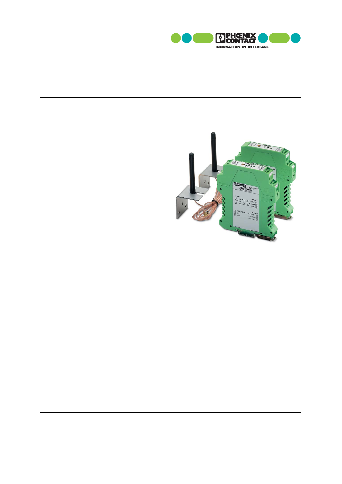
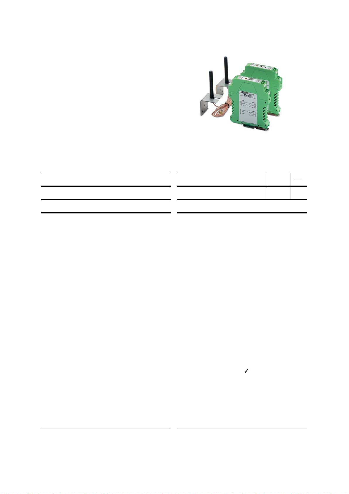
UnidirectionalWirelessTransmission System – RAD-ISM-2400-SET-UD-ANT
4. Use
Phoenix Contact hereby declares that the
RAD-ISM-2400-SET-UD-ANT radio system complies
with the basic requirements and other relevant
regulations specified in directive 1999/5/EC.
The radio system should only be operated using
authorizedaccessoriesfromPhoenix Contact.Theuse
of other additional components may invalidate the
device approval status.
4.1 Installation
The modules are snapped onto a DIN rail within a
control cabinet or control box.The control cabinet/box
must meet the requirements of EN 60 950-1:2001 in
terms of fire protection shielding.
In the electrical system of the building, a two-pole
disconnecting device must be provided to isolate the
equipment from the supply circuit.
In order to protect the modules against electrostatic
discharge when working on control cabinets, the
operating personnel must remove electrostatic
discharge before opening control boxes or control
cabinets and before touching the modules.
Observe the mounting instructions for the
antenna used.
The antenna cable is plugged into the
antenna connection sockets
77
77
/.
4.2Transmitter
Display and Diagnostic Elements
44
44
LED: Digital input 1 = Status of digital input 1
55
55
LED: Digital input 2 = Status of digital input 2
66
66
LED: RF link ON = Operating voltage U
B
present,
transmitter is sending data
Analog Input
22
22
The 4...20 mA analog input detects active and
passive current sensors.
For passive current sensors, the unregulated
operating voltage U
B
is provided at terminal block 7.
Digital Inputs
33
33
Both digital inputs on the transmitter can process
voltages from 5 - 30V AC/DC.They have a shared
groundpotential (terminalblock11) andareelectrically
isolated from the operating voltage U
B
.
The RAD-ISM-2400-SET-UD-ANT radio
system may only be used in the
countries listed below:
Austria, Belgium, Denmark, Finland,
France, Germany, Great Britain, Greece,
Iceland, Ireland, Italy, Luxembourg, the
Netherlands, Norway (not including
Spitzbergen), Portugal, Spain, Sweden,
and Switzerland.
4.3 Receiver
Display and Diagnostic Elements
RF link relay
TheRFlinkrelayin thereceiverdiagnoses thestatus
of the radio connection.It picks up when the radio
connection is established.
If no data packets are received correctly over a
period of approximately 3.4 seconds, the relay drops
again.
It picks up again automatically when the radio
connection is re-established.The RF link relay has a
Form C contact.
LED: Digital output 1 = Status of digital output 1
LED: Digital output 2 = Status of digital output 2
LED: RF link OFF = No operating voltage U
B
;
Flashes briefly approximately every 2 seconds
= No reception;
Flashes quickly = Connection breaking up
RSSI test socket
Avoltagemeasuringdevice(manualmultimeter)can
be connected to the RSSI test socket to measure a
voltage to GND, which provides information about
the received radio signal (the higher the voltage, the
better the reception).
Using the diagram below, the received signal
strength in dB can be determined using the voltage
value.This can be useful, e.g., when positioning and
aligning the antenna.
Analog Output (Also OperatingVoltage)
The analog output is supplied internally from the
unregulated operating voltage U
B
. Terminal block 4
provides a power source at which the actuator is wired
to ground (terminal block 5).
The output requires an internal drop voltage of 10V.
The maximum load at the current output with a
nominal voltage of 24V = (24 V - 10 V)/
20 mA = 700 Ohm.The maximum load therefore
depends on the operating voltage U
B
used.
Digital Outputs /
Two floating Form C contacts are used as the digital
outputs for the receiver.
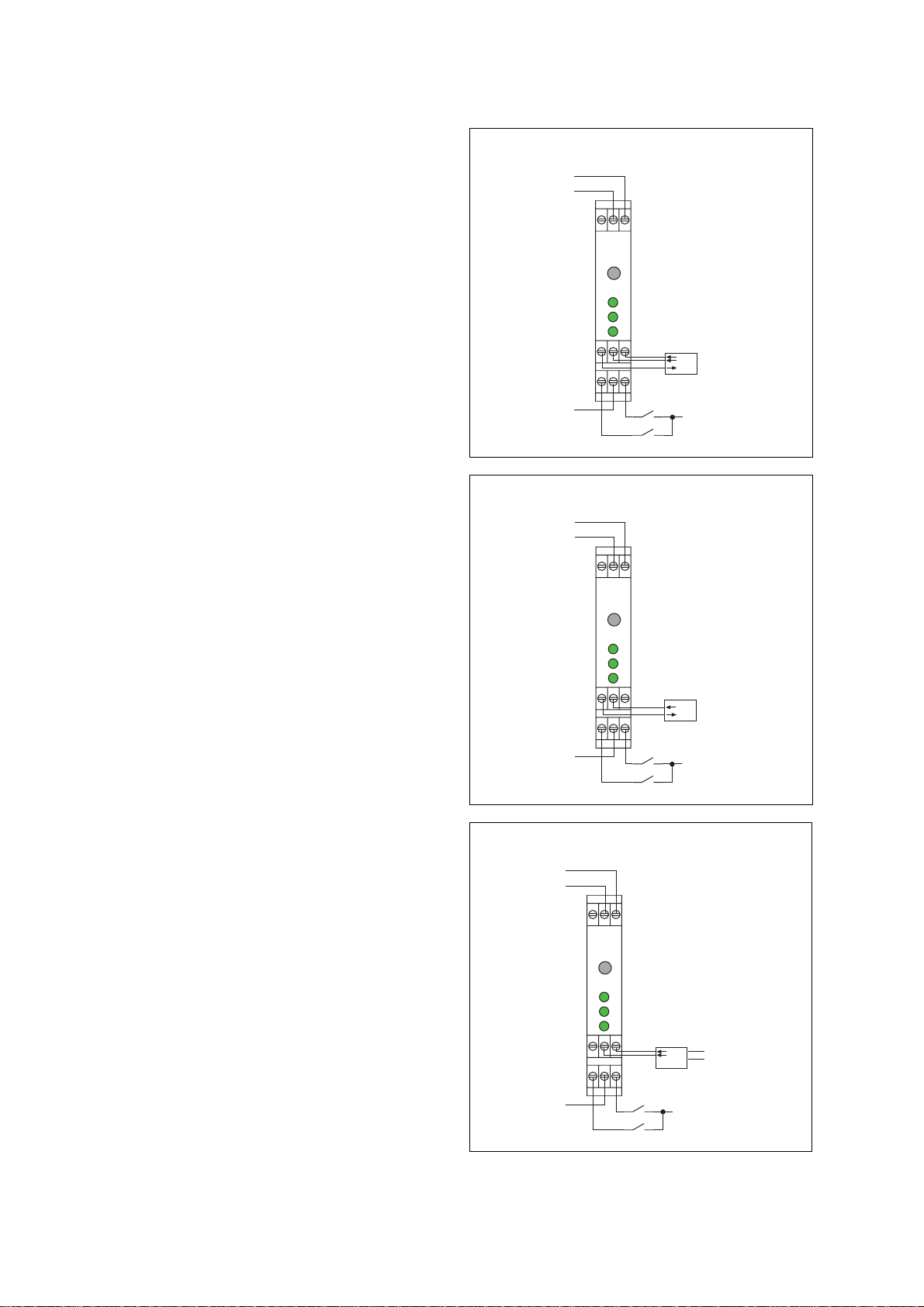
4.4 Behavior If the Radio Connection Is Interrupted
If the radio connection is interrupted, all outputs
(analog and digital) retain their last value or status (see
connection examples in Section 5).
To configure a reset response (revert back to "0") for
a digital signal or the analog signal when a radio
connection is interrupted, connect the RF link relay
contact in series.
To configure a reset response for all signals, use the
RF link relay to control one or more additional relays.
1,25
0
0,5
1
1,5
2
2,5
3
3,5
-125 -115 -105 -95 -85 -75 -65 -55 -45
signal loss (-dB)
RSSI [V]
1,75 2,25 2,75 3,25 3,75 4,25 4,75
0,75
4
4,5
5