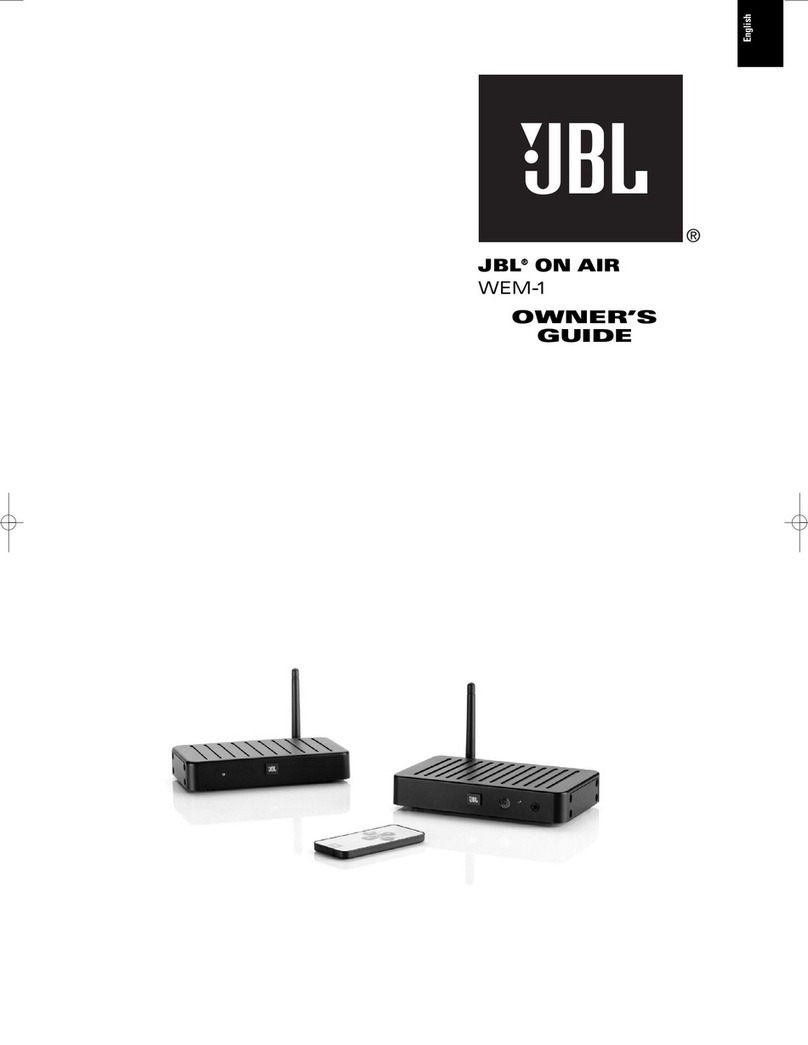
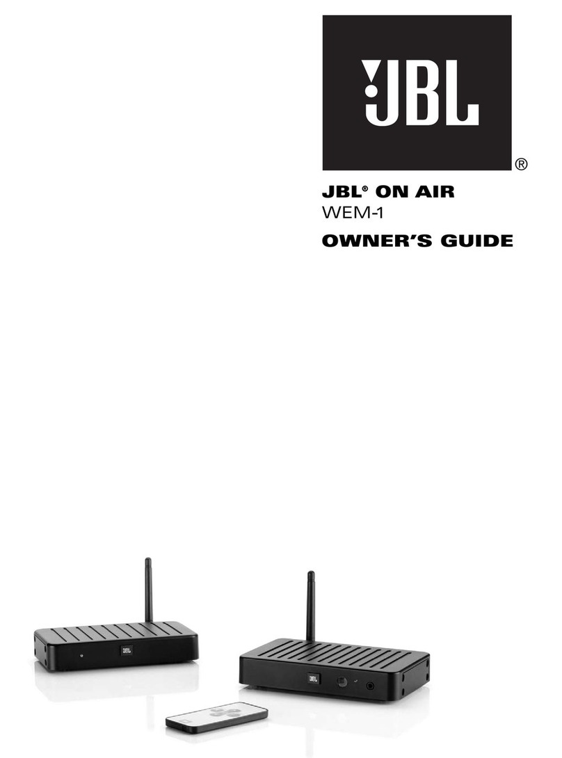
JBL WEM-1 User manual

JBL ON AIR™
WEM-1
Transmitter/Receiver/Amplifier
SERVICE MANUAL
JBL Consumer Products
250 Crossways Park Dr.
Woodbury, New York 11797 Rev111/2008

Service Note: WEM-1 systems should be exchanged under the warranty period;
the electronics are not serviceable down to component level.
Order the following parts when needed:
Mechanical parts see page 7
Transmitter part# 015-7600-00031-E
Receiver/Amplifier part# 010-7604-05194-E
- CONTENTS -
BASIC SPECIFICATIONS…………………….……………………..1
PACKAGING/ACCESSORIES……...…….………………………2
CONNECTIONS..…………………………….……………….. ….. 3
OPERATION………….…………………….……..….….………….5
EXPLODED VIEW, Transmitter and Receiver/Amplifier …..……7
WEM-1 BASIC SPECIFICATIONS
Frequency Range: 20Hz – 20kHz (+0dB, –1dB)
Amplifier Output: 50 Watts per channel
Signal-to-Noise Ratio: 80dBA
Operating Range: Up to 70' (22m), depending upon conditions
RF Operating Frequency: 2.4GHz
Power Requirement: 100V – 240V AC, 50/60Hz
Dimensions (H x W x D)
Transmitter Module: 1-1/8" x 6-3/16" x 4-5/8" (29mm x 158mm x 116mm)
3-3/4" (95mm) high with antenna extended
Receiver Module: 1-1/8" x 6" x 3-7/8" (29mm x 154mm x 98mm)
3-3/4" (95mm) high with antenna extended
Weight
Transmitter Module: 0.9 lb (0.4kg)
Receiver Module: 0.6 lb (0.3kg)
Occasional refinements may be made to existing products without notice but will always meet or exceed original
specifications unless otherwise stated
1
OnAirWEM-1

OnAirWEM-1
2

NOTES: For the sake of simplicity, throughout this manual the term “source”
is used when describing connections and operation. This would apply to any
device such as an A/V receiver, audio component, computer or portable
music player.
The JBL On Air WEM-1 may be connected to your source in several ways.
First, determine how you would like to use the WEM-1; then follow the setup
instructions for that application.
Audio sources that can be used in this application may be an A/V receiver or
audio receiver, a portable audio player, or a computer featuring a sound card.
First, determine whether your source contains RCA-type preamp outputs for
the front/main channels or only speaker wire outputs. On an A/V or audio
receiver, the preamp outputs are usually indicated by RCA-type jacks on
the back of the receiver labeled as “pre-out” (please refer to your source’s
owner’s manual to confirm whether it includes preamp outputs). If your source
includes these RCA-type outputs, follow the steps in Connection Option A.
If your source features only speaker wire outputs, follow steps in Connection
Option B. If your receiver does not feature either type of outputs for the
front/main channels, it cannot be used with the WEM-1.
Connection Option A
Connecting using the preamp outputs on your source:
NOTE: Make sure the power is turned off on all components.
Step 1.
Connect the interconnect cable (included) to the left and right front/main
preamp outputs, zone 2 outputs or REC outputs, and the inputs on the
transmitter module 7, as shown in Figure 1.
Figure 1.
Step 2.
Place the receiver module in the desired location in your home near an
AC outlet, as it needs to plug into the wall.
Step 3.
Connect speaker wire (not included) to the push terminals on the receiver
module Aand to the connectors on your speakers, as shown in Figure 2.
Please note that speaker wire features some form of a polarity indicator to
help distinguish its two conductors. Use this polarity indicator to ensure that
you are connecting the positive (+) terminal on one speaker to the positive (+)
terminal on the other, and the negative (–) to the negative (–).
Figure 2.
Step 4.
Plug the transmitter module and receiver module into the wall outlets, using
the power supply and correct power cord. Make sure the antennas 4E are
extended upward.
Step 5.
Make sure the ID Code setting on the transmitter 6is set to the same setting
as that on the receiver B. See page 5 for more information on ID codes. If
necessary, configure your receiver to activate the preamp level outputs for
the main/front channels (consult your source’s owner’s manual for specific
instructions).
When connected properly, the LED on the front of the receiver should be red
when first plugged in. When a button on the remote is pressed, the LED should
flash green until the transmitter and receiver “lock in.” It will then also light in
solid green. This LED will light in orange if the local input on the receiver is
selected (see page 5 under “Local Input” for more details).
Connection Option B
Connecting using the speaker-level outputs from your receiver:
NOTE: Make sure power is turned off on all components.
Step 1.
Connect the speaker wire to the receiver’s speaker outputs and the inputs
on the transmitter module 8, as shown in Figure 3.
Figure 3.
Step 2.
Place the receiver module in the desired location in your home near an
AC outlet, as it needs to plug into the wall.
Receiver
Right Speaker Left Speaker
RL
Source
Front/Main/Second Room
Preamp Outputs
CONNECTIONS
4
JBLP2744-WEM1-OM.qxd 9/30/08 1:27 PM Page 4
3
OnAirWEM-1

4
OnAirWEM-1

5
When using the WEM-1 to power surround speakers in
a home theater system:
In this application, the output level of your WEM-1 will not only be dependent
on the volume setting of your A/V source; it will also need to be properly
adjusted after installation and before use in order to be able to work correctly
with the other speakers in your multichannel surround system. To adjust the
output level, turn your A/V source on, set your A/V source’s volume control
about a third of the way up, and activate the speaker-level-adjustment test
tone. Make sure that the WEM-1 transmitter and receiver are on, both of the
speakers are connected, and there is RF lock (i.e., the LED on the receiver is
solid green). Using the remote control 1and 2, adjust the volume level of
the WEM-1 until its output level is balanced with the rest of the speakers in your
surround system. From this point on, you will not be using the WEM-1 remote
control for volume settings. You will be increasing and decreasing the output level
for the entire surround sound system using your A/V source’s volume control.
Please note that the WEM-1 will retain its volume setting when it is in standby,
so there is no need to set its volume level every time the system is turned on.
Local Input
The JBL On Air WEM-1 receiver module also includes a local input on the front
of the receiver module. This input allows you to hook up a portable audio player
directly to the WEM-1, wherever you may happen to be. For example, you could
have the system connected to your audio receiver, listening to a local FM station,
and then hook up your portable music player to the local input, switching
between the two different sources.
To connect a portable audio player to the receiver module, simply connect the
preamp-out, line-out or headphone jack to the line-in on the front of the receiver
module using a 1/8-inch mini-jack – 1/8-inch mini-jack cable (not included).
To switch between the two sources, push the Input button 3on the
remote control.
ID Codes
In the unlikely event that you experience interference when operating the
system, or if you have more than one set of WEM-1 transmitters and receivers
in operation, you may change the channel in which the system operates. On
both the transmitter and receiver modules, there is a four-position ID Code
selector 6B. Simply set each of the selectors to one of the other positions.
The transmitter and receiver must be set to the same position in order for the
system to function correctly. You can also set up a maximum of two receiver
modules to be receiving from the same transmitter by setting the channel
selector on the transmitter and the receiver to the same channel. Please
note that the two receiver modules need to be at least 10' (3m) apart, or
reception and operating range in one or both units may be degraded.
EQ Switch
The WEM-1 offers a choice of EQ positions for use with select JBL speakers.
This circuit optimizes the performance of the system when connected to the
loudspeakers indicated. If your specific loudspeaker is not listed below, simply
set the EQ Switch Cto position 1.
EQ Position Loudspeaker Model
1No EQ; use with any loudspeaker not listed below
2JBL CSB5
3JBL CST55
4JBL CS600 satellites
5JBL CS400 satellites
6JBL Control NOW,™JBL Control®Monitor
Step 3.
Connect the speaker wire to the push terminals on the receiver module A
and the terminals on the rear of your speakers, as shown in Figure 4. Please
note that the speaker wire features a polarity indicator to help distinguish its
two conductors. Use this polarity indicator to ensure that you are connecting
the positive (+) terminal on one speaker to the positive (+) terminal on the
other, and the negative (–) to the negative (–).
Figure 4.
Step 4.
Plug the transmitter module and receiver module into the wall outlets, using
the correct power supplies and power cords. Make sure the antennas 4E
are extended upward.
Make sure the ID Code setting on the transmitter 6is set to the same setting
as that on the receiver B. See the “ID Codes” section for more information
on ID codes. When connected properly, the LED on the front of the receiver
should be red when first plugged in. When a button on the remote is pressed,
the LED should flash green until the transmitter and receiver “lock in.” It will
then light in solid green. This LED will light orange if the local input on the
receiver is selected (see the “Local Input” section for more details).
Adjusting the Volume
Depending on the type of connection and the specific source that you are
using, the volume setting on your audio receiver may affect the sound output
level of your WEM-1. To check whether the output from your source is volume-
dependent, turn the volume level on your audio receiver to approximately
halfway. Turn on your WEM-1 transmitter and receiver modules. Once the LED
on the receiver module lights in solid green, indicating that RF lock has been
achieved, verify that there is sound output from the speakers. Then increase
and decrease the volume control on your receiver and observe whether this
affects the sound output from your speakers. If it does not, then the volume
control on your source unit can be set at any position that you may desire,
as it does not affect the performance of the WEM-1. If changing the volume
setting on your source does affect the output from the WEM-1, then you will
need to always keep your source’s volume control at about halfway up with audio
receivers or A/V receivers. From this point on, you will use the remote control
included with the WEM-1 to adjust Volume 1and 2.
Right Speaker Left Speaker
JBLP2744-WEM1-OM.qxd 9/30/08 1:27 PM Page 5
5
OnAirWEM-1

Auto On/Standby
The JBL On Air WEM-1 will automatically enter the Standby mode after approximately 10
minutes, when no signal is detected from your system. The WEM-1 will then power on instantly
when a signal is detected. When Mute is engaged, auto turn-off is deactivated.
Normal Operation (Input on Transmitter used)
LED Color Transmitter Module Receiver Module
Green Transmitter and receiver module
are communicating (RF lock) Transmitter and receiver module
are communicating (RF lock)
Blinking Green (Slow) Transmitter and receiver are
not communicating (no RF lock) Transmitter and receiver are
not communicating (no RF lock)
Blinking Green (Fast) Not applicable Receiving IR command from
remote control *
Red Standby (no signal being received) Standby (no signal being received)
Local input Used on Receiver
LED Color Transmitter Module Receiver Module
Orange Not applicable Local input is selected
Blinking Orange (Slow) Not applicable System muted
Blinking Orange (Fast) Not applicable Receiving IR command from
remote control *
* Blinking stops when unit reaches minimum or maximum volume setting
Subwoofer Output
The JBL On Air WEM-1 includes a subwoofer output _on the receiver module.
This output allows you to feed the low-frequency sounds to a separate powered subwoofer. A
powered subwoofer will deliver deeper bass response than is possible with speakers alone.
To connect a powered subwoofer to the receiver module, simply connect the
Sub Out _on the receiver module to the line-in on the rear of the powered
subwoofer, using a 1/8-inch stereo mini-jack/RCA cable (not included). Please
note that this output is full-range and not filtered or low-passed. Make sure that
your powered subwoofer features a low-pass crossover network and that this
crossover is indeed selected. Do not use the LFE input on a powered subwoofer,
as it is not filtered and you will be hearing a lot of undesirable higher-frequency
information from your subwoofer.
A Word About Wireless Products
The JBL On Air WEM-1 utilizes advanced wireless transceivers operating in the 2.4GHz
frequency band. This is the same frequency band that is used for wireless home networks and
high-quality cordless phones. It also allows the transmission of high-performance, full-spectrum
sound to remote locations, wirelessly.
Like all wireless devices, the WEM-1 wireless speaker’s operating range may vary, depending
upon variables such as building construction methods and materials, atmospheric conditions
and other sources of interference. Please consult your JBL dealer or distributor, or visit
www.jbl.com, for further information or assistance.
6
OnAirWEM-1

OnAirWEM-1
7
This manual suits for next models
1
Table of contents
Other JBL Microphone System manuals