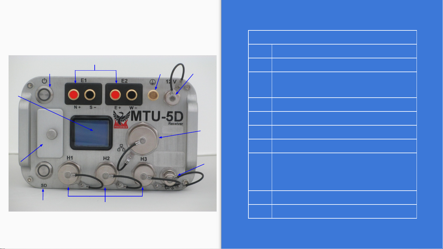
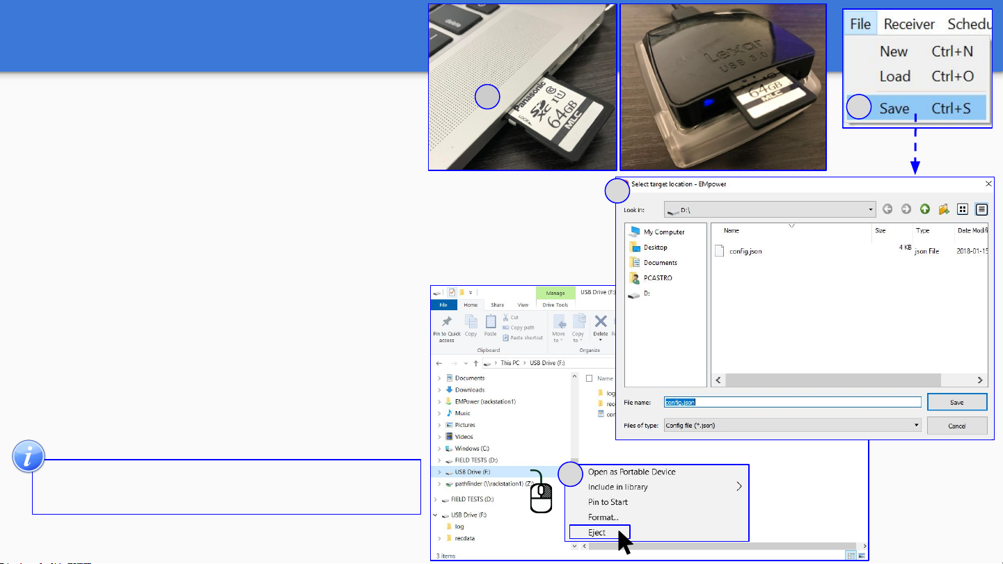
SD Card - Recording Data
1
Recording
1. Insert the SD card
2. To turn on the receiver, press the
Power button briefly
2.1. Wait until both LEDs are solid
blue
2.2. Automatic Start recording
*For any problem with the SD Card,
check the Troubleshooting manual
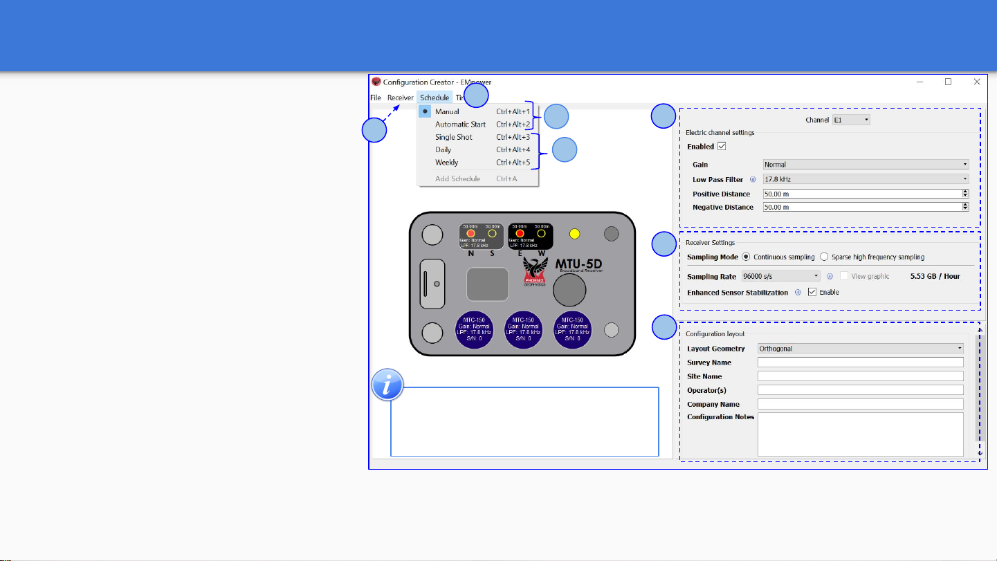
3. If the schedule type was
configured as Manual, press the
Power button to start recording
Press the power button briefly and
release
Starting Acquiring GPS Ready
SD
2
3Press the power button briefly and release
Ready Channels Recording
Detection
SD
Automatic Start
The recording starts automatically
according to the schedule
Recording
SD
2.1
2.2
Indicators
Rapid, equal pulses
Solid color / Off
9