manuals.online logo
Brands
  1. Home
  2. •
  3. Brands
  4. •
  5. Phoenix
  6. •
  7. Camera Accessories
  8. •
  9. Phoenix A10 User manual

Phoenix A10 User manual

Popular Camera Accessories manuals by other brands

CamRanger CamRanger user manual

CamRanger

CamRanger CamRanger user manual

Custom Brackets HDV CAGE KIT Instructions for use

Custom Brackets

Custom Brackets HDV CAGE KIT Instructions for use

Aegis ABL052010P user manual

Aegis

Aegis ABL052010P user manual

Saft SRA Series Installation and operating instructions

Saft

Saft SRA Series Installation and operating instructions

Kodak TIB5200 technical information

Kodak

Kodak TIB5200 technical information

Videotec HEG instruction manual

Videotec

Videotec HEG instruction manual

Ikelite 6171.11 manual

Ikelite

Ikelite 6171.11 manual

Pentax Auto Bellows Slide Copier K user manual

Pentax

Pentax Auto Bellows Slide Copier K user manual

Nikon UT-1 user manual

Nikon

Nikon UT-1 user manual

dji RONIN 4D quick start guide

dji

dji RONIN 4D quick start guide

SLIK ABLE 300DX user manual

SLIK

SLIK ABLE 300DX user manual

Rebelcell 36V70 user manual

Rebelcell

Rebelcell 36V70 user manual

Trojan GC2 48V quick start guide

Trojan

Trojan GC2 48V quick start guide

Calumet 7100 Series CK7114 operating instructions

Calumet

Calumet 7100 Series CK7114 operating instructions

Ropox 4Single Series User manual and installation instructions

Ropox

Ropox 4Single Series User manual and installation instructions

Cambo Wide DS Digital Series Main operating instructions

Cambo

Cambo Wide DS Digital Series Main operating instructions

Samsung SHG-120 Specification sheet

Samsung

Samsung SHG-120 Specification sheet

Ryobi BPL-1820 Owner's operating manual

Ryobi

Ryobi BPL-1820 Owner's operating manual

manuals.online logo
manuals.online logoBrands
  • About & Mission
  • Contact us
  • Privacy Policy
  • Terms and Conditions

Copyright 2025 Manuals.Online. All Rights Reserved.

1Copyright © 2013 Alary Design / PhotoShip One LLC - www.PhotoShipOne.com
USER MANUAL V1.00
2Copyright © 2013 Alary Design / PhotoShip One LLC - www.PhotoShipOne.com
Phoenix A10 Introduction
The Phoenix A10 is a digitally stabilized camera gimbal system. Phoenix A10 uses brushless DC motors for
each axis of pan, tilt, and roll. Stabilization is accomplished by a 3 axis AlexMOS (Basecam Electronics)
stabilization controller. The controller receives pitch/roll/yaw attitude data from a triaxial accelerometer/gyro
sensor that is located on the final driven axis of the Phoenix. The controller then processes the data and
sends power to each motor as required. This all happens quickly at about 100,000 times a second. The
result is a smooth and stable camera platform allowing for shots that have never before been possible with
larger, bulkier SteadiCam systems.
Brushless DC Motor Drive Systems
Brushless DC motor drive systems are a relatively new
technology as they pertain to small camera gimbal systems.
The first systems were in use around the first part of 2012.
Since then great advances in the technology have occurred.
The technology is advancing so quickly that what is written in
this manual now may be outdated by the time you read it.
What is a ‘brushless DC motor drive’ (BLDC)? BLDC motors
are also known as ‘electronically commutated motors’. They
differ from brushed DC motors because they do not have
carbon brushes that rub against a commutator bar. They are
powered by a DC voltage source run through copper field
windings that are switched on/off at high frequencies. The
switching of the voltage source is done at precise intervals to
create a rotating electromagnetic field (EMF). The rotating EMF causes the magnets on the motor rotor to
attract and repel to/from the EMF. This is known as electronic commutation. The result is precise motion of
the motor output shaft/rotor. The advantage of brushless motors over brushed motors is greater power
output, higher efficiency, lower electronic noise, ability to precisely commutate, and longer motor life.
BLDC motors are desirable for camera gimbals because they can be precisely driven and fast rotation rates.
The motors on the Phoenix A10 can sustain stabilization motions up to 140 degrees per second while
maintaining 0.1 degrees resolution. This allows for extremely precise stabilization motion control of the
camera, even in harsh motion environments such as aircraft or offroad vehicle use.
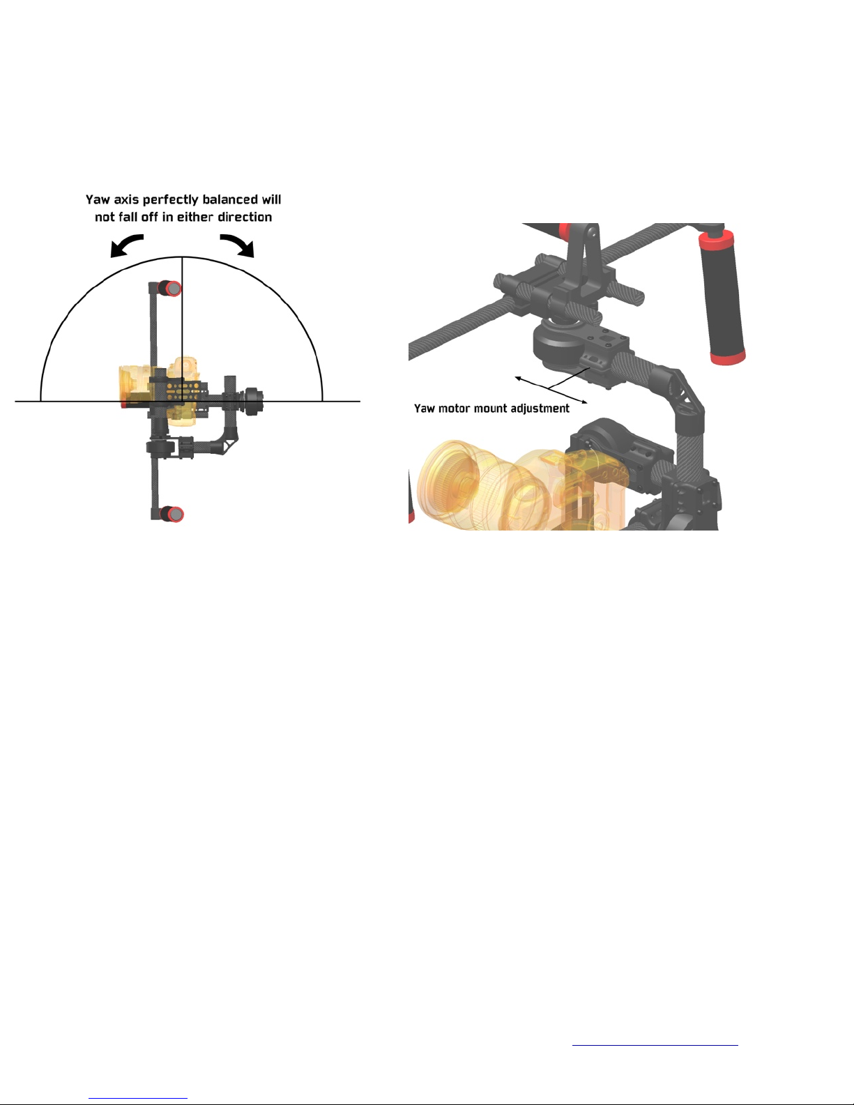
The extreme precision of BLDC motors does come at a cost, however. BLDC motors as they are used in
camera gimbals suffer from lack of torque. This means the motors have difficulty in operating in a precise
manner if the camera is not precisely balanced in the camera gimbal. A camera that is not properly
mounted in the gimbal can cause the motors to lose their ability to keep the camera in a stable attitude.
Any external forces acting upon the camera gimbal such as quick jolts, or fast motions will cause the motors
to ‘break loose’ and let the camera swing wildly. Provided the camera is balanced properly in the camera
gimbal the low torque issue with BLDC motors is minimized. A properly balanced camera gimbal system
can work quite effectively even with low torque BLDC motors.
Figure 1. Brushless DC Motor Windings & Magnets
3Copyright © 2013 Alary Design / PhotoShip One LLC - www.PhotoShipOne.com
Phoenix A10 Setup
Camera Size & Weight Limitations
Phoenix A10 is designed to be used with DSLR type cameras up to Canon 5D in size but will
work with smaller cameras like Sony NEX5,6,7 or similar.
Total camera weight with lens should be no less than 1.2lb (.68kg) or no greater than 4.75lb
(2.1kg) for best performance of Phoenix A10.
Physical size of camera should be limited to 6.5” wide, 5.25” tall, 8”
long for best performance. These dimensions can be exceeded
slightly (10% perhaps) but a decreased level of performance may
be expected. Keep in mind that most zoom lenses change length
considerably as the focal length gets longer. Phoenix A10 works
well at focal lengths
as long as 200mm.
Handheld Configuration Assembly
One of the most common configurations for Phoenix A10 is the
handheld configuration. Handheld allows Phoenix A10 to be
used in ‘run & gun’ type scenarios as well as used for aerial
work from airplane or helicopter. Due to A10 being compatible
with industry standard 15mm rod gear, it is easily assembled
into handheld configuration.
1) First, attach the 15mm rod mount to the top of the pan axle
flange on A10. Use M4x10 allen screws. Figure 4.
2) Next, slide the short 15mm rods through the rod mount.
Leave about 30mm of rods exposed on the front side.
Figure 5.
Figure 2. Camera Size Limitations
Figure 3. A10 in handheld configuration
Figure 4. 15mm rod mount attachment
4Copyright © 2013 Alary Design / PhotoShip One LLC - www.PhotoShipOne.com
3) Slide the top handle onto the rods behind the rod mount. Figure 6.
4) Now, slide the cross rod mount onto the front portion of exposed rods. Figure 7.
5) Slide the cross rod through the cross rod mount. Figure 8.
6) install the handles on the ends of cross rod. You may angle the handles to suit your comfort. Figure 9.
Figure 5. 15mm rods installed Figure 6. Top handle installed
Figure 7. Cross rod mount installed Figure 8. Cross rod installed
Figure 9. Handles installed
5Copyright © 2013 Alary Design / PhotoShip One LLC - www.PhotoShipOne.com
Shoulder Configuration
Shoulder configuration is setup similar to handheld as noted above. The same 15mm rod mount and
handles are used along with longer rods. The main difference being the Phoenix A10 is mounted on the
rods inverted, a 15mm rod shoulder pad is installed and a V-mount battery is mounted to the rear of the
rods for counter balance. it is important to note that in this mode the yaw axis setting in the software GUI
must be inverted. We will discuss that later in the manual.
Figure 10. Shoulder Configuration Assembled
6Copyright © 2013 Alary Design / PhotoShip One LLC - www.PhotoShipOne.com
Mechanical Balancing
Phoenix A10 will not work at all unless the camera is properly
balanced in the gimbal. There are several adjustments on the A10 that
allow for precisely locating the camera in all 3 axis. it is EXTREMELY
important that the balancing of the camera is carefully completed.
Camera balance is the key the operation of BLDC drive gimbals and
ignoring or incorrectly balancing the camera will cause the gimbal to
not function as designed (if at all).
The balancing is to be don on all 3 axis. Tilt, Roll and Pan. The
balance on tilt and roll must be perfect. The pan axis balance is less
critical. balancing is to be accomplished in the steps below.
Mount the camera to the camera mounting plate. Figure 11. Select a slot in the plate that best suits the
camera and allows the camera to balance on the tilt axis. The center of mass of the camera/lens should be
directly coincident with the tilt and roll axis rotation points. A line drawn through the roll axis converging with
the tilt axis must be 90 degrees perpendicular to the vertical tube on A10. If the tilt axis is more or less than
90 degrees from the vertical tube the camera will likely fall to the left or right side. Be sure the angle is at 90
degrees. Figure 12. Use the 1/4”-20 thumbscrew to attach camera to mounting plate.
Figure 12. Camera mounting alignment
Figure 11. Camera mounted to A10
7Copyright © 2013 Alary Design / PhotoShip One LLC - www.PhotoShipOne.com
If properly placed, the camera should remain in any angle you
position it. If you tilt the camera down and let it go it should
remain in that attitude. If it rotates up or down when let go you
will need to either adjust the camera fore/aft on the slotted
mounting plate or slide the mounting tube/camera vertically on
the vertical plate. To adjust vertically loosen the thumbnut on
the camera mounting tube and slide up or down on the slotted
plate. Figure 13.
The same applies to the roll axis. If properly balanced the
camera should remain at any angle after being placed there
and letting go. If it drops to one side or another the camera
needs to be moved left or right. There are two methods of
moving the camera left/right:
1) moving the ‘L’ arm left/right relative to the roll motor.
2) moving the camera mounting plate left/right on the camera mounting tube. This is done by loosening the
camera mounting plate clamps and sliding the mounting plate along the mounting tube. Do not over-
tighten the clamps. The clamps do not require much torque on the clamp screws. Figure 14.
It’s important to keep the camera optical center as close to the roll axis as possible. Do this by keeping the
camera as close to the tilt motor as possible. Figure 15.
Figure 13. Vertical camera adjustment
Figure 15. Optical center alignment
Figure 14. Mounting plate adjustment
8Copyright © 2013 Alary Design / PhotoShip One LLC - www.PhotoShipOne.com
The yaw axis is balanced next. Yaw axis may not be able to bet set to a perfect balance and in most
cases that will not present a major problem. Just balance the yaw axis as closely as you are able.
The yaw axis is balanced by orienting the A10 on it’s side. When properly balanced the yaw axis will
remain in any orientation you place it in without falling over to one side or another. Figure 16.
Figure 16. Yaw axis balancing
Adjusting the yaw axis balance is accomplished by moving the yaw motor assembly fore/aft on the
horizontal tube. There is a limited amount of movement that can be done without the tube rubbing
against the motor. Cameras lighter than 2.0lb (0.9kg) may not be able to be perfectly balanced in the
yaw axis due to the physical layout/geometry of the A10. As previously mentioned, it is only important
to get the balance as close as possible.
Figure 17. Yaw motor adjustment
Focal Length Changes
Most zoom lenses will extend when the focal length is adjusted higher. This will cause an imbalance in
the tilt axis. Phoenix A10 is tolerant of moderate changes in focal length but it is best to adjust for tilt
balance at a midpoint of the focal length you know you will be using. For instance, if you know you will
be shooting between 20-75mm it would be best to complete the tilt axis balancing with the lens set to
about 48mm.
We have found Phoenix A10 to work quite well at focal lengths as long as 200mm provided the total
camera/lens weight is kept under about 4.75lb.
9Copyright © 2013 Alary Design / PhotoShip One LLC - www.PhotoShipOne.com
Controller Case Connections
The stabilization controller case has several ports for connections to motors, USB, as well as a function
button on the side. There are two different cases depending on which controller is used. We use the
ArmBGC v3.0 controller and the Flyduino/Viacopter controller.
There is no difference in performance between the two but each requires a different case design due to
port/button locations on the circuit boards.
You can identify the case you have by looking at the images below.
The USB Micro port is on the bottom end of both cases.
Figure 19. USB Port on controller
10 Copyright © 2013 Alary Design / PhotoShip One LLC - www.PhotoShipOne.com
AlexMOS Stabilization controller.
The Phoenix A10 uses the AlexMOS 3 axis stabilization controller
by Basecam Electronics to provide stabilization. Adjustment and
tuning of the controller is done by a graphical user interface (GUI)
utility. Figure 18. The GUI is run from a PC (.exe file) or Mac (.jar
file). The GUI will allow you to adjust many control and
stabilization parameters. Each individual camera/lens combination
you may use will require slight tuning adjustments to the PID gain,
power, and follow mode parameters within the GUI You can
download and review the AlexMOS manual and GUI software
here:
http://www.simplebgc.com/eng/downloads/
Figure 18. GUI Utility Screenshot
Connection of the controller to the GUI is done by a USB Micro port on the bottom of the controller
case. Figure 19. For more details on tuning the controller with the GUI please check out a great article
by Aerial Pixels located here:
http://www.aerialpixels.com/support/alexmos-brushless-gimbal-controller-simplebgc-tuning-guide/
Shoulder Rig Yaw Motor ‘Invert’ Setting.
When the A10 is configured in shoulder rig mode the yaw motor ‘invert’ setting must be checked in the
GUI. This is required because the A10 must be inverted when run in shoulder rig configuration. This
causes the yaw axis to be reversed. If you do not check the ‘invert’ setting the yaw axis will wander left
and right.
Figure 20. Yaw Motor Invert