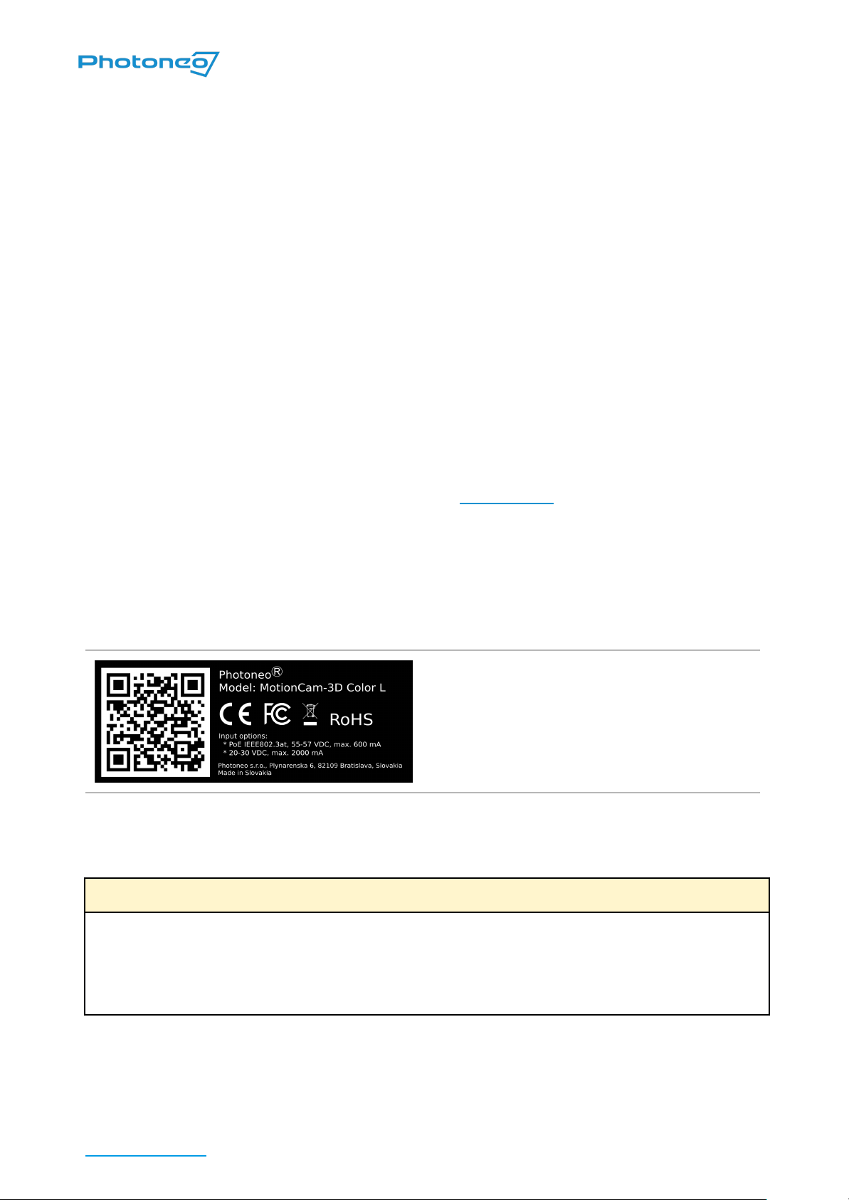
Laser radiation warning with laser class label. The serial number of the
device can be found above the warning labels.
Label specifying wavelength, average power, pulse energy and pulse
length of the laser.
Laser radiation warning with laser class label. The serial number of the
device can be found above the warning labels.
Label specifying wavelength, average power, pulse energy, and pulse
length of the laser.
Objects Suitable for Scanning
Photoneo 3D sensors are measurement devices working on the principle of optical triangulation.
Modulated light projected from the projection unit is reflected by the scanned object and captured
by a camera unit based on which the distance to the object is computed.
For PhoXi 3D Scanners, which work on the principle of sequential structured light, the scene
must be completely static during the scan.
For MotionCam-3D (Color), which uses the revolutionary and patented principle of Parallel
Structured Light™, the scene can be in arbitrary movement or vibration.
As both systems rely on the reflection of projected light, objects most suitable for scanning are
(including and not limited to):
■rough surface objects, for example, wood, rubber, paper, plaster, etc.
■objects with a matte finish, such as sand-blasted aluminum, cast iron, etc.
■molded, un-polished plastic materials
support@photoneo.com Photoneo 3D sensors - User Manual 9/42