Physik Instrumente E-509 Series User manual

Artisan Technology Group is your source for quality
new and certied-used/pre-owned equipment
• FAST SHIPPING AND
DELIVERY
• TENS OF THOUSANDS OF
IN-STOCK ITEMS
• EQUIPMENT DEMOS
• HUNDREDS OF
MANUFACTURERS
SUPPORTED
• LEASING/MONTHLY
RENTALS
• ITAR CERTIFIED
SECURE ASSET SOLUTIONS
SERVICE CENTER REPAIRS
Experienced engineers and technicians on staff
at our full-service, in-house repair center
WE BUY USED EQUIPMENT
Sell your excess, underutilized, and idle used equipment
We also offer credit for buy-backs and trade-ins
www.artisantg.com/WeBuyEquipment
REMOTE INSPECTION
Remotely inspect equipment before purchasing with
our interactive website at www.instraview.com
LOOKING FOR MORE INFORMATION?
Visit us on the web at www.artisantg.com for more
information on price quotations, drivers, technical
specications, manuals, and documentation
Contact us: (888) 88-SOURCE | sales@artisantg.com | www.artisantg.com
SM
View
Instra

© Physik Instrumente (PI) GmbH & Co. KG
Auf der Römerstr. 1 ⋅76228 Karlsruhe, Germany
Tel. +49-721-4846-0 ⋅Fax: +49-721-4846-299
PZ 77E User Manual
E-509TTPosition Servo-Control Module
Release: 2.8.4 Date: 2009-02-20
TThis document describes the
following product(s):
TE-509.LxT
Position Servo-Control Module for LVDT sensor
TE-509.SxT
Position Servo-Control Module for SGS
TE-509.CxAT
Position Servo-Control Module for Capacitive
sensors
TE-509.E3T
Position Servo-Control Module for Single-Plate
PISeca™ Capacitive Sensors
TE-509.E03T
Signal Conditioner for Single-Plate PISeca™
Capacitive Sensors
Artisan Technology Group - Quality Instrumentation ... Guaranteed | (888) 88-SOURCE | www.artisantg.com

Artisan Technology Group - Quality Instrumentation ... Guaranteed | (888) 88-SOURCE | www.artisantg.com

Physik Instrumente (PI) GmbH & Co. KG is the owner of the following company names and
trademarks:
PI®, PIC®, PICMA®, PILine®, PIFOC®, PiezoWalk®, NEXACT®, NEXLINE®, NanoCube®,
NanoAutomation®
Copyright 1999–2009 by Physik Instrumente (PI) GmbH & Co. KG, Karlsruhe, Germany.
The text, photographs and drawings in this manual enjoy copyright protection. With regard
thereto, Physik Instrumente (PI) GmbH & Co. KG reserves all rights. Use of said text,
photographs and drawings is permitted only in part and only upon citation of the source
First printing X2009-02-20X
Document Number XPZ 77EX, Eco, Bro, Release X2.8.4X
E-509_User_PZ77E284.doc
Subject to change without notice. This manual is superseded by any new release. The newest
release is available for download at Hwww.pi.wsH.
Artisan Technology Group - Quality Instrumentation ... Guaranteed | (888) 88-SOURCE | www.artisantg.com

TAbout This Document
Users of This Manual
This manual is designed to help the reader to install and operate the XE-509XXPosition Servo-
Control ModuleX. It assumes that the reader has a fundamental understanding of basic servo
systems, as well as motion control concepts and applicable safety procedures.
The manual describes the physical specifications and dimensions of the XE-509XXPosition Servo-
Control ModuleXas well as the procedures which are required to put the associated motion
system into operation.
This document is available as PDF file. Updated releases are available from HTUwww.pi.wsUTH or
Conventions
The notes and symbols used in this manual have the following meanings:
CAUTION
Calls attention to a procedure, practice, or condition which, if not
correctly performed or adhered to, could result in damage to
equipment.
NOTE
Provides additional information or application hints.
Related Documents
The other system components and any software tools which might be delivered with XE-509X
XPosition Servo-Control ModuleXare described in their own manuals. All documents are available
as PDF files from Hwww.pi.wsHor by email from your Physik Instrumente Sales Engineer or
HTU[email protected]UTH.
!
Artisan Technology Group - Quality Instrumentation ... Guaranteed | (888) 88-SOURCE | www.artisantg.com

E-509 Position Servo-Control Module User Manual PZ 77E
Release 2.8.4 www.pi.ws Page 5
Contents
1. Introduction................................................................. 6
1.1. Safety Precautions ..................................................................... 6
1.2. Prescribed Use ............................................................................ 7
1.3. Model Survey ............................................................................... 7
1.4. Front Panels................................................................................. 9
2. Quick Start................................................................... 9
3. E-509 Design.............................................................. 11
3.1. Signal Path Diagram .................................................................. 12
3.2. Submodules ............................................................................... 13
3.3. Sensor Processing and Servo-Control Functions ...................... 14
4. E-509 Calibration Routines....................................... 15
4.1. Static Calibration........................................................................ 15
4.2. Dynamic Calibration................................................................... 19
4.3. Adjustment for Systems with E-509.Ex PISeca™ Models ......... 19
5. Disposal..................................................................... 22
6. E-509 Technical Data ................................................. 23
6.1. Two-Plate Cap. Sensor on-board Sensor Processing ........... 25
6.2. Single-Plate Cap Sensor on-board Sensor Processing ............. 27
7. Pin Assignments........................................................ 30
7.1. 32-Pin Main Connector, DIN 41612 ........................................... 30
7.2. SENSOR-MONITOR Output ...................................................... 31
7.3. Sensor Connections................................................................... 33
8. Appendix—Single-Plate PISeca™ Capacitive Sensors36
8.1. Measuring Principle ................................................................... 36
8.2. Measurement Range ................................................................. 37
8.3. Bandwidth .................................................................................. 37
8.4. Linearity ..................................................................................... 37
8.5. Target Plane .............................................................................. 38
8.6. Terminology ............................................................................... 38
Artisan Technology Group - Quality Instrumentation ... Guaranteed | (888) 88-SOURCE | www.artisantg.com

E-509 Position Servo-Control Module User Manual PZ 77E
Release 2.8.4 www.pi.ws Page 6
1. Introduction
E-509 is a displacement-sensor and position-servo-control module for PZT
actuators. The module is used in the E-500-series electronics and allows
controlling the position (displacement) of piezoelectric devices with nanometer
resolution. It can also be installed in E-470, E-471, E-480 and E-481 high-voltage
amplifier systems, giving them servo-control capability.
The E-509 controller generates the input signal for the power amplifier module
which actually drives the PZT. The E-509 uses the difference between target
position and the actual position in a servo-loop algorithm, compensating drift and
hysteresis of the PZT actuators. The effective stiffness of the actuator is
significantly increased due to the rapid displacement control effected by adjusting
the PZT operating voltage so as to maintain the displacement even when external
forces change.
Position information is provided by high-resolution sensors integrated in the
mechanical stage or PZT actuator. Strain gauge sensors (SGS), LVDT sensors
and capacitive sensors are supported by the E-509.
The E-509 does not encompass an amplifier to supply the PZT operating voltage.
High-voltage (E-507, E-508, E-470, E-471, E-480, E-481) or low-voltage amplifiers
(E-503, E-505) can be used—the choice depends on the PZT type. The E-509 and
amplifier are installed in the same chassis and communicate automatically over the
backplane (see signal path diagram, p. X12X).
The main parts of the E-509 are the sensor signal processing circuit and a servo-
controller with adjustable P-I filter and optional notch filter to allow operation close
to the mechanical resonant frequency.
The E-509 hardware design comprises the basic PCB module and one or two
small PCB submodules for each channel. Implemented on submodules are the
servo-control algorithms, and, in the case of SGS and LVDT sensor versions, the
sensor processing.
1.1. Safety Precautions
CAUTION—Electrostatic Hazard
Electronic components are sensitive to electrostatic electricity. Take appropriate electrostatic
protection measures when installing or removing boards or working on an open controller.
CAUTION—High Voltage
The piezo amplifiers used with this product are high-voltage devices capable of generating high
output currents. They may cause serious or even lethal injury if used improperly.
Take special care if connecting products from other manufactures.
CAUTION—Avoid Resonance Damage
Most of the PZT actuators used with the system described in this manual can be permanently
damaged by uncontrolled resonance. The system must never be operated too close to the
resonant frequency. If you hear or see resonant behavior, switch off the unit.
!
!
!
Artisan Technology Group - Quality Instrumentation ... Guaranteed | (888) 88-SOURCE | www.artisantg.com

E-509 Position Servo-Control Module User Manual PZ 77E
Release 2.8.4 www.pi.ws Page 7
1.2. Prescribed Use
Based on their design and realization, XE-509Xmodules are intended to be used
installed in compatible housings, like the PI E-500/E-501 series chassis. They
must not be used for applications not in conformance with this manual.
Observe the safety precautions given in this User Manual.
XE-509Xsystems conform to Measurement Category I (CAT I) and may not be used
for Measurement Categories II, III or IV. Other use of the device (i.e. operation
other than instructed in this Manual) may affect the safeguards provided.
Standard XE-509Xsystems are designed to operate under normal ambient conditions
at least as listed here. More stringent conditions given in the Specifications Table
(p. X23X) are, of course, also met.
Indoor use
Altitude up to 2000 m
Temperature range 5°C to 40°C
Max. relative humidity 80% for temperatures up to 31°C, decreasing linearly to 50%
relative humidity at 40°C
Line voltage fluctuations not greater than ±10% of the line voltage
Transient overvoltages as typical for public power supply
TNote: The nominal level of the transient overvoltage is the standing surge voltage according to the overvoltage category
II (IEC 60364-4-443).T
Degree of pollution: 2
1.3. Model SurveyTPF
1
FPT
E-509.S1 PZT Servo-Control Module, one channel, for strain gauge sensors
E-509.S3 PZT Servo-Control Module, three channels, for strain gauge sensors
E-509.L1 PZT Servo-Control Module, one channel, for LVDT sensors
E-509.L3 PZT Servo-Control Module, three channels, for LVDT sensors
E-509.C1A PZT Servo-Control Module, one channel, for 2-plate capacitive sensors
E-509.C2A PZT Servo-Control Module, two channels, for 2-plate capacitive sensors
E-509.C3A PZT Servo-Control Module, three channels, for 2-plate capacitive sensors
E-509.E3 PZT Servo-Control Module, three channels, for single-plate PISeca™
capacitive sensors
E-509.E03 Signal conditioner (sensor excitation and readout) module, three channels,
for single-plate PISeca™ capacitive sensors; no servo-control
TP
1
PT Most SGS and LVDT versions cannot be distinguished by the front panel.TP
PT
Artisan Technology Group - Quality Instrumentation ... Guaranteed | (888) 88-SOURCE | www.artisantg.com

E-509 Position Servo-Control Module User Manual PZ 77E
Release 2.8.4 www.pi.ws Page 8
1.3.1. Submodules (pre-installed on the E-509TPF
2
FPT)
E-801.1x Sensor-processing submodule for SGS sensors (present on E-
509.Sx/E-509.S3S)
E-801.2x Sensor-processing submodule for LVDT sensors (present on E-509.Lx)
E-802.5x Position Servo-Control submodule (present on all except E-509.E03)
The submodules are described in separate manuals: E-801 submodules in
PZ117E, E-802.55s in PZ150E, and all former E-802.5x versions in PZ113E. The
appropriate manuals are included with your E-509 module(s).
1.3.2. Standard Accessories
E-808.90 Sensor-Monitor cable: comes with three-channel SGS- and LVDT-
sensor versions (E-509.S3, E-509.L3)
Note: The purpose of this cable is simply to split up the SENSOR
MONITOR output signal (LEMO) for the three channels. The
leads of this open ended cable are color coded:
white = channel 1,
brown = channel 2,
green = channel 3,
shield = GND.
D-893.32 Sensor-Monitor cable: comes with each capacitive-sensor version
(E-509.CxA, E-509.Ex)
Note: The purpose of this cable is simply to split up the SENSOR
MONITOR output signal (6-pin LEMO) to three separate BNC
connectors. The cable is also specially designed for low-noise
operation. The BNC connectors are each labeled with the
channel number.
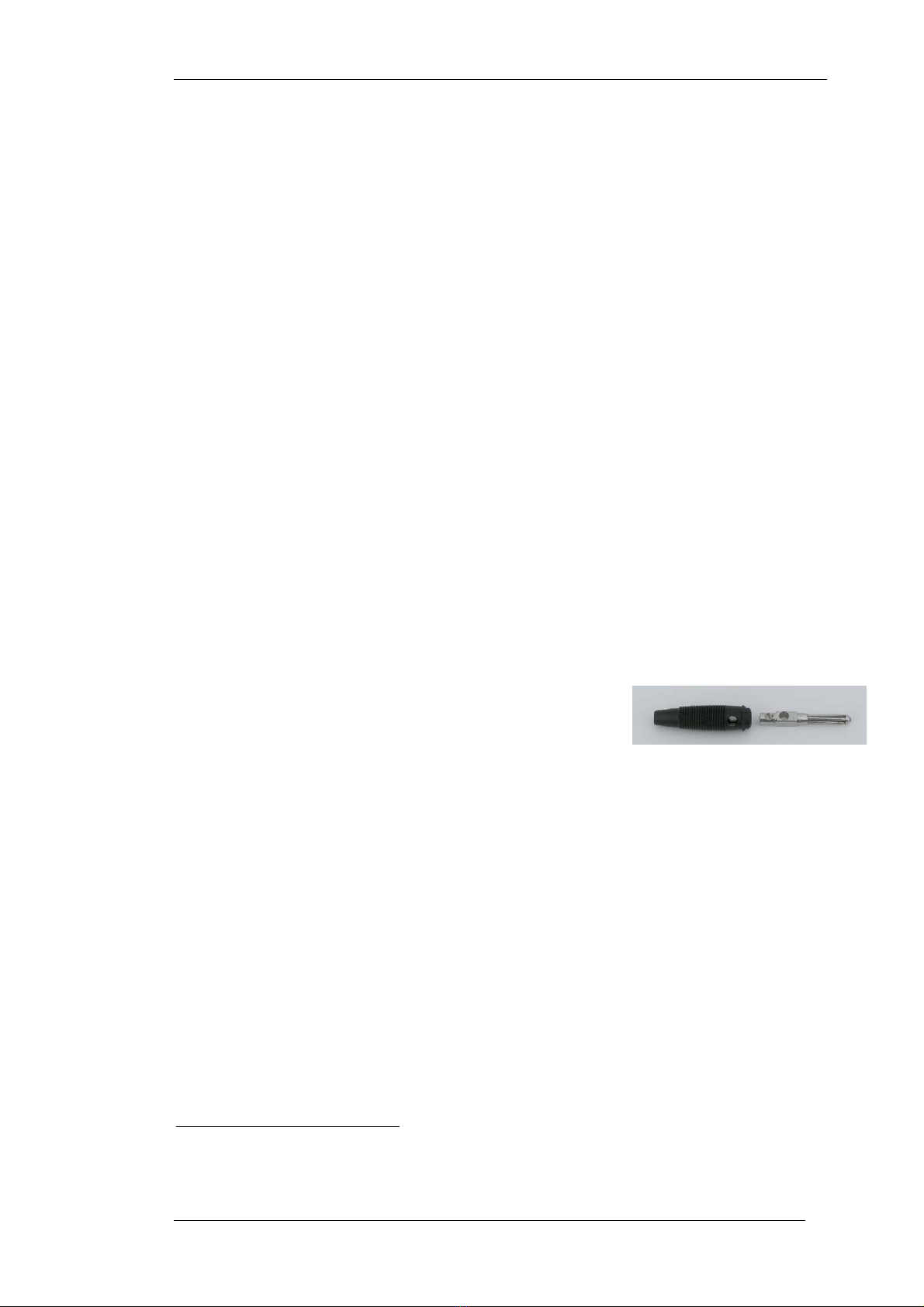
3214 Banana Plug: For single-plate PISeca™
capacitive sensor reference plane ground
connection. Shown at right disassembled,
before installation of lead. Fig. 1: Banana plug
1.3.3. Single-Plate Capacitive Sensor Probes
Different size sensors are available for the E-509.E03 and E-509.E3 single-plate
capacitive sensor versions. The sensors must thus be ordered separately:
D-510.020 PISeca™ Single-Electrode Capacitive Sensor Probe, 8 mm
diameter, 20 µm nominal range, 40 µm, 50 µm and 100 µm
extended ranges, D-891.01E connecting cable included
D-510.050 PISeca™ Single-Electrode Capacitive Sensor Probe, 12 mm
diameter, 50 µm nominal range, 100 µm, 125 µm, 250 µm
extended ranges, D-891.01E connecting cable included
D-510.100 PISeca™ Single-Electrode Capacitive Sensor Probe, 20 mm
diameter, 100 µm nominal range, 200 µm, 250 µm, 500 µm
extended ranges, D-891.01E connecting cable included
See the sensor documentation for information on mounting and performance.
TP
2
PT For versions and details of the submodules, refer to the E-801 Sensor Submodule User Manual (PZ 117E)
and the E-802 User Manual (PZ150E or PZ 113E). The E-509.CxA and E-509.Ex have sensor-processing
electronics on the main module
Artisan Technology Group - Quality Instrumentation ... Guaranteed | (888) 88-SOURCE | www.artisantg.com

E-509 Position Servo-Control Module User Manual PZ 77E
Release 2.8.4 www.pi.ws Page 9
1.4. Front Panels
ON
OFF
SENSOR
PZT-SERVO
CONTROLLER
SERVO
OFL
SENSOR
MONITOR
ZERO
E-509
Fig. 2: LVDT and SGS versions
share the same front panels Fig. 3: Typical front panels of the different
capacitive sensor versions*
*The predecessors of E-509.CxA models were E-509.Cx; they differ in SENSOR
MONITOR socket.
2. Quick Start
NOTE
To achieve optimum measurement stability it is recommended to wait at least 30 minutes after
powering up the system.
2.1.1. General Procedure
This quick start assumes that your E-509 was ordered with an appropriate chassis
and was calibrated at the factory with the PZT actuators with which it will be
operated. To put the system into operation, proceed as follows:
1. Make sure the control unit in which the E-509 is installed is powered down.
2. Connect the PZT actuator sensor cables to the E-509 servo-controller. With
single-plate capacitive sensor systems, see Section X2.1.2Xbelow. On multi-
channel units, make sure that each PZT is connected to the channel with which
it was calibrated (see label affixed to back of chassis). On 2-plate capacitive
sensor systems, make sure that the “Probe” and “Target” sensor cables are not
interchanged.
Artisan Technology Group - Quality Instrumentation ... Guaranteed | (888) 88-SOURCE | www.artisantg.com

E-509 Position Servo-Control Module User Manual PZ 77E
Release 2.8.4 www.pi.ws Page 10
3. Connect the PZT voltage supply cables to the power amplifier module (in the
same chassis, near the E-509). Again, in multi-axis systems, make sure the
proper PZTs are connected to the proper channels.
CAUTION—High Voltage
The piezo amplifiers used with this product are high-voltage devices capable of generating high
output currents. They may cause serious or even lethal injury if used improperly.
Take special care if connecting products from other manufactures.
CAUTION—Avoid Resonance Damage
Most of the PZT actuators used with the system described in this manual can be permanently
damaged by uncontrolled resonance. The system must never be operated too close to the
resonant frequency. If you hear or see resonant behavior, switch off the unit.
4. If you have a computer control and/or display module in the system (e.g. E-516
or E-517), consult its User Manual for information on commanding the system
and setting servo-control parameters. In particular, make sure the front-panel
Servo-Control switch is properly set for the type of operation you require.
5. Power up the system. If you see or hear resonant behavior, power down
immediately and check the servo-control parameters. See the “XDynamic
CalibrationX” Section on p. X19Xfor more information.
2.1.2. Systems with E-509.Ex PISeca™ Models
NOTE
Motion of the connecting cable should be avoided because of capacitive influences. If possible,
the application should be designed with sensor probe always at rest and the target the moving
part of the system.
1. Mount the sensor probe in your intended application as described in the
Technical Note D510T0001. Note that the minimum allowable probe-to-target
gap is 10 µm. A minimum gap of 15 µm is recommended.
CAUTION
Take care not to shift the sensor probe when connecting the cable!
2. Connect the sensor probe to the Sensor In socket of the E-509.Ex electronics
unit using the D-891.01E cable (comes with the sensor). Make sure that each
sensor probe is connected to the channel with which it was calibrated (see
label affixed to back of chassis)
3. Connect the target surface to the Sensor Gnd socket on the front of the E-
509.Ex (mating banana plug included). Make sure that each target surface is
connected to the channel with which the corresponding sensor probe was
calibrated (see label affixed to back of chassis)
!
!
!
Artisan Technology Group - Quality Instrumentation ... Guaranteed | (888) 88-SOURCE | www.artisantg.com

E-509 Position Servo-Control Module User Manual PZ 77E
Release 2.8.4 www.pi.ws Page 11
4. Connect the included E-808.90 sensor monitor cable to the Sensor Monitor 1-
3 socket. The sensor monitor signal shows the current position of the sensor
probe in relation to the target and the selected measurement range. See
Section X4.3.3Xfor details on how to adjust target surface and probe
3. E-509 Design
The E-509 module is designed to plug into a compatible PI chassis (e.g. E-500, E-
501 or E-470, but not E-50x.621). There it operates in conjunction with other
modules such as power amplifiers and display or remote control units. See the
E-500/E-501 User Manual (PZ 62E) and the manuals of other devices in your
system for details. Most questions about E-509 operation can be answered by
reference to the signal path diagram in the next section.
Artisan Technology Group - Quality Instrumentation ... Guaranteed | (888) 88-SOURCE | www.artisantg.com

E-509 Position Servo-Control Module User Manual PZ 77E
Release 2.8.4 www.pi.ws Page 12
3.1. Signal Path Diagram
Fig. 4: Signal path (only one channel shown) in a system with an E-509 Servo-
Controller, a PZT power amplifier and an E-516 Computer Interface and Display
Module. Note that "Control In" and "DC-offset" on the amplifier module do not
control the amplifier directly, but only determine “Control Out” for the other
modules. Some amplifiers can invert these signals, and the E-509 output can be
inverted or shifted, but if Servo is ON, the E-509 “Target In” must be in the 0 to
10 V range if Servo is ON. Note also that the E-802 servo mode is determined by a
combination of the toggle switch position and the state commanded by the E-516.
Note that E-517 Interface and Display modules act in the same way as E-516s.
Artisan Technology Group - Quality Instrumentation ... Guaranteed | (888) 88-SOURCE | www.artisantg.com

E-509 Position Servo-Control Module User Manual PZ 77E
Release 2.8.4 www.pi.ws Page 13
3.2. Submodules
Some functions of the E-509 are implemented on plug-in submodulesTPF
3
FPT, as
discussed in the following sections. It should not be necessary to remove or
replace the submodules, but if you ever do so, be sure to face the component
sides as illustrated, (XFig. 5X).
SGS and LVDT Versions Capacitive Sensor Servo Versions
Fig. 5: Submodule locations on E-509 modules. Note also sensor gain
potentiometer locations
3.2.1. E-509.S1 and E-509.L1
These single-channel versions have one servo-control and sensor submodule
each. The submodules location is identical with the layout shown in XFig. 5X, but only
for one channel each.
3.2.2. E-509.S3 and E-509.L3
These 3-channel versions are depicted at left in XFig. 5X, and have three servo-
control and three sensor submodules each.
3.2.3. E-509.CxA and E-509.E3
The E-509.CxA and E-509.E3 versions also have one servo-control submodule per
channel. The sensor processing electronics is implemented on the main board
rather than on a submodule (XFig. 5Xright).
See XFig. 9Xon page X25Xfor the full layout of a three-channel E-509.C3A or XFig. 11X
on p. X28Xfor the E-509.E3.
3.2.4. E-509.E03
The E-509.E03 does sensor processing only and has no servo-controller and no
submodules. Its layout is otherwise the same as the E-509.E3 (XFig. 11X).
TP
3
PT Except on the E-509.E03 which has no servo-controller and no submodules.
Artisan Technology Group - Quality Instrumentation ... Guaranteed | (888) 88-SOURCE | www.artisantg.com

E-509 Position Servo-Control Module User Manual PZ 77E
Release 2.8.4 www.pi.ws Page 14
3.3. Sensor Processing and Servo-Control Functions
The E-509 modules normally come pre-installed in an appropriate PI chassis
(except for OEM versions). The system is calibrated at the factory with the
associated PZT actuators.
If, however, you should need to recalibrate your system, see Section X4Xand the E-
802 Servo-Control Submodule User Manual.
3.3.1. Sensor Processing Electronics
SGS versions have E-801.1x submodules which provide DC sensor excitation and
readout.
LVDT versions have E-801.2x submodules which provide AC sensor excitation.
They can also be connected to SGS sensors if necessary. On multi-channel E-
509s, the LVDT excitation frequencies are synchronized by the appropriate use of
master and slave E-801.2x versions or jumper settings.
Should you ever need to make any adjustments on the sensor submodules, refer
to the E-801 User Manual for more details.
Capacitive sensor versions have the sensor electronics on the E-509. See Section
X6.1Xor X6.2Xof this manual for details.
3.3.2. E-802 Position Servo-Control Submodules
The E-802 submodule processes the control signal for the amplifier driving the piezoelectric
translators. Slew rate limitation, notch filter and servo-control loop are all implemented on
the E-802.
The servo-loop logic compares the TARGET IN and the sensor signal (current position) to
generate the SERVO-CONTROL OUT amplifier control signal using an analog proportional-
integral (P-I) algorithm. For details see the signal path diagram, XFig. 4X, on X12X.
The E-802 can operate in either servo OFF mode or servo ON mode. The mode is
determined by a combination of the (active-low) SERVO ON/OFF signal and the front-panel
SERVO TOGGLE SWITCH: for servo OFF mode, both must be in the OFF condition (see
Signal Path diagram, p. X12X). With the E-802.55 and higher versions of the E-802, the notch
filter and slew rate limiter remain active even when servo-mode is OFF. This can cause a
±5% shift of the open-loop output voltage to occur when the notch filter frequency is
changed.
For more details and calibration procedures, see Section X4Xand the E-802 Servo-Control
Submodule User Manual.
Artisan Technology Group - Quality Instrumentation ... Guaranteed | (888) 88-SOURCE | www.artisantg.com

E-509 Position Servo-Control Module User Manual PZ 77E
Release 2.8.4 www.pi.ws Page 15
4. E-509 Calibration Routines
For most applications, only the zero point has to be realigned from time to time to
compensate for temperature changes. Further adjustments are not required and
not recommended as long as system components are not exchanged or modified.
NOTE
All basic calibration adjustments are done in PI lab before shipment. The PZT system is
delivered ready for operation. Except for occasional zero-point adjustment, it should not be
necessary to calibrate the system.
Therefore calibration should only be done if the controller/actuator configuration is
changed or elements are replaced.
The full calibration and adjustment procedure for the E-509 Position Servo-Control
Module includes static calibration (zero point and sensor gain adjustment) and
dynamic calibration (servo-loop, slew rate and step response). In addition, on the
capacitive sensor versions, the ILS (integrated linearization system) can be
adjusted to minimize 2nd order polynomial non-linearities.
Calibration must be performed separately on each channel.
NOTE
The PZT actuator is calibrated in conjunction with a particular E-509 control module: the
devices then belong together. Replacement of either one or the other requires new calibration
runs to obtain the specified system accuracy.
4.1. Static Calibration
Proper static calibration makes it possible to accurately drive the PZT system to
absolute positions with an external analog control signal running over a 10 V range
and without reaching the output voltage limits of the amplifier and causing overflow
conditions.
Static calibration consists of zero-point adjustment and static gain adjustment—
and for capacitive sensor versions—ILS adjustment. The adjustments are to some
degree interdependent and should be repeated until stable settings are obtained.
NOTE
Zero-point adjustment is the only calibration operation regularly required in most application
environments.
The following subsections describe the static calibration procedure for one
channel. Note that calibration must be performed separately on each channel.
4.1.1. Equipment Needed
Zero-point adjustment: For calibration in analog (offline) operation an
adjustable voltage source from 0 to +10.0000 V is needed. If a display
or computer-control module (e.g. E-516 or E-517) is present in the
system, zero-point adjustment can be performed without additional
equipment. Otherwise, a precision voltmeter is required.
Artisan Technology Group - Quality Instrumentation ... Guaranteed | (888) 88-SOURCE | www.artisantg.com

E-509 Position Servo-Control Module User Manual PZ 77E
Release 2.8.4 www.pi.ws Page 16
Static gain (sensor range) adjustment: Static PZT displacement calibration
requires an external expansion gauge with appropriate resolution (e.g.
0.01 µm for a P-841.30 actuator) and a precision voltmeter. The
accuracy of calibration depends on the resolution of the external
measurement system. We recommend using a system with an
accuracy of at least 100 nm and a resolution of 10 nm.
For calibration in analog (offline) operation an adjustable voltage
source from 0 to +10.0000 V is needed.
Since the E-509 module has to be brought out of the chassis to permit
access to the appropriate adjustment elements, a 32-pin extension
board (P-895.00, not included) is also required.
4.1.2. Zero-Point Adjustment
Proper zero-point adjustment ensures that the full output voltage swing of the
amplifier can be used without reaching the output voltage limits of the amplifier and
causing overflow conditions, both in open-loop and closed-loop operation.
The zero-point is adjusted with the ZERO potentiometer, accessible through a
labeled hole in the E-509 front panel. This potentiometer shifts the output of the
sensor processing circuitry and hence the values on the "Sensor out," "Monitor
out" and servo-loop sensor-input lines (see XFig. 4X).
1 Before powering up the system, make sure the PZT actuator is mounted in the
same way and with the same load as during normal operations in the
application. In multi-axis systems, make sure the PZTs are always connected
to the same controller modules.
2 If you use your own LVDT or capacitive sensors, adjust the sensor mechanical
zero position (LVDT core or capacitor plate position). For details see the
sensor or sensor-submodule documentation.
3 Decide whether you want to calibrate in computer-controlled mode (online) or
in "analog" mode (offline). Online and offline operation must not be mixed
during calibration. If you choose offline operation, make sure any computer
interface module (e.g. E-516 or E-517) is set to "offline". The following steps
describe offline operation—if you choose online operation, use computer
commands in place of the control voltage and DC-offset to command voltages
and position (you do not need an external voltage source for computer-
controlled calibration).
4 Make sure the control input (on the amplifier module) is 0 V.
5 Set the switch on E-509 front panel to Servo OFF (required in computer mode
also).
6 Power up the system. Make sure that any computer-control module is
consistent with servo OFF.
7 Turn the DC-OFFSET potentiometer on the amplifier module full clockwise and
than back full counterclockwise (0 V) to exercise the PZT.
8 Adjust the ZERO potentiometer so that the sensor-monitor signal is 0 V. For
offline calibration, read it either with a voltmeter on the SENSOR MONITOR
socket or on a display module in the system. The zero adjustment is now close
enough to allow switching on servo-control.
9 Switch the channel to closed-loop (SERVO ON).
10 If no display module (e.g. E-516 or E-517) is installed, connect a voltmeter to
the PZT socket (PZT output voltage) on the amplifier in parallel with the PZT.
Artisan Technology Group - Quality Instrumentation ... Guaranteed | (888) 88-SOURCE | www.artisantg.com

E-509 Position Servo-Control Module User Manual PZ 77E
Release 2.8.4 www.pi.ws Page 17
11 Again using the ZERO potentiometer, adjust the PZT output voltage as follows:
For HV amplifiers: set voltage to approx. -50 V
For LV amplifiers: set voltage to approx -5 V
The zero-point setting is now close enough to allow checking of the PZT output
range
12 Check the PZT output range by applying a voltage which goes from 0 V to +10
V to the CONTROL INPUT and watching the voltage at PZT socket in parallel
with the PZT.
a) If the output voltage ranges from -10 V to +100V, then zero-point
adjustment is finished.
b) If the output voltage exceeds the range from -10 V to +100 V, the
zero point should be shifted so that the PZT-output voltage range is
in the center of the amplifier output range. For this purpose, return
the control input to 0 V and repeat step X11Xusing a slightly different
value, e.g. -10 V for an LVPZT.
Example: Assume the LVPZT used requires 90 V to achieve the nominal
displacement of 100 µm. Furthermore take into account that the
maximum voltage at the LVPZT should not exceed +100 V in order to
maintain a long lifetime. The E-503/E-505 LVPZT amplifiers have an
output range from -20 V to +120 V.
In this case, the zero position PZT voltage can be set within the range
from -10 V to +10 V. Then, the nominal displacement of 100 µm will be
reached with PZT out in the +80 V to 100 V range., i.e. there is a
cushion of ±10 V available to keep the amplifier from clipping the
output when the controller is within the nominal servo-control range.
4.1.3. Second Order Polynomial Linearization (cap sensor versions only)
The capacitive sensor electronics on the E-509.CxA and E-509.Ex versions
includes a trim pot (ILS) for minimizing second-order polynomial non-linearity. To
adjust the ILS proceed as follows:
1 Before powering up the system, make sure the PZT actuator is mounted in the
same way and with the same load as during normal operations in the
application. In multi-axis systems, make sure the PZTs are always connected
to the same controller modules.
2 Mount an external gauge to measure the PZT displacement. Only if the
external measurement system offers higher precision than the capacitive
sensor can the maximum performance be achieved. With PZT power amplifier
powered down, the external gauge should read 0; if it does not, note the offset
and subtract it from subsequent readings.
CAUTION—Electrostatic Hazard
TModular Boards Subject to Damage
Electronic components are sensitive to electrostatic electricity. Take appropriate electrostatic
protection measures when installing or removing boards or working on an open controller.
3 Remove the E-509 from the chassis and reconnect through the extension
bracket (not included). To remove the module, proceed as follows:
a) Loosen the two Phillips screws on the front panel.
b) Using the grip at the bottom of the front panel, pull the module out of
the chassis.
!
Artisan Technology Group - Quality Instrumentation ... Guaranteed | (888) 88-SOURCE | www.artisantg.com

E-509 Position Servo-Control Module User Manual PZ 77E
Release 2.8.4 www.pi.ws Page 18
4 Scan the voltage at CONTROL INPUT from 0 V to +10 V and read the PZT
displacement using an external gauge.
5 Adjust the Integrated Linearization System (ILS) by turning the ILS
potentiometer (see XFig. 9X, p. X25X) and observe the linearity of the PZT
displacement.
4.1.4. Static Gain Adjustment
It should only be necessary to readjust the static gain if system components have
been exchanged or altered. Before doing so, reading the detailed description of the
sensor-processing system is recommended (for SGS and LVDT the E-801 Sensor
Submodule User Manual, for capacitive sensors the manual or technical note
covering the sensors.
The objective of static gain adjustment is to ensure that the PZT actuator expands
to its nominal expansion when a control signal input of 10 V is applied (amplifier
module DC-offset set to 0).
The zero-point must be appropriately set before the static gain adjustment can be
done. This is an iterative process.
The static gain adjustment procedure is as follows:
1 Before powering up the system, make sure the PZT actuator is mounted in the
same way and with the same load as during normal operations in the
application. In multi-axis systems, make sure the PZTs are always connected
to the same controller modules.
2 Mount an external gauge to measure the PZT displacement. (with PZT power
amplifier powered down, the external gauge should read 0; if it does not, note
the offset and subtract it from subsequent readings)
CAUTION—Electrostatic Hazard
TModular Boards Subject to Damage
Electronic components are sensitive to electrostatic electricity. Take appropriate electrostatic
protection measures when installing or removing boards or working on an open controller.
3 Remove the E-509 from the chassis and reconnect through the extension
bracket (not included). To remove the module, proceed as follows:
a) Loosen the two Phillips screws on the front panel.
b) Using the grip at the bottom of the front panel, pull the module out of the
chassis.
4 Decide whether you want to calibrate in computer-controlled mode (online) or
in "analog" mode (offline). Online and offline operation must not be mixed
during calibration. If you choose offline operation, set any computer interface
module (e.g. E-516 or E-517) to "offline". The following steps describe offline
operation—if you choose online operation, use computer commands in place of
the control voltage and DC-offset to command voltages and position (you do
not need an external voltage source for computer-controlled calibration).
5 Set the corresponding switch on the E-509 front panel to Servo OFF.
6 Make sure the DC-Offset potentiometer on amplifier module is set to zero (full
counterclockwise).
7 Power up the system. Make sure that any computer-control module is
consistent with the servo OFF state.
!
Artisan Technology Group - Quality Instrumentation ... Guaranteed | (888) 88-SOURCE | www.artisantg.com

E-509 Position Servo-Control Module User Manual PZ 77E
Release 2.8.4 www.pi.ws Page 19
8 Scan the voltage at CONTROL INPUT from 0 V to +10 V and read the PZT
displacement using the external gauge. With +10 V the external gauge should
show the PZT at about nominal expansion. Adjust with the sensor gain trim
potentiometer (XFig. 6X). Sensor gain is now close enough to allow switching
servo ON.
9 Switch servo ON.
10 Adjust the sensor monitor signal to exactly 10.000 V using the gain adjustment
potentiometer on the E-802 servo submodule (different versions of this
submodule exist, see the E-802 User Manual for gain adjustment on your unit)
11 Adjust the PZT position to the nominal expansion value using the sensor gain
adjustment (XFig. 6X) from step X8X. Now, because servo ON, the sensor monitor
value will not change!
12 Repeat the last two steps until you get stable readings
If the Gain settings have been changed, the zero-point adjustment starting with
section X4.1.2Xshould be repeated, and then the static gain rechecked.
SGS and LVDT Versions Capacitive Sensor VersioCCns
Fig. 6: Sensor gain adjustment location
4.2. Dynamic Calibration
Dynamic performance of the PZT system is determined by the maximum output
current of the amplifier and by the mechanical properties of the PZT mechanics,
like moving mass, damping and resonant frequencies. Dynamic calibration
optimizes step response and suppresses resonance, overshoot, and oscillation.
These servo-loop, notch filter and slew-rate limitation setting procedures are all
described in detail in the E-802 Servo-Control Submodule User Manual.
4.3. Adjustment for Systems with E-509.Ex PISeca™ Models
4.3.1. Calibrated System
Calibration routine ensures linearity of the output signal over the measurement
range within the specified linearity for the calibrated range setting. The linearity
error of a measurement is the maximum deviation of the output from a straight line
between minimum and maximum output.
If ordered together, a PISeca™ single-electrode, capacitive measurement system
consists of the sensor probe (D-510 series), the signal conditioner electronics (E-
509.Ex) and connecting cables. This system is calibrated together at PI and
shipped with a corresponding calibration sheet. During calibration, the
measurement range and bandwidth are preset to the appropriate values.
In the calibrated range the minimum probe-to-target gap equals 50% and the
maximum gap 150% of the measurement range value.
Sensor gain adjustment
Artisan Technology Group - Quality Instrumentation ... Guaranteed | (888) 88-SOURCE | www.artisantg.com
This manual suits for next models
9
Table of contents
Popular Accessories manuals by other brands

Generix
Generix PROMNICO user manual

Lowrance
Lowrance LDT-3200 Installation and operation instructions

Philio Technology Corporation
Philio Technology Corporation PSM11 manual

Dinel
Dinel RFLS-28 1B Series instruction manual

Hyundai
Hyundai WS SENZOR 77 instruction manual

Level Six
Level Six Eleven Six owner's guide