4
www.phywe.com, © All rights reserved 13830-00 / 3919
5 HANDLING
5.1 Start-up
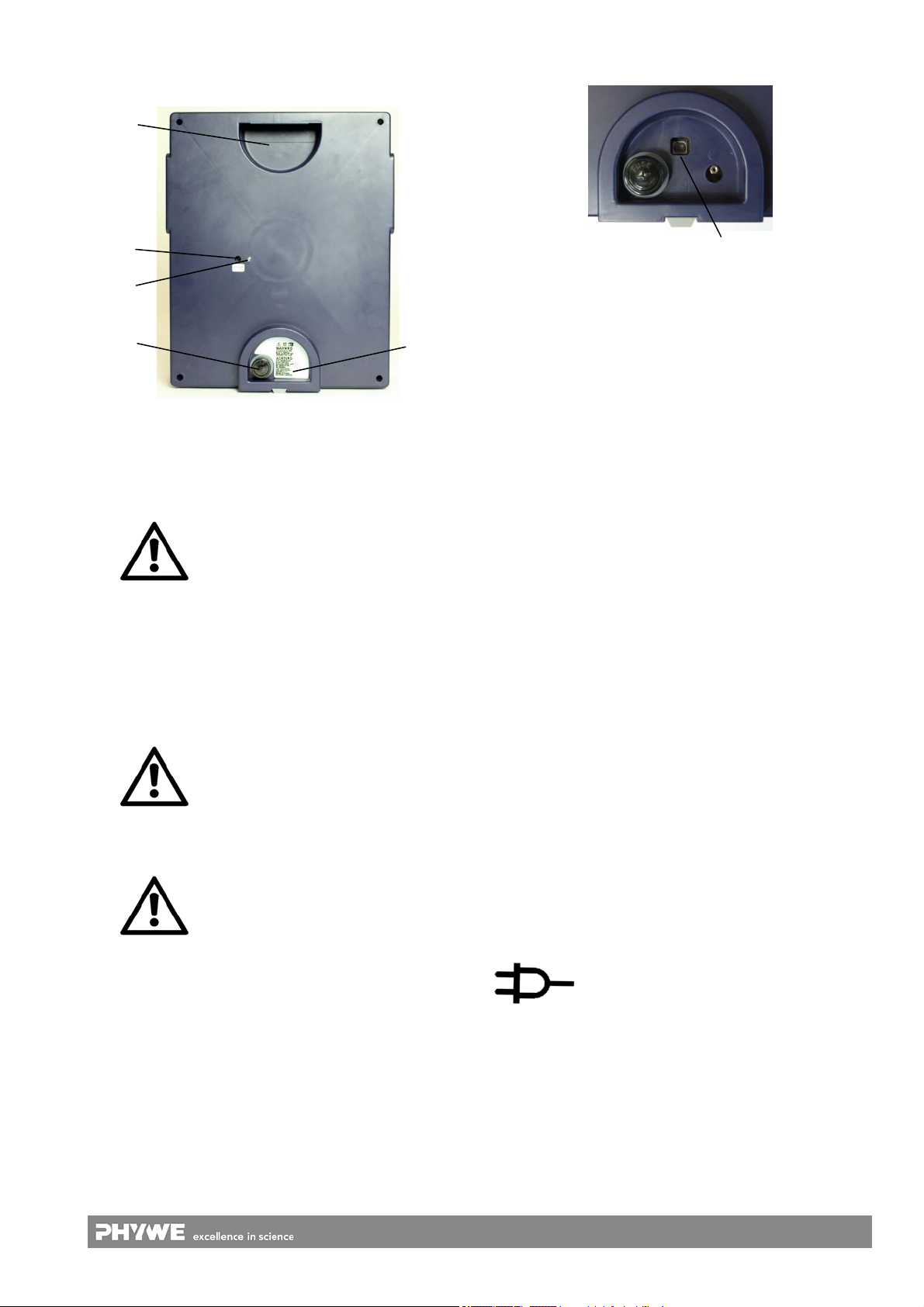
To switch the instrument on, select the desired type of cur-
rent with the aid of the operating mode selector (5). It will be
ready for operation after a turn-on period of several seconds.
The measuring range selector (4) and scale button (1) are
used to select the measurement unit and scale and, thereby,
the desired measuring range. After this step, the measuring
circuit can be connected.
5.2 Buzzer
The buzzer is used for signalling the following operating
states:
Short beep: Overrange, >5-10 % beyond the scale
range.
Display:
Elimination of the problem:
The overrange state must be eliminated by changing
the measuring range (scale) or by reducing the
measured variable!
Continuous sound: overrange and deactivation of the
measuring amplifier (to protect the device).
The pointer returns to “0”.
Display:
Elimination of the problem:
The overrange state must be eliminated by reducing
the measured variable!
After a waiting period of several minutes, the meas-
uring amplifier can be switched on again by chang-
ing the measuring range (selector 4) or operating
mode (selector 5).
5.3 Standby
To increase the service life of the battery, the instrument is
equipped with an automatic shut-off system that switches the
instrument off approx. 60 minutes after the last intervention
by an operator. The fact that the instrument has been
switched off is indicated by the inactive display and a flashing
"Power" LED (2).
In order to reactivate the instrument, the scale button (1), the
measuring range selector (4) or the operating mode selector
(5) must be actuated.
To switch the instrument completely off, the operating mode
selector must be set to "OFF".
5.4 Battery mode
The instrument can be operated with a connected charger or
by way of the integrated battery.
When there is only approx. 1 hour of battery life left, the fol-
lowing symbol will be displayed:
When the batteries are discharged, the instrument switches
itself off so that there will be no deep discharge and, thereby,
no damage to the batteries. After the automatic shut-off, the
instrument should be switched off with the aid of the operat-
ing mode selector (5) (OFF).
The instrument can be charged for as long as desired. Once
the battery is fully charged, the charge will be maintained.
5.5 Correct measurement of unsmoothed, pulsating DC
voltages and currents
When measuring pulsating DC voltages and currents like the
ones obtained from normal variable transformers with rectifi-
ers, moving coil instruments are subject to a fundamental er-
ror of measurement: These instruments indicate the mean
value instead of the root-mean-square (rms) value. In the
case of a pulsating DC voltage obtained by way of a bridge
rectifier, this mean value is almost exactly 11 % lower than
the rms value.
However, the instrument still enables the exact measurement
of the rms value of pulsating DC voltages and currents. Sim-
ply switch the instrument to the AC mode . In the case of
sinusoidal pulsating measurement signals, the instrument
indicates the exact rms value. The exact rms value is also
obtained in the case of distorted sinusoidal signals. (For pure
DC currents, the operating mode selector (5) should always
be set to since, otherwise, the measurement accuracy will
be reduced.)
5.6 Measurement of non-sinusoidal AC voltages and
currents
To measure AC voltages and currents, the voltages and cur-
rents are rectified in the ADM 3 light in the mode by way
of a true RMS-to-DC converter. The advantage of this
method is that, even in the case of signals that deviate sub-
stantially from the sinusoidal form, exact rms values will be
displayed. For signals with a crest factor (this is the ratio of
peak value to RMS value) of 4, hardly any influence of the
waveform on the measurement result can be observed.
5.7 Overload protection
The instrument is equipped with numerous protective devices
to protect it against damage caused nearly all conceivable
types of faults.
Voltage overload
The “V” socket (6) is protected against mains voltage in all of
the measuring ranges and protected by a surge protector
against higher voltages (short-time up to 1kV). For non-
hazardous voltages that are safe to touch, the protective
function is effective up to 10 kV.
A voltage is considered to be non-hazardous (i.e. safe to
touch) if it complies with the following conditions (according
to standard DIN EN 61010-1):
the values are smaller than 33 V
rms
in the case of AC
voltage or
smaller than 70 V in the case of DC voltage or
the current (terminated with 2 kΩ) is smaller than 2 mA in
the case of direct current or
the capacitive charge is smaller than 45 μC (valid up to
U<15 kV) or
the stored energy value is smaller than 350 mJ (valid for
U>15 kV).
Current overload
The socket „A“ (8) is protected against current overload by
two protective measures: An overload cut-off (thermal cut-off)
and a fuse for high currents. Due to overrange, the measur-
ing circuit “A” will be cut-off not later than 3 s and the measur-
ing circuit “mA” not later than 15 s. Depending on the over-
load of the current measuring ranges, a thermo switch may
temporarily disrupt the circuit.
After a cooling period of several minutes, the current meas-
urement function can be reactivated by selecting a new
measuring range (4) or a new operating mode (5). See also
section 5.2 “Buzzer”.