User Manual
D510T0001, valid for D-510
BSc, BRo, 2/26/2020
Physik Instrumente (PI) GmbH & Co. KG, Auf der Roemerstrasse 1, 76228 Karlsruhe, Germany Page 4 / 12
Phone +49 721 4846
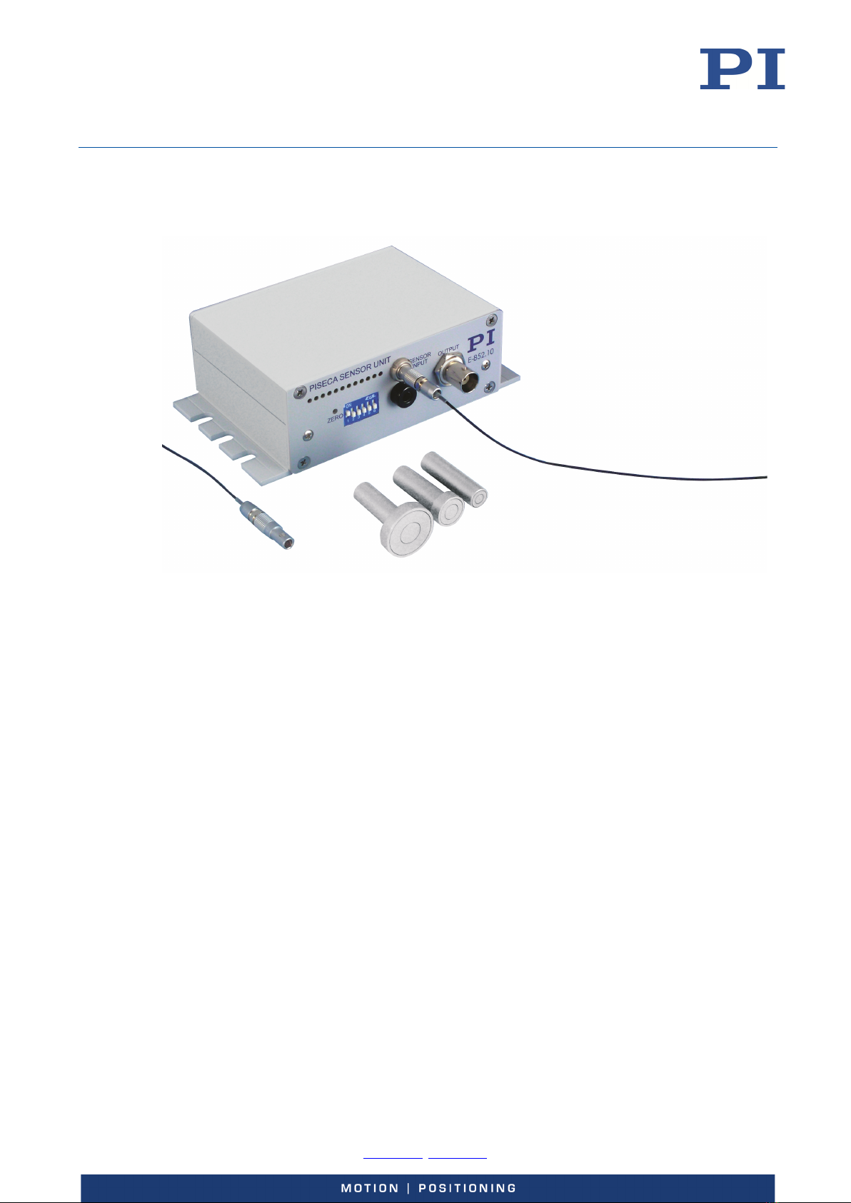
Product number Description
D-891.01E Sensor cable PISeca, 1 m
D-891.02E Sensor cable PISeca, 2 m
D-891.01A Sensor cable PISeca, right-angle connector, 1 m
D-891.02A Sensor cable PISeca, right-angle connector, 2 m
To order, contact our customer service department (p. 12).
General Considerations
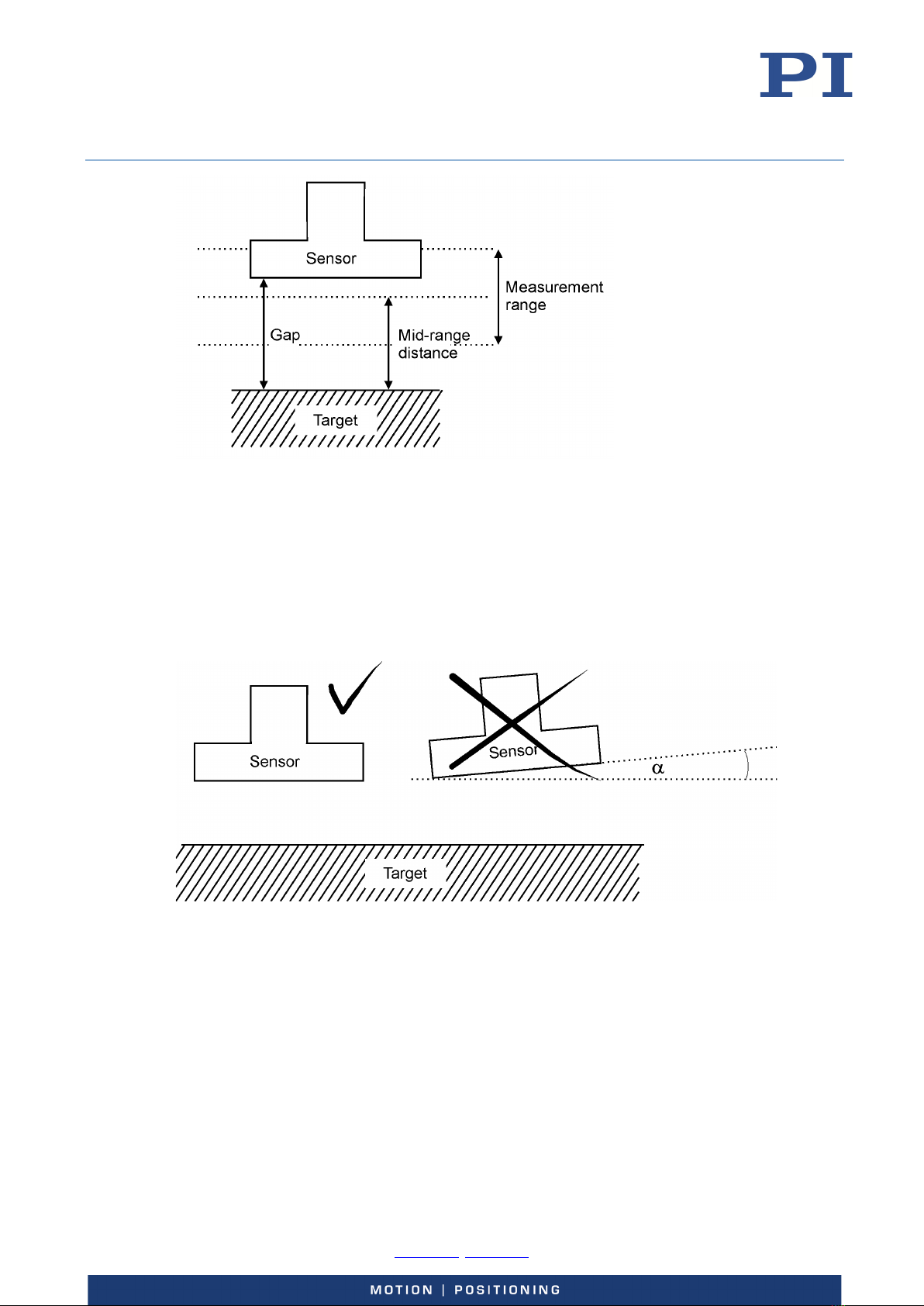
The performance of a capacitive sensor depends mainly on flatness of the target, mounting
parallelism and centricity.
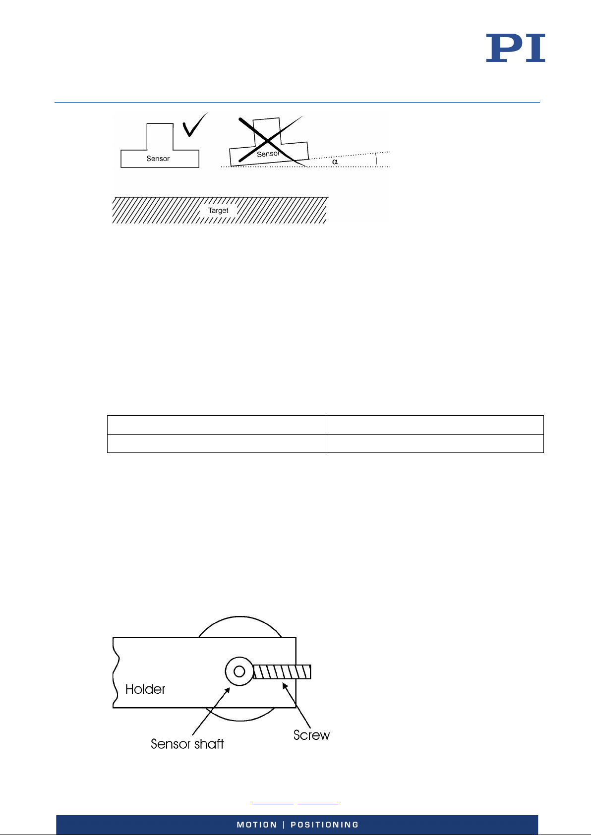
The sensor probe should be mounted with the utmost care in regard to parallelism and correct
mounting distance to achieve highest accuracy.
In regard to best linearity, a surface's roughness of better than N4 is suggested.
Please consider the following:
1. The PISeca system measures changes in capacitance between the sensor probe and a
conductive, grounded target surface. The target or structure under test should provide
a noise-free, low-impedance return path. To verify that a proper return path is present,
connect a ground lead directly from the target to the ground connector on the
electronics.
2. To minimize the capacitive influence of the connecting triaxial cable make the target
the moving part of the system.
3. Parallelism can influence the linearity and also the gain factor. The target ground plate
must be mounted parallel to the sensor surface.
4. The target area size should be considerably larger than the sensor area (by approx.
50%).
5. Measurement against a semi-conductor target connected to ground is also possible.
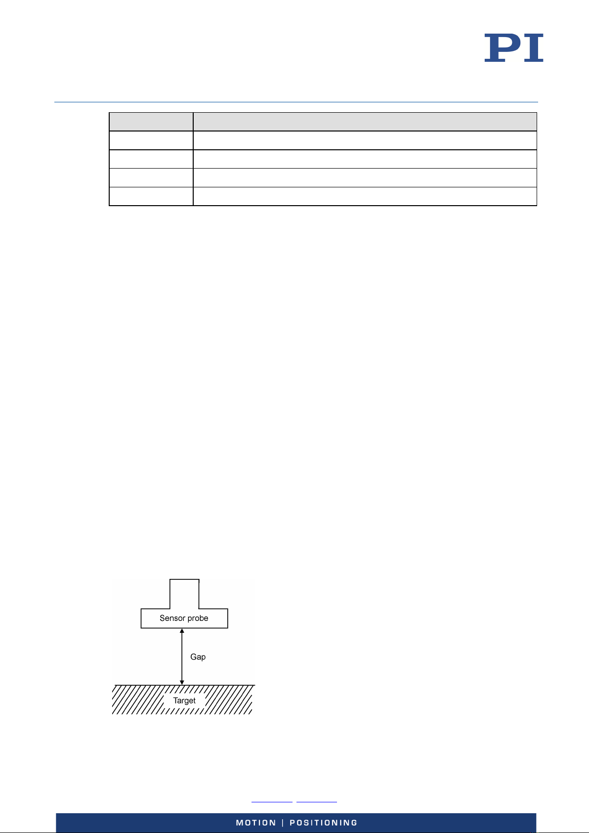
Figure 2: Definitions of "gap'" and "target"