PIAGGIO X8 250 i.e User manual

PIAGGIO WOULD LIKE TO THANK YOU
for choosing one of its products. We have prepared this manual to help you to get the very best from your vehicle. Please read it carefully before riding
the vehicle for the first time. It contains information, tips and precautions for using your vehicle. It also describes features, details and devices to assure
you that you have made the right choice. We believe that if you follow our suggestions, you will soon get to know your new scooter and it will serve you
well for a long time to come. This booklet forms an integral part of the vehicle; should the vehicle be sold, it must be transferred to the new owner.
X8 250 i.e.
Ed. 01_10/2012

The instructions given in this manual are intended to provide a clear, simple guide to using your vehicle; this booklet also details routine maintenance
procedures and regular checks that should be carried out on the vehicle at an authorised Dealer or Service Centre. The booklet also contains
instructions for simple repairs. Any operations not specifically described in this booklet require the use of special tools and/or particular technical
knowledge: to carry out these operations, refer to any authorised Dealer or Service Centres.
2

Personal safety
Failure to completely observe these instructions will result in serious risk of personal
injury.
Safeguarding the environment
Sections marked with this symbol indicate the correct use of the vehicle to prevent dam-
aging the environment.
Vehicle intactness
The incomplete or non-observance of these regulations leads to the risk of serious
damage to the vehicle and sometimes even the invalidity of the guarantee.
The signs that you see on this page are very important. They are used to highlight parts
of the booklet that should be read with particular care. The different symbols are used
to make each topic in the manual simple and quick to locate.
3

4

INDEX
VEHICLE...................................................................................... 7
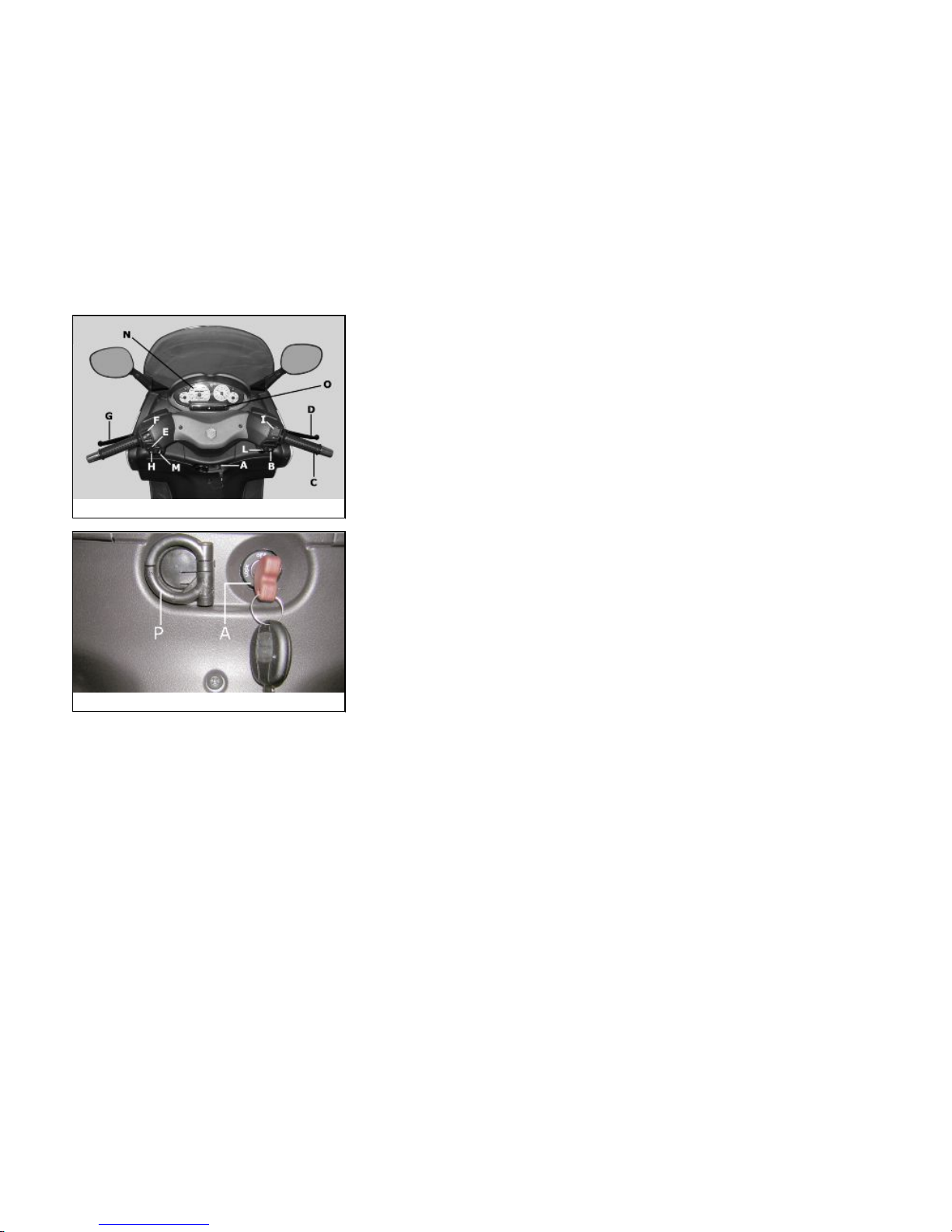
Dashboard................................................................................ 8
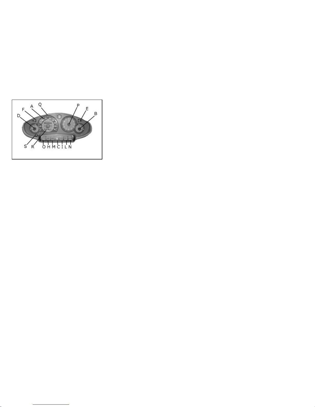
Analogueinstrumentpanel......................................................... 9
Clock......................................................................................... 10
Settingthehour/minutesfunction............................................. 10
Keyswitch.................................................................................. 10
Lockingthesteeringwheel....................................................... 11
Releasingthesteeringwheel................................................... 11
Switchdirectionindicators.......................................................... 11
Hornbutton................................................................................ 12
Lightswitch................................................................................ 12
Start-upbutton........................................................................... 13
Enginestopbutton...................................................................... 13
Theimmobilizersystem.............................................................. 13
Keys...................................................................................... 14
Immobilizerdeviceenabledindicatorled.................................. 15
Operation............................................................................... 15
Programmingtheimmobilizersystem...................................... 16
Saddleopeningremotecontrol.................................................... 18
Remotecontrolprogramming.................................................. 18
Powersupplysocket................................................................... 20
Thesaddle................................................................................. 20
Openingthesaddletoaccessthehelmetcompartmentbyremo-
tecontrol................................................................................. 21
Openingthesaddle................................................................. 22
Openingthesaddletoaccessthehelmetcompartmentinane-
mergency............................................................................... 23
Identification.............................................................................. 24
Reartopboxopeningbutton......................................................... 25
USE.............................................................................................. 27
Checks...................................................................................... 28
Refuelling.................................................................................. 28
Tyrepressure............................................................................. 30
Shockabsorbersadjustment...................................................... 31
Runningin.................................................................................. 32
Startinguptheengine.................................................................. 33
Precautions........................................................................... 34
Difficultstartup........................................................................... 35
Stoppingtheengine.................................................................... 35
Stand......................................................................................... 36
Automatictransmission.............................................................. 37
Safedriving................................................................................ 38
MAINTENANCE........................................................................... 41
Engineoillevel............................................................................ 42
Engineoillevelcheck............................................................... 42
Engineoiltop-up..................................................................... 42
Warninglight(insufficientoilpressure)..................................... 43
Engineoilchange.................................................................... 43
Huboillevel................................................................................ 45
Tyres......................................................................................... 47
Sparkplugdismantlement.......................................................... 48
Removingthesides.................................................................... 49
Removingtheairfilter.................................................................. 52
Airfiltercleaning......................................................................... 52
Coolingfluidlevel........................................................................ 53
Checkingthebrakeoillevel.......................................................... 55
Brakingsystemfluidtopup....................................................... 56
Battery....................................................................................... 57
Useofanewbattery................................................................. 57
Checkingtheelectrolytelevel................................................... 58
Long periods of inactivity.......................................................... 58
Fuses........................................................................................ 59
Frontlightgroup.......................................................................... 65
Headlightadjustment.............................................................. 66
Frontdirectionindicators............................................................. 66
Rearopticalunit.......................................................................... 67
5

Rearturnindicators..................................................................... 68
Numberplatelight....................................................................... 68
Helmetcompartmentlightingbulb............................................... 69
Rear-viewmirrors....................................................................... 69
Frontandreardiscbrake.............................................................. 69
Puncture.................................................................................... 70
delveicolo.................................................................................. 71
Cleaningthevehicle.................................................................... 72
TECHNICALDATA....................................................................... 77
Toolkit....................................................................................... 81
SPAREPARTSANDACCESSORIES........................................... 83
Warnings................................................................................... 84
SCHEDULEDMAINTENANCE..................................................... 87
Scheduledservicingtable........................................................... 88
6

X8 250 i.e.
Chap. 01
Vehicle
7

01_01
01_02
Dashboard (01_01, 01_02)
A= Ignition key-switch
B= Starter button
C= Throttle control
D= Front brake lever
E= Turn indicator switch
F= Headlight switch
G= Rear brake lever
H= Horn button
I= Engine cut-off switch
L= Boot opening switch
M= Saddle opening button
N= Instrument panel unit
O= Indicator unit
P= Bag hook
8
1 Vehicle

01_03
Analogueinstrumentpanel (01_03)
A = Twin scale speedometer (km/h and mph)
B = Fuel gauge
C = LED immobilizer / anti-theft device
D = Coolant temperature gauge
E = Right turn signal warning light
E = Left turn signal warning light
H = Low fuel warning light
I = Lights ON warning light
L = High-beam warning light
M = Low oil pressure warning light
N = Helmet compartment light ON warning light
O = Engine control telltale light and injection system failure warning light
P = Analogue clock
Q = Total odometer
R = Trip odometer
S = Trip odometer reset button
9
1 Vehicle

01_04
Clock (01_04)
The clock, powered directly by the vehicle's battery, may be set by pressing the «T»
button located inside the LHS glove-box on the knee-guard panel.
Pressingthebuttonforlessthanonesecondwilladdoneminutetothedisplayedtime;
Keep the «T» button pressed to rapidly increase the time.
Settingthehour/minutesfunction
Pressing the "RES" key increases the minutes of the indicated time one by one.
Hold the "RES" key down to increase the numbers faster.
01_05
Keyswitch (01_05)
LOCK = Ignition disabled, extractable key, mechanical antitheft device enabled.
OFF = Ignition disabled, extractable key,mechanical antitheft device disabled.
ON = Ready to start, non-extractable key, mechanical antitheft device disabled.
10
1 Vehicle

Lockingthesteeringwheel
Turn the handlebar to the left (as far as it will go), turn the key to «LOCK» and remove
the key.
Releasingthesteeringwheel
Reinsert the key and turn it to «OFF».
CAUTION
DO NOT TURN THE KEY TO «LOCK» OR «KEY OFF» WHILE RIDING.
01_06
Switchdirectionindicators (01_06)
Lever towards "S" = Left turn indicator is switched on;
Lever towards "D" = Right turn indicator is switched on;
The lever returns automatically to position "0" and the turn indicator "B" remains on;
press the lever to turn them off.
11
1 Vehicle

01_07
Hornbutton (01_07)
Push the «C» button to sound the horn.
01_08
Lightswitch (01_08)
0= Low-beam light
1 = High beam light
2 = Passing (flashing)
12
1 Vehicle

01_09
Start-upbutton (01_09)
To start the engine, press the starter button "G" while pulling either of the two brake
levers.
01_10
Enginestopbutton (01_10)
Functioning of the engine cut-off switch "I":
0= OFF
1= RUN
Theimmobilizersystem
In order to enhance theft protection, the vehicle is equipped with a «PIAGGIO IMMO-
BILIZER » electronic engine locking device that is activated automatically when the
ignition switch is removed. Upon start-up, the «PIAGGIO IMMOBILIZER» system
13
1 Vehicle

checks the starter key, and only if this key is recognised will the Immobiliser system
allow the vehicle to be started.
01_11
01_12
Keys (01_11, 01_12, 01_13)
Two types of keys are supplied together with the vehicle.
The red handgrip key «A» is the «MASTER» key.
Only a single copy of this key is supplied, which is necessary to program all your other
keys and for your dealer to perform some maintenance operations. For this reason it
is advised that it be used only in exceptional circumstances.
The black key "B" (single copy supplied) is used for normal operations such as:
- engine start up
- open the rear glove-box and the saddle (with remote control)
Together with the two keys, you will be given a CODE CARD bearing the same code
imprinted onto the two keys.
WARNING
LOOSING THE RED KEY PREVENTS ANY REPAIRS OF THE 'PIAGGIO IMMO-
BILIZER' SYSTEM AND THE ENGINE CONTROL UNIT.
WARNING
KEEPTHE'CODECARD' ANDTHE REDHANDGRIP KEYIN ASAFE PLACE(NOT
ON YOUR VEHICLE).
14
1 Vehicle

01_13
01_14
Immobilizerdeviceenabledindicatorled (01_14)
Activation of the "PIAGGIO IMMOBILIZER" system is signalled by a flashing "C" in-
dicator. In order to reduce battery discharge, the indicator LED turns off automatically
after 48 hours of uninterrupted functioning. Should the signal led system break down
in its flashing function, give information about the type of problem to an Authorised
Piaggio-Gilera Service Centre.
Operation
Every time the starter key is removed in the "OFF" or "LOCK" position, the safety
system activates the immobilizer system. Turning the key to "ON" disables the engine
lock, provided that the safety system recognises the code transmitted by the key. If
the code is not recognised, turn the key first to "OFF" and then to "ON"; if the lock
cannotbe disabled, try withthe other key supplied(red-coloured). If the enginecannot
be started, contact an Authorised Piaggio Service Centre, which is provided with
the electronic equipment required to detect and repair the system.
15
1 Vehicle

When additional keys are required, please note that data storage (up to 7 keys max.)
must be done on all keys, both new and existing ones.
Take the red handgrip key and all the black keys supplied to an Authorised Piaggio
Service Centre.
Thecodes of keys not submitted forthenew programming procedure are deleted from
the memory. Any lost keys will therefore not be enabled to start the engine.
WARNING
EACH KEY HAS ITS OWN AND UNIQUE CODE, WHICH MUST BE STORED IN
THE SYSTEM CONTROL UNIT MEMORY.
VIOLENT SHOCKS MAY AFFECT THE ELECTRONIC COMPONENTS OF THE
KEY.
IF OWNERSHIP OF THE VEHICLE IS TRANSFERRED TO ANOTHER PERSON,
THE KEY WITH THE RED GRIP (AS WELL AS THE OTHER KEYS) AND THE
"CODE CARD" MUST BE ALSO TRANSFERRED TO THE NEW OWNER.
Programmingtheimmobilizersystem
Below is described the procedure to follow for programming the PIAGGIO IMMOBIL-
ISER system and/or for storing other key codes. The programming procedure should
be carried out with the engine stop switch set to «RUN».
Procedurestart-redkey
Insert the red ignition key in the switch key (in "OFF" position) and turn it to "ON". After
1 - 3 seconds, turn the key to «OFF » again and pull it out.
16
1 Vehicle

Intermediatestep-blackkey
After pulling out the red key, insert the black key within 10 seconds and promptly turn
it to «ON». After 1-3 seconds, turn the key to «OFF» again and pull it out. In this way,
a maximum of 7 black keys can be programmed by repeating the above procedure
keeping the indicated times.
Finalstep-redkey
After pulling out the last blue key, insert the red key again and turn it to "ON" (this
operation should be performed within 10 seconds of pulling out the previous key).
Leave it in this position for 1 to 3 seconds and return it to the «OFF» position.
Properprogrammingcheck
Insert the red key disabling the transponder (i.e., tilt the key cap by 90°) and turn the
key to "ON". Perform the engine start-up operation. Ensure that the engine does not
start. Insert the black key and repeat the start-up operation. Check that engine starts.
WARNING
SHOULDTHE ENGINE STARTWITH THE REDKEY(WITH TRANSPONDEROFF),
OR IN THE EVENT OF WRONG OPERATION DURING PROGRAMMING, REPEAT
THE PROCEDURE FROM THE BEGINNING.
17
1 Vehicle

01_15
01_16
Saddleopeningremotecontrol (01_15, 01_16)
The scooter is fitted with a remote control to open the saddle. This remote control is
supplied together with the keys and it has been programmed to control the opening
device control unit at the manufacturing stage. If the remote control is lost, a new one
can be requested and programmed at any Authorised Piaggio Service Centre. The
remote control is powered by inner batteries that get discharged after extended used;
If the green LED turns on when the button is pressed, the remote control is working
properly.You may need toreplace the batteries if theremote control fails orif its range
of operation is reduced. To separate the two halves of the remote control, insert the
blade of a plain slot screwdriver at one point on the edge and slide it all around. When
the remote control is open, remove the two batteries from the contact terminal. Install
the two new CR1616 3V batteries with the positive pole facing the contact terminal.
Reassemble the remote control by pressing the two clip-on halves gently with your
fingers.
To open the saddle without using the remote control, follow the instructions in the
"Opening the saddle to reach the helmet compartment" or "Opening the saddle to
reach the helmet compartment in an emergency" sections.
Remotecontrolprogramming
Follow these steps to program the remote controls:
1. Insert the remote control key to be programmed in the steering lock key block.
2. Turn the key to «ON», press the button on the remote control, release the button,
then turn the key back to «OFF» within four seconds of turning «ON».
3. Wait 1 to 8 seconds.
4. Repeat steps 2 and 3 four more times without removing the key.
18
1 Vehicle

The control unit confirms the programming has been successful by opening the sad-
dle.
WARNING
TO STORE THE OTHER REMOTE CONTROLS TO MEMORY (8 MAXIMUM) YOU
NEED TO REPEAT THE WHOLE PROCEDURE AGAIN. FAILURE TO CARRY OUT
THESE OPERATIONS WITHIN THE INDICATED TIMES WILL RESULT IN THE
AUTOMATIC CANCELLATION OF THE PROCESS FOR PROGRAMMING THE
REMOTE-CONTROLLED KEYS.
WARNING
AVOIDPRESSINGTHEREMOTE CONTROL BUTTON MORE THAN ONCEWHEN
FAR AWAY FROM THE SCOOTER. THE SYNCHRONISM BETWEEN THE RE-
MOTE CONTROL AND THE RECEIVER CAN BE IMPAIRED. SHOULD THIS BE
THE CASE, REPEAT THE PROGRAMMING PROCEDURE. DO NOT KEEP THE
REMOTE CONTROL IN PLACES WITH TEMPERATURES EXCEEDING 60° C THE
BATTERY WILL RUN DOWN TOO QUICKLY.
WARNING
TO AVOID BATTERY DISCHARGE, THE SADDLE OPENING REMOTE CONTROL
RADIORECEIVER DEACTIVATES7 DAYSAFTER THELASTTIMETHEVEHICLE
WAS SHUT OFF.
JUST TURN THE KEY TO «ON» TO REACTIVATE THE RECEIVER.
19
1 Vehicle

01_17
Powersupplysocket (01_17)
The scooter is equipped with a 12V socket, "D", inside the LHS glove compartment.
This may be used to power electrical devices with a maximum power below 180W (i.e.
mobile phones, flashlights, etc.).
CAUTION
PROLONGED USE OF THE PLUG SOCKET MAY RESULT IN PARTIAL DIS-
CHARGE OF THE BATTERY
01_18
Thesaddle (01_18, 01_19, 01_20)
The saddle is supplied with a protection cover which may be used in case of rain.
Lift the saddle and extract the cover from its housing, then extend it over the whole
length of the saddle, starting from the front-end; do not over stretch the cover to avoid
tearing the material; close the saddle.
CAUTION
DON'T RIDE THE VEHICLE WITH THE PROTECTION COVER ON THE SADDLE .
20
1 Vehicle
Table of contents
Other PIAGGIO Bicycle manuals