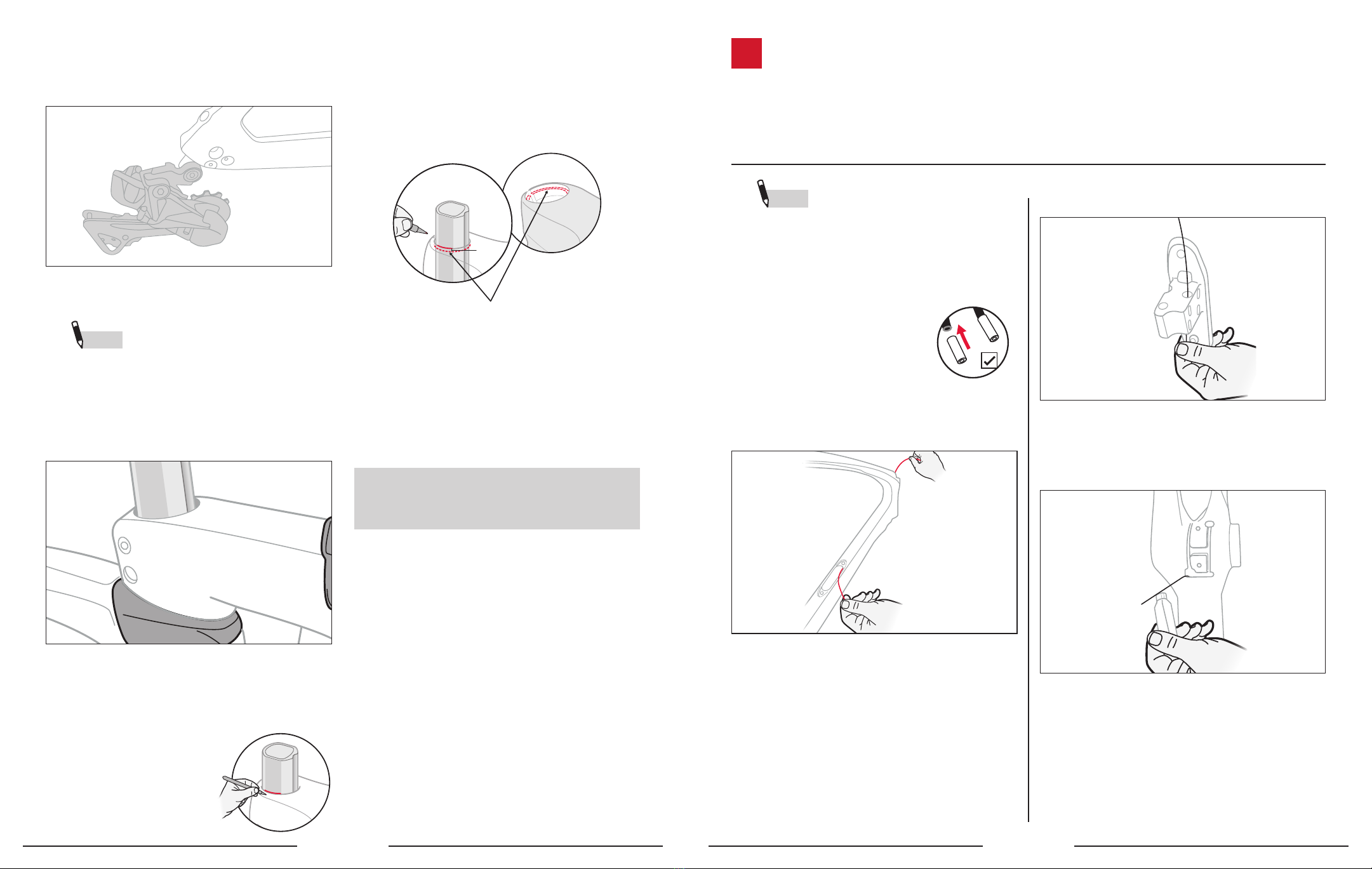
5. Install the rear derailleur on the the rear derailleur
hanger. Tighten to the OEM torque spec.
CUT THE FORK STEERER TUBE:
NOTE You will need to temporarily install the fork,
headset and stem together to get the correct location
for cutting the steerer tube.
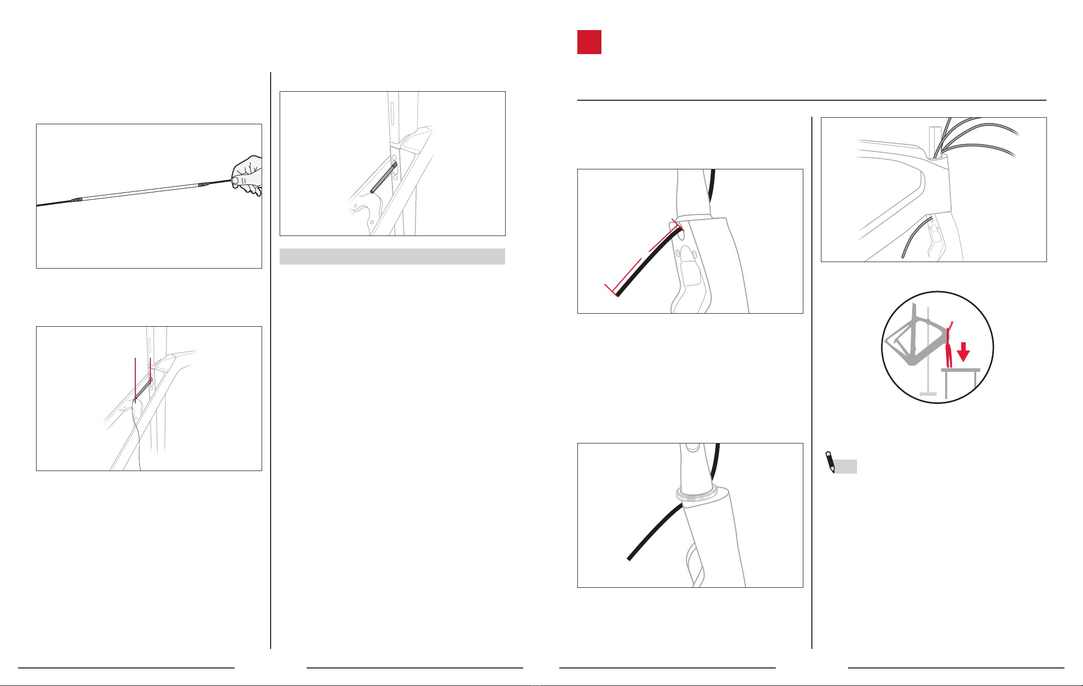
1. Holding the fork legs, slide the stem down the steerer
tube until it is firmly seated on top of the bearing top
cap or shaped spacers. Lightly tighten the stem
pinch bolts.
2. Determine the preferred cut length. Use additional
spacers above the stem until you are certain about the
desired stack height (handlebar height).
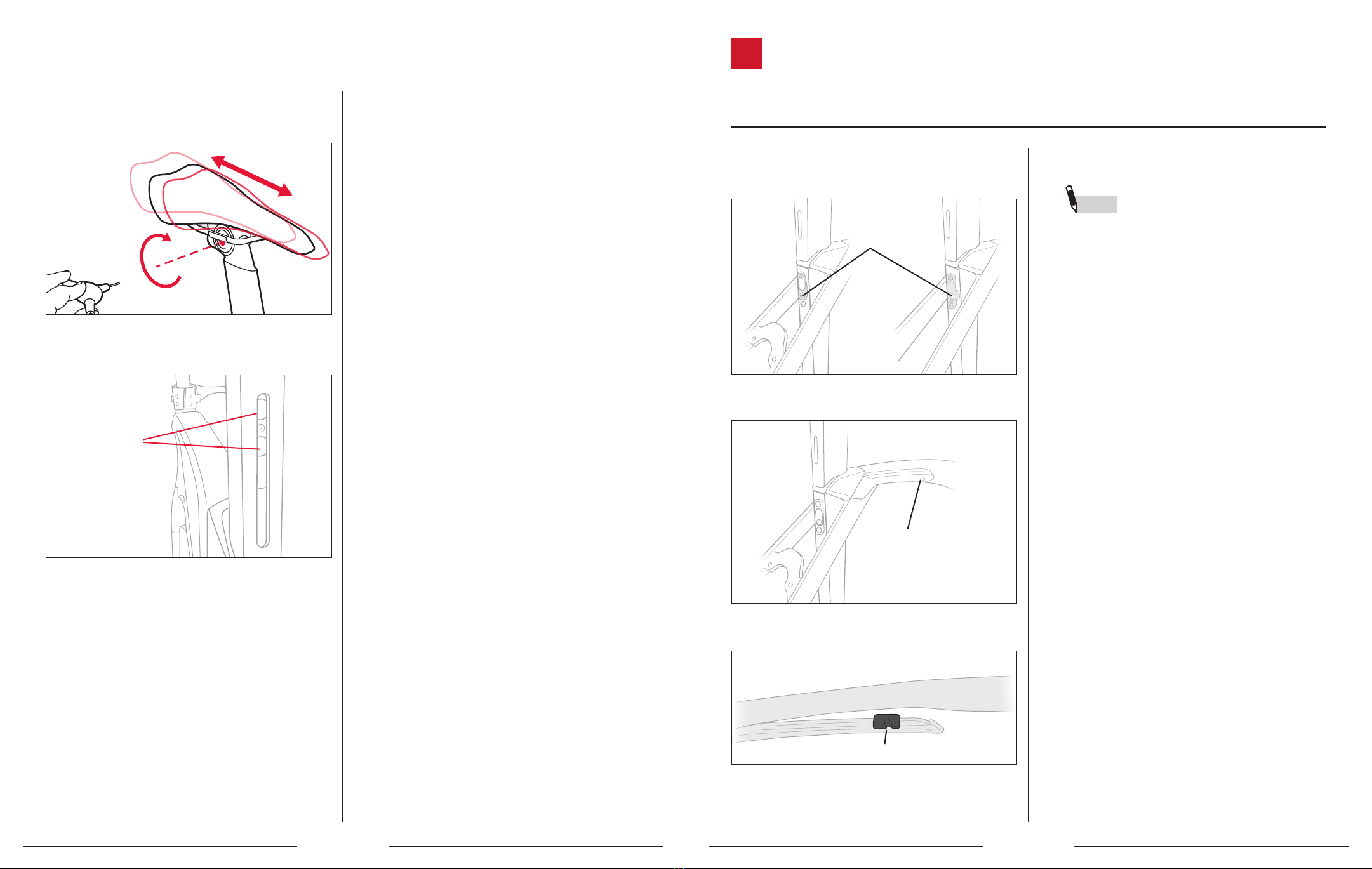
3. Mark a fine line on the flat side of the steerer tube
along the top edge of the
stem.
4. If you are planning to use the 5 mm spacer recessed
in the stem, your actual cutting line should be 5 mm
below the pencil mark made in the prior step. If you
are planning on using a 5 mm headset spacer above
the stem, cut on the line.
5 mm
5. IMPORTANT: There is a 5 mm spacer built into the
stem which allows you to install the stem top cap flush
with the stem.
6. Disassemble the stem and headset from the steerer
tube.
7. Proceed with cutting the steerer at the selected
location from Steps 3/4 using a standard carbon
steerer cutting process.
If you’re building a mechanical drivetrain, go to Step 2.
Install the Mechanical Control Centre on page 5.
If you’re building a Di2 drivetrain, go to Step 3. Install
the Di2 Cables and Housings on page 9.
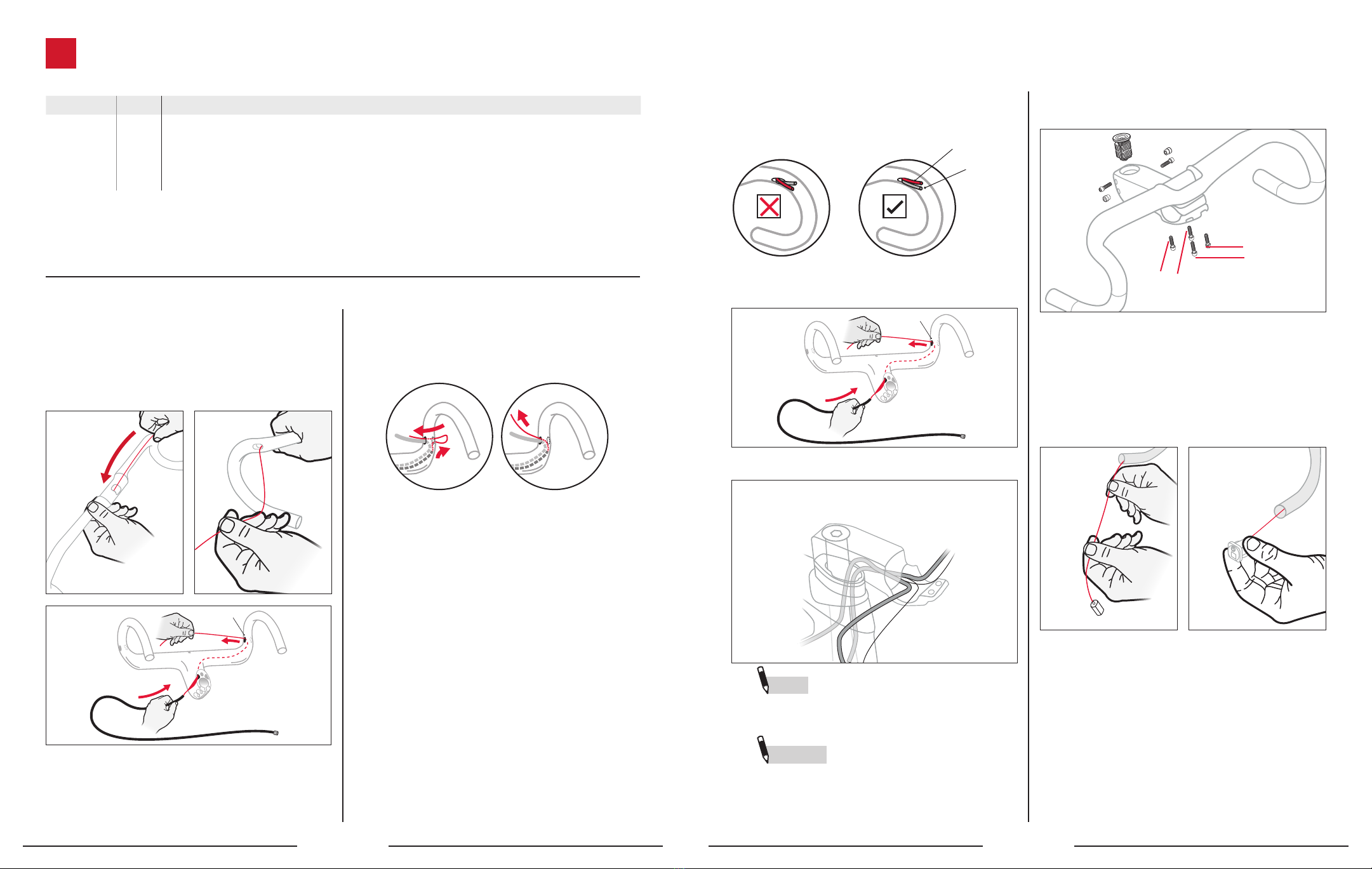
NOTE There is plastic tubing inside the frame
to help with initial cable and wire routing. It is not
intended to be left in the frame.
1. Refer to the table at the front of this manual to cut
the front and rear derailleur cable housings to the
appropriate lengths.
2. Attach ferrules to both ends of
the derailleur housings. Route the
cables into their housings.
3. Mark the FD housing with tape to
identify it.
4. Route the FD cable/housing from the head tube to the
cutout in the downtube.
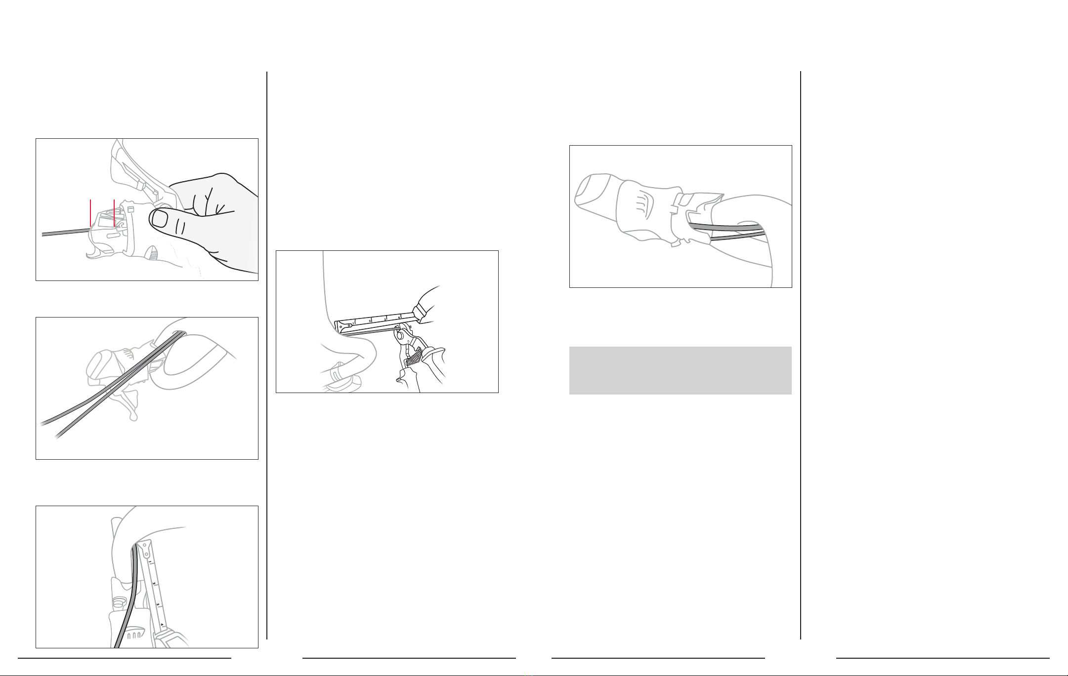
5. Pass the FD cable through the top hole of the
control centre.
6. Set the control centre loosely in the downtube cutout.
7. Route the FD cable down the downtube and push it
through the bottom bracket guide slot.
2INSTALL THE MECHANICAL CONTROL CENTRE
TOOLS AND MATERIALS REQUIRED
• Park Tool Routing Kit • Marker • Ferrules
• Mechanical control centre • Rear derailleur cable stop • Rear derailleur cable liner
• Cable cutter • Bottom bracket guide • Ruler
4 5


 owner's manual")


