3
How to use the Manual
Remark
RemarkRemark
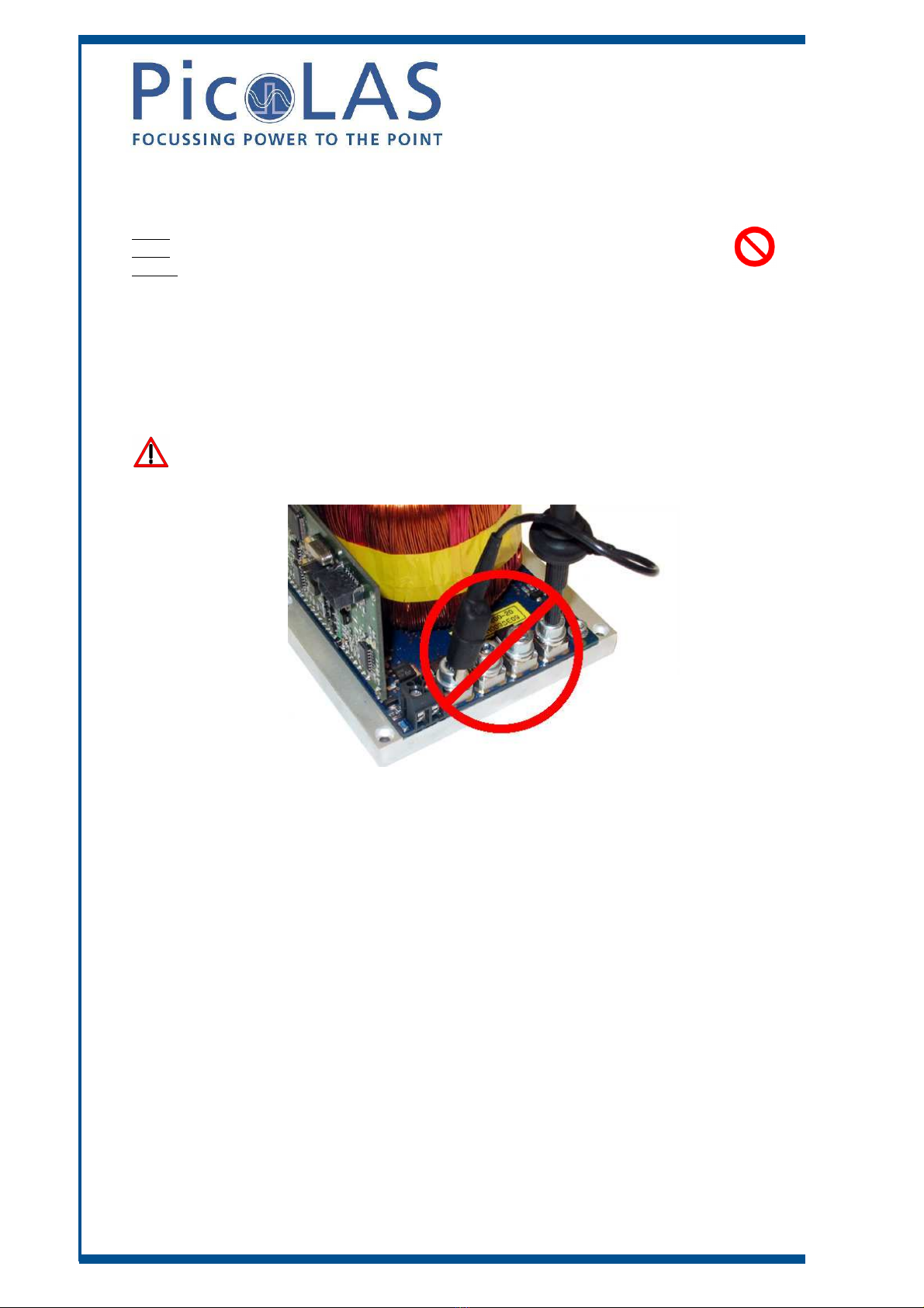
Remark: The LDP
: The LDP: The LDP
: The LDP-
--
-QCW described in this manual is a base
QCW described in this manual is a baseQCW described in this manual is a base
QCW described in this manual is a base-
--
-plate cooled laser diode
plate cooled laser diode plate cooled laser diode
plate cooled laser diode
driver. Improper cooling may cause an internal over temperature shu
driver. Improper cooling may cause an internal over temperature shudriver. Improper cooling may cause an internal over temperature shu
driver. Improper cooling may cause an internal over temperature shutdown. The two
tdown. The two tdown. The two
tdown. The two
fans in one side of the unit have to prevent local thermal hot spots inside the unit. They
fans in one side of the unit have to prevent local thermal hot spots inside the unit. They fans in one side of the unit have to prevent local thermal hot spots inside the unit. They
fans in one side of the unit have to prevent local thermal hot spots inside the unit. They
can not compensate improper base plate cooling. The air inside an enclosure within an
can not compensate improper base plate cooling. The air inside an enclosure within an can not compensate improper base plate cooling. The air inside an enclosure within an
can not compensate improper base plate cooling. The air inside an enclosure within an
OEM application is usually enough to yield enough air flow. Plea
OEM application is usually enough to yield enough air flow. PleaOEM application is usually enough to yield enough air flow. Plea
OEM application is usually enough to yield enough air flow. Please
se se
se do not cover any
do not cover any do not cover any
do not cover any
ventilation slots.
ventilation slots.ventilation slots.
ventilation slots.
Base plate cooling
Base plate coolingBase plate cooling
Base plate cooling: Depending on the final application and operation regime, this unit
: Depending on the final application and operation regime, this unit : Depending on the final application and operation regime, this unit
: Depending on the final application and operation regime, this unit
may stay none
may stay nonemay stay none
may stay none-
--
-cooled or must be assembled onto a heat sink.
cooled or must be assembled onto a heat sink. cooled or must be assembled onto a heat sink.
cooled or must be assembled onto a heat sink.
Please refer to chapter Power dissipation for more details about the
Please refer to chapter Power dissipation for more details about the Please refer to chapter Power dissipation for more details about the
Please refer to chapter Power dissipation for more details about the thermal power
thermal power thermal power
thermal power
losses during operation.
losses during operation.losses during operation.
losses during operation.
You me use a passively or an actively air/water cooled device.
You me use a passively or an actively air/water cooled device. You me use a passively or an actively air/water cooled device.
You me use a passively or an actively air/water cooled device.
Housing: All units are delivered with housing. Changes are possible; the units can be
Housing: All units are delivered with housing. Changes are possible; the units can be Housing: All units are delivered with housing. Changes are possible; the units can be
Housing: All units are delivered with housing. Changes are possible; the units can be
delivered without housing upon request.
delivered without housing upon request. delivered without housing upon request.
delivered without housing upon request.
Before powering on your u
Before powering on your uBefore powering on your u
Before powering on your unit, read this manual thoroughly and make sure your
nit, read this manual thoroughly and make sure your nit, read this manual thoroughly and make sure your
nit, read this manual thoroughly and make sure your
understood it fully.
understood it fully. understood it fully.
understood it fully.
Please pay attention to all safety warnings.
Please pay attention to all safety warnings.Please pay attention to all safety warnings.
Please pay attention to all safety warnings.
If you have any doubt or suggestion, please do not hesitate to contact us!
If you have any doubt or suggestion, please do not hesitate to contact us!If you have any doubt or suggestion, please do not hesitate to contact us!
If you have any doubt or suggestion, please do not hesitate to contact us!