FLETCHER Alfamacchine U500 User manual

EN INSTRUCTIONS MANUAL
PLEASE RETAIN FOR FUTURE REFERENCE
Name
Function
Model / Type
Serial number
Year of manufacture
Manual Revision
FRAME ASSEMBLING MACHINE
ASSEMBLY OF FRAMES BY INSERTION OF METAL V-NAILS
U500-U600 (previous version MP - MC)
02

TRANSLATION OF THE ORIGINAL INSTRUCTIONS (Keep for future reference)
Codice Documento Rev. Data di salvataggio Data di stampa
U500 - U600 ISTRUZIONI 02 04/11/2015 04/11/2015
EN
2
Alfamacchine S.r.l.
Via Selva 23/25
47122 Forlì - Italy
DICHIARAZIONE DI CONFORMITA’ CE
CE CONFORMITY DECLARATION
Il Fabbricante / the Manufacturer Alfamacchine S.r.l.
con sede legale in / Address Via Selva, 23/25 47122 Forlì - Italy
DICHIARA, / Hereby DECLARES,
sotto la propria responsabilità, under its sole responsibility,
che la macchina: that the machine:
Denominazione / Product Name : FRAME ASSEMBLING MACHINE
Funzione / Purpose : ASSEMBLY OF WOODEN AND SYNTHETIC MDF MOULDINGS USING METAL
V-NAILS
Modello/ Model Name : U500
Tipo / Type : ELECTRO-PNEUMATIC
Numero di Serie / Serial Number :
E’ CONFORME ALLE DISPOSIZIONI PREVISTE DALLE DIRETTIVE:
COMPLIES WITH THE BELOW MENTIONED STANDARDS AND DIRECTIVES:
- 2006/42/CE, Direttiva Macchine / Machinery Directive
- 2004/108/CE, Direttiva EU600 / EU600 Directive
poiché rispetta tutti i requisiti essenziali di sicurezza e sanitari che le concernono.
because it complies with all the essential safety health which affect
Fascicolo Tecnico costituito presso : ALFAMACCHINE S.R.L.
Technical File drawn up by: ALFAMACCHINE S.R.L.
Forlì ,
___________________________________
Data / Issued Date : Firma il Legale rappresentante / Signature of representative

TRANSLATION OF THE ORIGINAL INSTRUCTIONS (Keep for future reference)
Codice Documento Rev. Data di salvataggio Data di stampa
U500-U600 ISTRUZIONI 02 04/11/2015 04/11/2015 EN
3
Alfamacchine S.r.l.
Via Selva 23/25
47122 Forlì - Italy
CE DECLARATION OF CONFORMITY
CE CONFORMITY DECLARATION
Il Fabbricante / the Manufacturer Alfamacchine S.r.l.
con sede legale in / Address Via Selva, 23/25 47122 Forlì - Italy
DICHIARA, / Hereby DECLARES,
sotto la propria responsabilità, under its sole responsibility,
che la macchina: that the machine:
Denominazione / Product Name : FRAME ASSEMBLING MACHINE
Funzione / Purpose : ASSEMBLY OF WOODEN AND SYNTHETIC MDF MOULDINGS USING METAL
V-NAILS
Modello/ Model Name : U600
Tipo / Type : ELECTRO-PNEUMATIC
Numero di Serie / Serial Number :
E’ CONFORME ALLE DISPOSIZIONI PREVISTE DALLE DIRETTIVE:
COMPLIES WITH THE BELOW MENTIONED STANDARDS AND DIRECTIVES:
- 2006/42/CE, Direttiva Macchine / Machinery Directive
- 2004/108/CE, Direttiva EU600 / EU600 Directive
poiché rispetta tutti i requisiti essenziali di sicurezza e sanitari che le concernono.
because it complies with all the essential safety health which affect
Fascicolo Tecnico costituito presso : ALFAMACCHINE S.R.L.
Technical File drawn up by: ALFAMACCHINE S.R.L.
Forlì ,
___________________________________
Data / Issued Date : Firma il Legale rappresentante / Signature of representative

TRANSLATION OF THE ORIGINAL INSTRUCTIONS (Keep for future reference)
Codice Documento Rev. Data di salvataggio Data di stampa
U500 - U600 ISTRUZIONI 02 04/11/2015 04/11/2015
EN
4

TRANSLATION OF THE ORIGINAL INSTRUCTIONS (Keep for future reference)
Codice Documento Rev. Data di salvataggio Data di stampa
U500-U600 ISTRUZIONI 02 04/11/2015 04/11/2015 EN
1
TRANSLATION OF THE ORIGINAL INSTRUCTIONS
INDEX
EN
1. INTRODUCTION TO USE ......................................................................................................................................................... 2
1.1. HOW TO CONSULT THIS MANUAL AND THE SYMBOLS ADOPTED ....................................................................... 2
.................................................................................................... 2
1.3. TYPE OF USE AND CONTRAINDICATIONS............................................................................................................... 3
1.4. TECHNICAL FEATURES.............................................................................................................................................. 5
1.5. PRODUCTS PROCESSED - HANDLED OR GENERATED ........................................................................................ 6
1.6. EMISSION OF AIRBORNE NOISE............................................................................................................................... 6
1.7. RESIDUAL RISKS - GENERAL INFORMATION .......................................................................................................... 7
1.8. RESIDUAL RISKS ........................................................................................................................................................ 7
1.9. INFORMATION ON EMC.............................................................................................................................................. 8
1.10. DESCRIPTION OF SAFETY FUNCTIONS................................................................................................................... 8
1.11. DESCRIPTION OF THE MACHINE............................................................................................................................ 10
1.12. MAIN MACHINE COMPONENTS................................................................................................................................ 10
2. INSTALLATION ....................................................................................................................................................................... 14
2.1. STORAGE................................................................................................................................................................... 14
2.2. CHECKS ON RECEPTION......................................................................................................................................... 15
2.3. TRANSPORT, LIFTING AND HANDLING................................................................................................................... 15
2.4. LIFTING AND HANDLING .......................................................................................................................................... 16
2.5. REMOVING THE PACKAGING .................................................................................................................................. 17
3. PRELIMINARY PREPARATION AND ADJUSTMENT PROCEDURES ................................................................................. 18
3.1. POSITIONING............................................................................................................................................................. 18
3.2. LEVELLING THE MACHINE....................................................................................................................................... 18
3.3. ASSEMBLY OF SEPARATELY SHIPPED UNITS ...................................................................................................... 19
3.4. POWER SUPPLIES.................................................................................................................................................... 21
4. INITIAL START-UP AND USE OF THE MACHINE................................................................................................................. 24
4.1. WORKSTATIONS AND OPERATORS’ TASKS........................................................................................................... 25
4.2. DESCRIPTION OF ACTUATORS, SIGNALS AND ALARMS ..................................................................................... 27
4.2.1. COMMAND AND SIGNALLING ACTUATORS ........................................................................................................... 27
4.2.2. START-UP FUNCTIONS............................................................................................................................................. 28
4.2.3. STOP FUNCTIONS (TIMED AND SAFETY STOPS) ................................................................................................. 28
4.3. CHECKS, ADJUSTMENTS AND START-UP ............................................................................................................. 29
4.4. START-UP................................................................................................................................................................... 29
4.4.1. CHECKS ON CYCLE START-UP AND PERIODICAL INSPECTIONS....................................................................... 29
4.4.2. PRODUCTION / PROGRAMMING PARAMETERS SETUP ...................................................................................... 32
4.4.3. MECHANICAL ADJUSTMENTS / MAINTENANCE ................................................................................................... 39
4.4.4. RESERVED PAGES ................................................................................................................................................... 51
4.5. WORKING CYCLE...................................................................................................................................................... 56
4.5.1. CYCLE STOP ............................................................................................................................................................. 57
4.5.2. SWITCH-OFF.............................................................................................................................................................. 57
5. MAINTENANCE, TROUBLESHOOTING, AND CLEANING .................................................................................................. 58
5.1. MAINTENANCE TECHNICIAN REQUIREMENTS ..................................................................................................... 58
5.2. WORK STATIONS AND MAINTENANCE TECHNICIAN DUTIES.............................................................................. 58
5.3. MAINTENANCE PRESCRIPTIONS............................................................................................................................ 59
5.4. GENERAL WARNINGS .............................................................................................................................................. 59
5.5. ISOLATION FROM EXTERNAL ENERGY SOURCES............................................................................................... 60
5.6. ROUTINE MAINTENANCE......................................................................................................................................... 60
5.7. TASKS THAT CAN BE PERFORMED BY THE OPERATOR ..................................................................................... 61
5.8. TASKS THAT CAN BE PERFORMED ONLY BY MAINTENANCE TECHNICIANS ................................................... 62
5.9. CLEANING.................................................................................................................................................................. 64
5.9.1 CLEANING THE TOUCHSCREEN............................................................................................................................. 65
5.9.2 REPLACING THE PROTECTIVE FILM ON THE DISPLAY........................................................................................ 65
5.10. LUBRICATION ............................................................................................................................................................ 66
6. TROUBLESHOOTING AND RELEASE OF MOVING PARTS ............................................................................................... 68
7. REINSTALLATION AND REUSE ............................................................................................................................................ 70
8. EXTINGUISHING MEDIA........................................................................................................................................................ 70
9. SCRAPPING AND DISPOSAL. .............................................................................................................................................. 70
9.1. SCRAPPING............................................................................................................................................................... 70
9.2. DISPOSAL .................................................................................................................................................................. 71
PNEUMATIC DIAGRAM U500.......................................................................................................................................................... 72
PNEUMATIC DIAGRAM U600 ......................................................................................................................................................... 73
CAPS PNEUMATIC DIAGRAM ........................................................................................................................................................ 74
WIRING DIAGRAM U500 ................................................................................................................................................................. 75
WIRING DIAGRAM U600 ................................................................................................................................................................. 76
CAPS WIRING DIAGRAM ............................................................................................................................................................... 77
EXPLODED-VIEW DRAWINGS U600-U500 .................................................................................................................................... 78

TRANSLATION OF THE ORIGINAL INSTRUCTIONS (Keep for future reference)
Codice Documento Rev. Data di salvataggio Data di stampa
U500 - U600 ISTRUZIONI 02 04/11/2015 04/11/2015
EN
2
DANGER - WARNING
BEFORE USING THE MACHINE PLEASE READ THIS MANUAL CAREFULLY SO THAT YOU BECOME FAMILIAR WITH THE
MACHINE, ITS ENVISAGED USE AND ANY RISKS ASSOCIATED WITH IT.
Keep the Use and Maintenance Manual in good condition: Remember, it is an integral part of the machine. Always refer to the manual
to get best machine performance in maximum safety while performing the operations described therein.
This manual must be kept in an easily accessible place, near the machine, at all times so that it can be consulted whenever necessary.
DANGER - WARNING
USE THE MACHINE SOLELY AND EXCLUSIVELY FOR THE USES INDICATED AND IN ACCORDANCE WITH THE
RECOMMENDATIONS PROVIDED IN THIS MANUAL. NEVER TAMPER WITH IT, FORCE IT OR USE IT IN ANY INAPPROPRIATE
MANNER.
1. INTRODUCTION TO USE
1.1. HOW TO CONSULT THIS MANUAL AND THE SYMBOLS ADOPTED
Please pay particular attention to the words “DANGER – WARNING”, “DANGER – CAUTION” and “NOTES” as used in this manual.
To draw the user’s attention to certain information and provide warning messages, the operations described in this manual are accompanied
by symbols and notes to highlight the presence of any hazards and indicate the safe use of the equipment. These symbols and notes
belong to various categories as indicated below:
DANGER – WARNING: IMPORTANT INFORMATION CONCERNING GENERAL SAFETY.
DANGER-CAUTION: highlights situations where careful and sensible actions are essential.
NOTES: information of a technical nature.
Safety warning on machine use
Part of the equipment remains live even
when the door is open and with the electrical
power switch turned on.
To turn off the power supply act on the upline
cut-off device on the power supply.
EC dataplate
230V - 50-60Hz
Etichetta Descrizione
Wear protective googles.
Wear protective gloves.
Wear safety footwear
Wear ear defenders.
the corners of the guards.

TRANSLATION OF THE ORIGINAL INSTRUCTIONS (Keep for future reference)
Codice Documento Rev. Data di salvataggio Data di stampa
U500-U600 ISTRUZIONI 02 04/11/2015 04/11/2015 EN
3
Sticker Description
DISCONNECT ONLY WHEN THE MACHINE IS STOPPED
LIVE EQUIPMENT EVEN WHEN THE DOOR IS OPEN.
TO CUT OFF THE POWER SUPPLY ACT ON THE MAIN
ELECTRICAL ENCLOSURE POWER SWITCH
DISCONNECT THE POWER SUPPLY BEFORE OPENING
THE ELECTRICAL ENCLOSURE
Access to the powered electrical enclosure is permitted
who must use a special key or tool to open it. It is prohibited
to carry out work on live equipment. Any exceptions to this
prohibition must be authorized by the person in charge
and are subject to the adoption of all envisaged safety
regulations.
Indicates the method for disconnecting the plug from the power
socket.
Indicates how to disconnect the power supply.
Indicates how to access the electrical enclosure.
1.3. TYPE OF USE AND CONTRAINDICATIONS.
PERMITTED USE
The machine described herein is designed to be run by 1 operator
suitably trained and instructed with regard to residual risks. The
operator must have the same skills, in terms of safety, as the
maintenance technicians and adequate professional competence.
During its PERMITTED AND REASONABLY PREDICTABLE USE,
the machine may be used exclusively:
for pictures, mirrors, display cases, cupboard doors etc.) in
accordance with the characteristics described in the heading
“Products Processed - Handled or Generated”. Use of the
machine to perform processes other than those described in
this manual is to be considered improper and therefore strictly
prohibited.
the dimensions specified in the heading “TECHNICAL
CHARACTERISTICS”.
It is also compulsory:
received adequate training/information concerning machine
operations, performance and any hazards associated with its
use.
operating area before proceeding with any operations
whatsoever.
starting to work with the machine.
where it is to be used, that it is installed on a level, smooth and
load bearing capacity to support the weight of the machine.
of ambient lighting and ensure there are no areas of shadow,
glare, or potentially hazardous strobe effects.
stop buttons on the electrical panel.
electrical and compressed air supplies, to safely discharge any
residual energy in the machine circuits, and wait for all parts at
high temperatures to cool down adequately.

TRANSLATION OF THE ORIGINAL INSTRUCTIONS (Keep for future reference)
Codice Documento Rev. Data di salvataggio Data di stampa
U500 - U600 ISTRUZIONI 02 04/11/2015 04/11/2015
EN
4
UNINTENDED USE
DANGER - WARNING
THE MACHINE MUST NOT BE USED IN A PROHIBITED MANNER. SPECIFICALLY:
or materials with different characteristics to those previously described in the heading “TECHNICAL CHARACTERISTICS”.
all liability.
FORBIDDEN USE
DANGER - WARNING
FURTHERMORE IT IS PROHIBITED TO USE THE MACHINE IN AN INCORRECT MANNER, IN PARTICULAR:
authorized to do so,
protective device (mechanical or electrical) deactivated and/or non-functional,
in this instruction manual,
beforehand,
elements have come to a complete standstill.
as indicated in this manual,
- outdoors or worksites with open windows and doors,
- processing of materials and products that are not expressly indicated in the present manual,
- processing of metal materials made of aluminium, lightweight alloys, and steel and its alloys.
DANGER – CAUTION
The manufacturer cannot be held liable for any faults caused by unreasonable, improper and/or incorrect use of the
machine.
always consult the manufacturer’s engineering department.
The user is always responsible for providing suitable personal protective equipment to machine operators and for informing them on the
permissible uses of the machine.
PERSONNEL AUTHORIZED TO USE THE MACHINE
accordance with the characteristics described below:

TRANSLATION OF THE ORIGINAL INSTRUCTIONS (Keep for future reference)
Codice Documento Rev. Data di salvataggio Data di stampa
U500-U600 ISTRUZIONI 02 04/11/2015 04/11/2015 EN
5
Operators / Apprentices:
PERMITTED AMBIENT CONDITIONS AND OPERATING LIMITS
DANGER - WARNING
THIS MACHINE IS NOT SUITABLE FOR USE IN POTENTIALLY EXPLOSIVE ATMOSPHERES.
INSTALLATION AND USE IS SUCH AN ATMOSPHERE IS THEREFORE PROHIBITED.
manual.
1.4. TECHNICAL FEATURES
U600 Machine characteristics
Dimensions of the working bench (WxL)..............................................................................................................350X680mm - 14”x26”3/4
Max. machine length............................................................................................................................................................ 730mm - 28”3/4
Machine width ...................................................................................................................................................................... 800mm - 34”3/4
................................................................................................................. 980mm - 38”1/2
....................................................................................................................... 1310mm - 52”
Weight ................................................................................................................................................................................... 140Kg - 309lbs
Max. distance between V-nails .............................................................................................................................................. 145mm - 5”3/4
V-nail magazine capacity U600 .........................................................................................................................................1100pz - 1100pcs
Max. quantity of V-nails inserted per position ........................................................................................................................................ 9pcs
V-Nail insertion positions................................................................................................................................................................... Multiple
Max. distance between V-nails .............................................................................................................................................. 145mm - 5”3/4
Machine features - U500
Dimensions of the working bench (WxL)..............................................................................................................350X680mm - 14”x26”3/4
Max. machine length............................................................................................................................................................ 680mm - 26”3/4
Max. machine length............................................................................................................................................................ 800mm - 34”3/4
................................................................................................................. 980mm - 38”1/2
Weight ................................................................................................................................................................................... 140Kg - 309lbs
Max. distance between V-nails .............................................................................................................................................. 145mm - 5”3/4
V-nail magazine capacity U600 ............................................................................................................................................220pz - 220pcs
Max. quantity of V-nails inserted per position ........................................................................................................................................ 9pcs
V-Nail insertion positions................................................................................................................................................................... Multiple
Max. distance between V-nails .............................................................................................................................................. 145mm - 5”3/4
Electrical power supply
Voltage ..................................................................................................................................................................110-230 V AC 50 / 60 Hz
Maximum installed power400 W
Compressed air supply
Maximum permitted inlet pressure..........................................................................................................................................................8bar
Recommended operating pressure ............................................................................. 4-6 bar (no lower than 2.5bar, no higher than 7bar)
..........................................................................................................................................................................5 Nl
TRANSLATION OF THE ORIGINAL INSTRUCTIONS (Keep for future reference)
Codice Documento Rev. Data di salvataggio Data di stampa
U500 - U600 ISTRUZIONI 02 04/11/2015 04/11/2015
EN
6
V-nail characteristics
V-nail type Height mm
H3 3mm (optional)
H5 5mm
H7 7mm
H10 10mm
H12 12mm
H15 15mm
Material Recommended sharpness
Soft wood
and plastic
SW
transparent stick
Medium wood MW
brown stick
Hard wood HW
green stick
Very Hard Wood
and MDF
HS
red stick
1.5. PRODUCTS PROCESSED - HANDLED OR GENERATED
The products handled by the machine described herein must be made up of wooden mouldings of various hardness, with multiple surface
The main technical characteristics of the products handled by the machine described herein are provided below.
DESCRIPTION OF PRODUCTS HANDLED CHARACTERISTICS
Minimum/maximum width of moulding 6 / 105mm - ¼” – 4”1/4
Minimum/maximum thickness of moulding 6 / 80 mm - ¼” – 3”1/4
Maximum length of moulding* Without extensions: Max. length = 700mm; Weight
10Kg
With extensions: Max. length = 1700mm, Weight 25Kg
1.6. EMISSION OF AIRBORNE NOISE
sound pressure level of 80 dB.
DANGER – WARNING:
TO AVOID THE DANGER OF HEARING DAMAGE CAUSED BY SHRILL OR INSISTENT NOISE, THE MACHINE OPERATOR
AND MAINTENANCE TECHNICIAN MUST ALWAYS USE APPROPRIATE HEARING PROTECTION, SUCH AS HEARING
DEFENDERS OR EARPLUGS.

TRANSLATION OF THE ORIGINAL INSTRUCTIONS (Keep for future reference)
Codice Documento Rev. Data di salvataggio Data di stampa
U500-U600 ISTRUZIONI 02 04/11/2015 04/11/2015 EN
7
1.7. RESIDUAL RISKS - GENERAL INFORMATION
This manual contains a list and description of the residual risks that could not be eliminated in the design stage and that therefore remain
present on the machine.
For each risk, suitable instructions or prescriptions are given which the user must observe in order to avoid hazards affecting the machine
operator, maintenance technicians, any exposed persons and the machine itself.
1.8. RESIDUAL RISKS
Residual risk due to noise
As demonstrated by experimental tests, the machine produces a continuous equivalent A-weighted sound pressure level of 80 dB.
To avoid the risk of hearing damage caused by shrill or insistent noise during machine use, in addition to being adequately informed and
trained, the operator and maintenance technician must always use appropriate hearing protection, such as hearing defenders, earplugs
or similar personal protection equipment to safeguard hearing.
PPE to be used:
Hearing protection
Residual risk due to the combustibility of the substances used in the machine and the products handled by the same
To avoid the hazards resulting from:
the employer, in addition to training and adequately informing the machine operator and maintenance technician on such risks, must
PPE to be used:
Protective gloves Safety footwear Safety clothing
Residual risk caused by piloting the valves with a special tool
There is a residual risk for the maintenance technician, when the safety guards are open and valve piloting is activated using the special
tool, in order to check (during troubleshooting procedures) the operation of the pneumatically operated mobile elements, when energy
remains accumulated inside the actuator cylinders.
Consequently, when the aforementioned activities are performed, the maintenance technician must make sure that no exposed persons
are found near the pneumatically controlled mobile elements and in any case said mobile elements must only be activated if strictly
necessary for pinpointing operating faults.
.
Residual risk due to the presence of accumulated energy inside the pneumatic actuator cylinders
There is a residual risk for the maintenance technician when the machine is isolated from both the electrical power supply and the
compressed air network, due to the presence of accumulated energy inside the actuator cylinders, when mobile guards are open caused
by the presence of closed-centre valves and/or tanks which remain pressurized.
Consequently, before carrying out any work on the aforementioned cylinders, in accordance with the instructions given in the actuator
manuals supplied with the machine, the maintenance technician must neutralise the accumulated energy working in compliance with
the safety regulations applicable to maintenance personnel, such as, for example, manual activation of the special tool for the piloting
valves used to discharge stored energy.
Under no circumstances must the piping be disconnected if they still hold residual pressure.

TRANSLATION OF THE ORIGINAL INSTRUCTIONS (Keep for future reference)
Codice Documento Rev. Data di salvataggio Data di stampa
U500 - U600 ISTRUZIONI 02 04/11/2015 04/11/2015
EN
8
and maintenance technicians, inside the slot on the working bench
along the stroke of the V-nail shooting unit.
are present near each mobile element installed over the machine’s
working bench.
Consequently the operator and maintenance technician, as well as
observing the instructions provided in this manual, must never place
What’s more, workers must never wear rings, wrist watches,
personal accessories that may constitute a risk. Make sure sleeves
Residual risk due to electric shock hazard
There is a residual risk for the electrical equipment maintenance technician, whenever he has to work inside the electrical enclosures,
operating tests which require interventions with the electrical equipment powered and/or with the guards removed.
the aforementioned components.
Furthermore, interventions which require access into the aforementioned areas must be performed solely and exclusively by expert,
authorized “maintenance electricians” who must strictly observe all the safety regulations concerning electrical systems.
1.9. INFORMATION ON EMC
Testing was carried out in accordance with Standards EN 55014-1 and EN 55014-2.
1.10. DESCRIPTION OF SAFETY FUNCTIONS
Protective devices installed on the machine
DANGER - WARNING
IT IS STRICTLY PROHIBITED TO REMOVE THE SAFEGUARDS AND SAFETY DEVICES EXCEPT WHEN STRICTLY
NECESSARY FOR THE PURPOSE OF CARRYING OUT MAINTENANCE WORK.
When such safeguards and safety devices need to be removed all necessary measures must be adopted to highlight this situation
immediately and minimise any possible associated hazards.
parts, except:
.
U600
U500
TRANSLATION OF THE ORIGINAL INSTRUCTIONS (Keep for future reference)
Codice Documento Rev. Data di salvataggio Data di stampa
U500-U600 ISTRUZIONI 02 04/11/2015 04/11/2015 EN
9
Machine guards and safety devices
correctly secured in place.
(Allen keys) and can only be removed, using the appropriate tool, by authorized maintenance technicians.
fastening elements.
In sizing and selecting the guards and safety devices, the possibility of access by persons aged 14 or over was used as a reference
condition.
DANGER - WARNING
ACCESS TO AREAS PROTECTED BY A MOVABLE GUARD IS ALLOWED FOR BOTH THE MACHINE OPERATOR AND
MAINTENANCE TECHNICIAN. IRRESPECTIVE OF THE CIRCUMSTANCES, THE MACHINE OPERATOR MUST NEVER
ATTEMPT TO VOLUNTARILY CIRCUMVENT A FIXED GUARD.
operator ever attempt to voluntarily circumvent a moveable guard.
meticulously and carefully to the indications provided in the installation, use and maintenance manuals accompanying said safety
devices (all of which are supplied with the machine) and this instruction manual.
area.
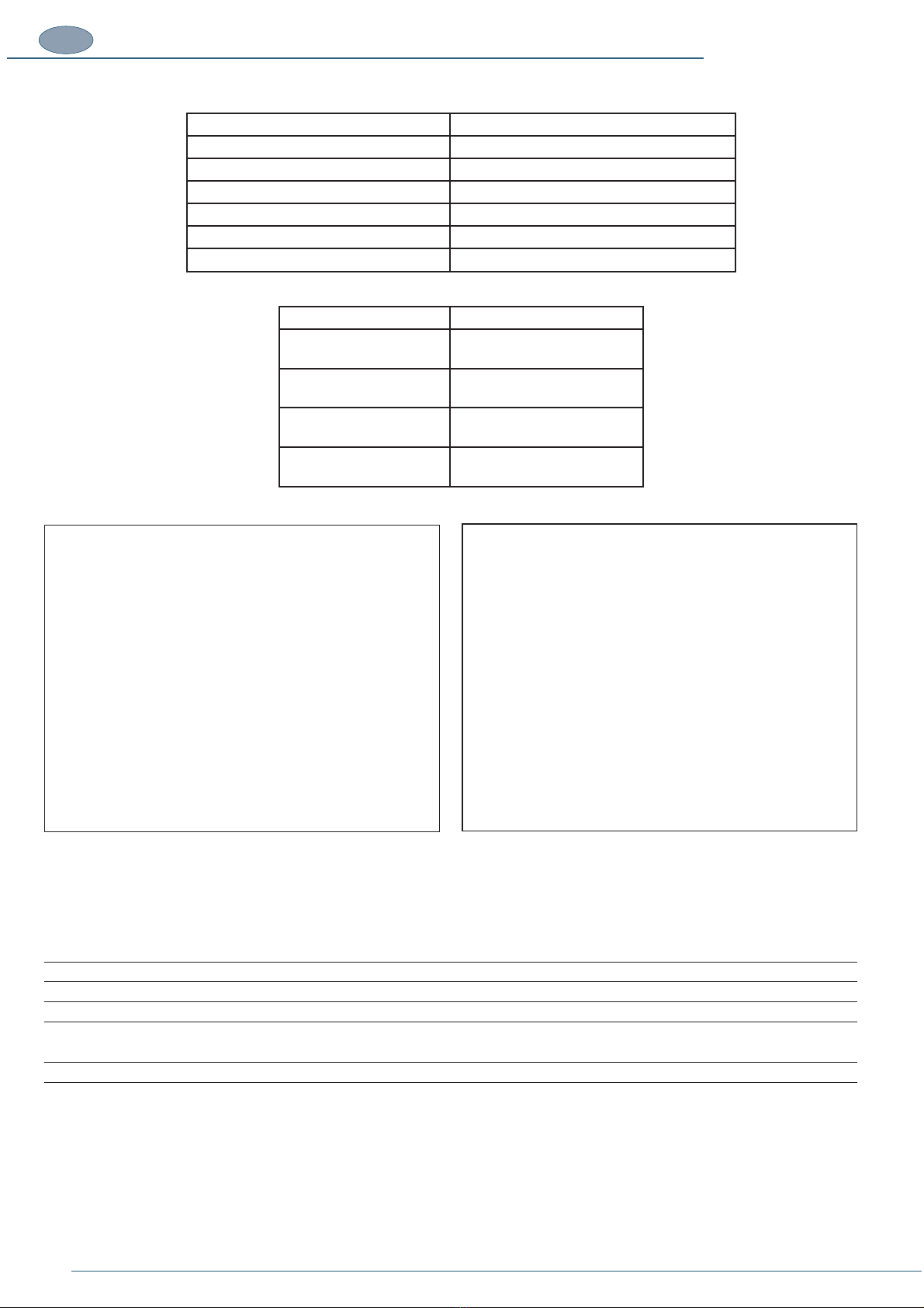
Ref.
A
B
C
D
GUARDS /
PROTECTIVE
DEVICES – POSITION
Moveable guard
Fixed guard
Fixed guard
TYPE OF SAFEGUARDED
HAZARD
The transparent
polycarbonate panel stops
access to the magazine on
the U600 model
Rear steel sheet panel
secured in place with
screws to prevent access
to electromechanical and
electronic components.
Polycarbonate panel secured
to metal supports which
on the relative knobs, to
prevent access to the vertical
clamping unit.
Front steel sheet panel
secured in place with
screws to prevent access
to electromechanical and
electronic components.
A
B
C
D

TRANSLATION OF THE ORIGINAL INSTRUCTIONS (Keep for future reference)
Codice Documento Rev. Data di salvataggio Data di stampa
U500 - U600 ISTRUZIONI 02 04/11/2015 04/11/2015
EN
10
1.11. DESCRIPTION OF THE MACHINE
The machine is equipped with an electronic control system which is capable of performing the most varied operating cycles extremely
quickly. Thousands of operating programs, corresponding to the different types and dimensions of the frames being made, can be stored
in the machine’s memory.
use special Alfagraf V-nails with “Pulling Power” effect or standard V-nails.
1 working bench, complete with:
1 base which supports the working bench, complete with:
1 control console with touch screen, complete with:
The machine’s AUTOMATIC FUNCTIONS, programming and operating sequence are electronically controlled.
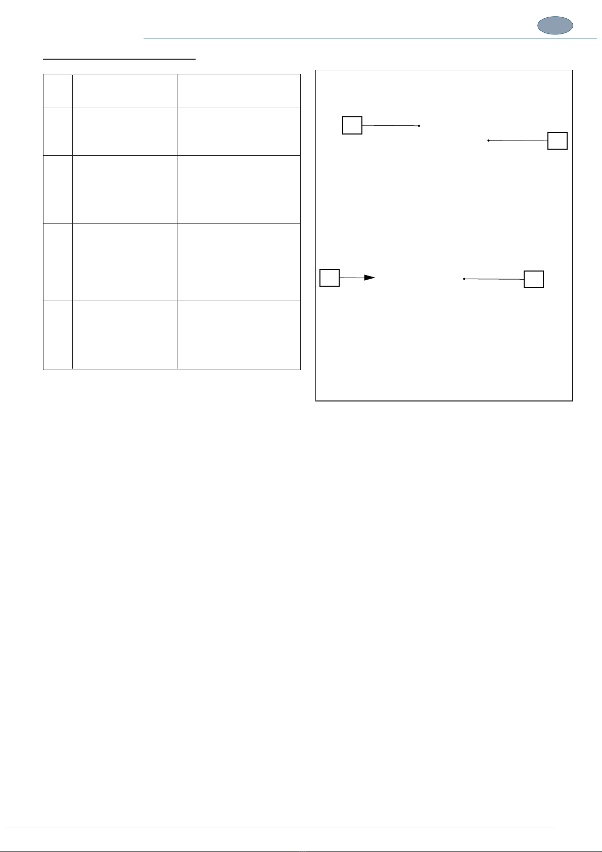
1.12. MAIN MACHINE COMPONENTS
Ref.
A
B
C
D
E
DESCRIPTION
Pneumatic panel
Electrical panel
Control console touchscreen panel
Working bench
Pedal button
C
E
D
A
B
TRANSLATION OF THE ORIGINAL INSTRUCTIONS (Keep for future reference)
Codice Documento Rev. Data di salvataggio Data di stampa
U500-U600 ISTRUZIONI 02 04/11/2015 04/11/2015 EN
11
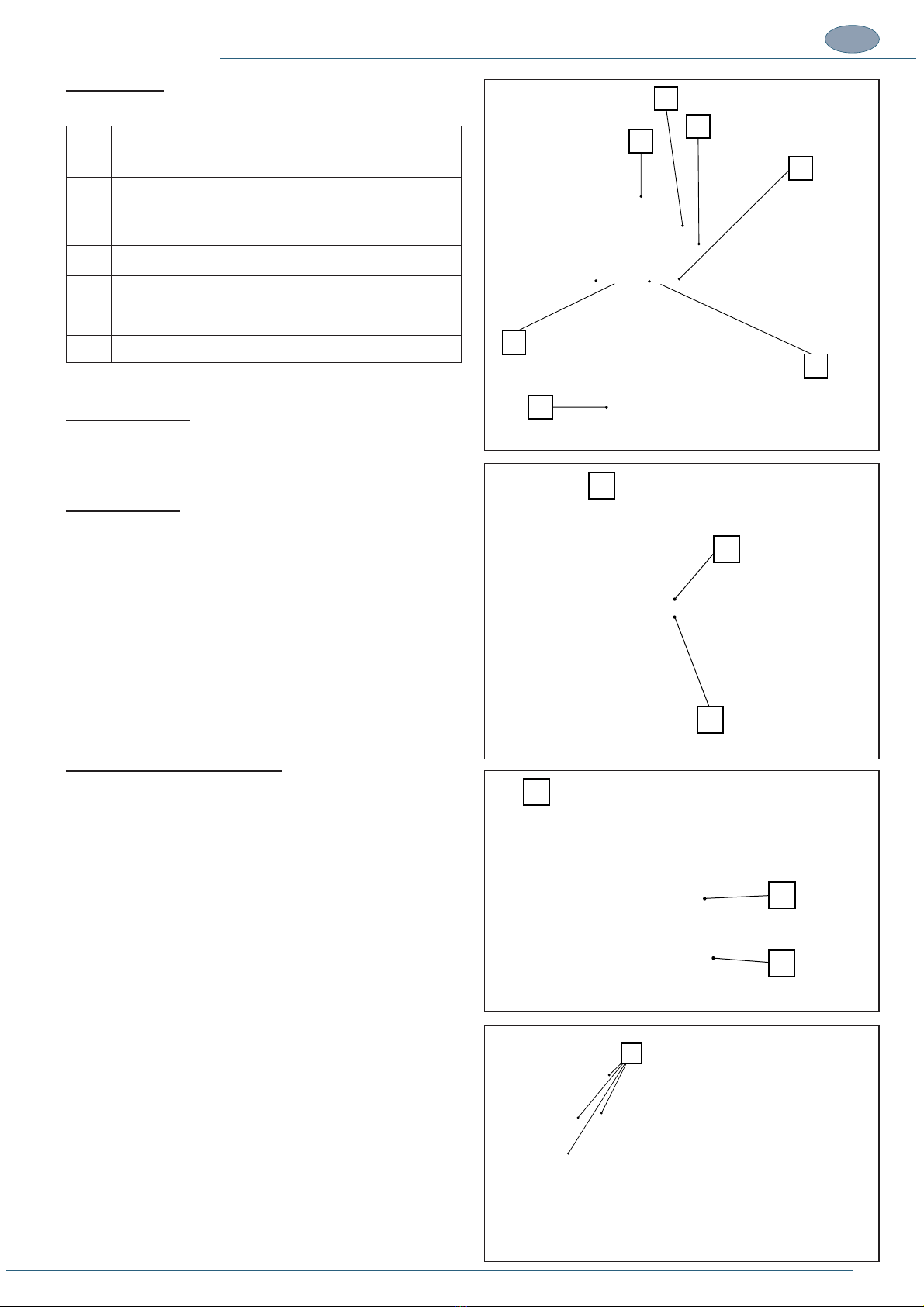
Working bench
The working bench is made up of the following main parts:
Ref.
A
B
C
D
E
F
DESCRIPTION
V-nail magazine
Vertical stopper unit support
Vertical clamp unit
Alignment guides
Horizontal clamping unit
Head sliding slot
V-NAIL MAGAZINE
There are two types of V-nail magazine:
Single magazine:
In the U500 machine (G), the single magazine (H) can hold V-nails
of different heights but only one V-nail size can be used at a time,
depending on the nailing head installed.
When the size of the V-nails is changed the nailing head must also
be switched over to match the V-nails used.
The V-nails are held in position by the V-nail pusher device (I).
In the U600 machine (L) machine, the operator has 5 magazines
(N) he can use, all mechanically set up to customize the type of
V-nail to be used depending on the user’s needs.
Each has a value stamped on it which corresponds to the height
of the V-nail it can hold.
There is no need to switch over the nailing head.
The magazine translates automatically, punctually supplying the
V-nail of the correct size depending on the program being executed
by the PLC.
The V-nails in each magazine are held in position by the relative
V-nail pusher device (M).
(O) in each single magazine channel.
B
C
D
E
F
D
A
O
I
H
G
M
L
N

TRANSLATION OF THE ORIGINAL INSTRUCTIONS (Keep for future reference)
Codice Documento Rev. Data di salvataggio Data di stampa
U500 - U600 ISTRUZIONI 02 04/11/2015 04/11/2015
EN
12
VERTICAL CLAMP UNIT OF THE MOULDINGS
Vertical clamp unit with double hydraulic stopper
This unit has been designed to immobilize the mouldings and counteract the opposing force applied by nailing, consequently it is important
to position the stoppers in line with the direction of the nailing head; if this is not the case the V-nails may not be inserted completely if
the mouldings lift slightly.
onto a connector on top of each actuator.
is useful for achieving correct alignment of the stoppers, even when the mouldings have uneven surfaces.
executed. For this procedure please refer to the heading MECHANICAL ADJUSTMENTS.
If you wish to use only one stopper, for example on narrow frames,
it is possible to block the stem using the special handle (E, H).
The vertical clamp unit is made up of the following main parts:
B. hydraulic cylinders
C. handle for installation of the unit on the support
D. handle for locking cylinder forward/back movement
E. handle for locking the cylinder stem
F. screw for locking cylinder up/down movement (one on each
cylinder)
G. rear stopper
H. handle for locking the cylinder stem
I. handle for locking cylinder forward/back movement
L. front stopper
Single stopper unit
The unit is made up of a mechanical stopper in vulcolan (O), located
at the base of the punched rod (M), which can be positioned at
various heights, depending on the measurements of the frame
being handled, and translated in the direction of motion of the nailing
unit by means of the fork support (S). The unit is supported by a
crosspiece (Q) secured to 2 pneumatic pistons which the operator
uses to control the vertical movement.
The mechanical stopper can be replaced with a support for magnetic
stoppers.
The single vertical clamp unit is made up of the following main parts:
M. punched rod which allows the operator to position the stopper
O. mechanical Vulcolan stopper
P. Click knob
Q. rod support arm
R. stems activated vertically by the pneumatic actuator
stopper along the stroke of the nailer unit.
H
I
A
B
C
D
F
GL
E
P
S
Q
R
M
N
O

TRANSLATION OF THE ORIGINAL INSTRUCTIONS (Keep for future reference)
Codice Documento Rev. Data di salvataggio Data di stampa
U500-U600 ISTRUZIONI 02 04/11/2015 04/11/2015 EN
13
Alignment guides
rest which can be adapted to match the frame profile and
compensate for the narrow cutting tolerances on the mouldings
positions for creating 90° corners (4-sided frames), 120° corners
(6-sided frames) and 135° (8-sided frames).
The alignment fences are made up of the following main parts:
C. fence body;
angles 120°/135°;
The rod clamp is a horizontal blocking element which, activated
The rod clamp is made up of:
H. knob for securing the rod to the actuator installed below the
working bench;
the mouldings.
Nailing head
The nailing head ensures precision insertion of the V-nails in the
frame. There are two types of nailing head, the one used on the
U500 machine (P), different for each typ of V-nail, and the one
used on the U600 machine with magazine (L) which is for all V-nail
heights.
On the U500 machine the head is marked with a number (Q) which
indicates the height of the V-nails it can use. Each time a different
kind of V-nail is used the head must be switched accordingly. Usually
the machine is supplied with three different nailing heads for use
with the most commonly used V-nails.
In the U600 machine, the nailing head does not need to be changed
when different V-nails are used. It is marked with the code MC (M).
The nailing head is installed on the L-block support (N) which is
in line with the hammer and during the nailing action it is moved
to insert the V-nails in accordance with the number and spacing
entered in the program.
L. nailing head for U600 Machine;
M. code stamped on the U600 model
N. L-block support
P. nailing head for U500 Machine
Q. this number must match the size of the V-nails being used
GHI
LM N
O
QP
R
C
D
A
CD
B
F
E

TRANSLATION OF THE ORIGINAL INSTRUCTIONS (Keep for future reference)
Codice Documento Rev. Data di salvataggio Data di stampa
U500 - U600 ISTRUZIONI 02 04/11/2015 04/11/2015
EN
14
bench needs to be increased by installing the two side extensions
(A) (optional).
perfectly aligned with the working bench, see heading ASSEMBLY
OF SEPARATELY SHIPPED UNITS.
A. right extension
B. left extension
The machine is designed to be STATIC, i.e. it must be installed
structure so that it remains stationary during operation.
The machine is LOADED AND UNLOADED MANUALLY:
I. MANUAL POSITIONING OF THE MOULDINGS to be
and locked
ii. MANUAL REMOVAL OF THE ASSEMBLED MOULDINGS from
2. INSTALLATION
2.1. STORAGE
The machine, intended for indoor installation must be stored, if necessary, in well ventilated storage facilities and protected from dust.
oxidation caused by weather conditions.
In the case of prolonged inactivity the machine must be stored with all necessary precautions taken based on the location and expected
storage times:
1. Store the machine in an enclosed place.
2. Protect the machine from impact and stress.
3. Protect the machine from humidity and excessive temperature differences (refer to the table below).
4. Do not allow corrosive substances to come into contact with the machine.
5. Check that the pack has not been damaged and that it is perfectly dry.
including rain, snow and hail, and it must be accessible exclusively to authorized personnel.
The machine is protected in such a way as to withstand the temperatures, humidity and vibration levels typically associated with transport
and storage.
Ambient
temperature
Storing
temperature
Relative humidity
Vibrations
Atmospheric
pressure
-25- +40 °C / -13 -+104°F (if the electric material has a protection rating of at least IP54)
0- +40 °C / 32 -+104°F (if the electric material has a protection rating below IP54)
-25- +55 °C / -13 -+131°F (if the electric material has a protection rating of at least IP54)
0- +55 °C / 32 -+131°F (if the electric material has a protection rating below IP54)
100% at a temperature of +25°C / 77°F (if the electric material has a protection rating
of at least IP54)
Lower than 50% at a temperature of +40°C / 104°F
Lower than 90% at a temperature of +20°C / 68°F (if the electric material has a protection
rating below IP54)
5.9 m/s2 (0.6G) or higher
900 mbar or more
Avoid places where
there may be
unexpected changes
in temperature
which could lead
to the formation of
condensate or freezing.
Storage temperature is construed as a short-term value, e.g. during transportation. Condensation or freezing normally occurs in sites
A
B
TRANSLATION OF THE ORIGINAL INSTRUCTIONS (Keep for future reference)
Codice Documento Rev. Data di salvataggio Data di stampa
U500-U600 ISTRUZIONI 02 04/11/2015 04/11/2015 EN
15
2.2. CHECKS ON RECEPTION
NOTES
Administrative check
1. Crate number and number of packs.
2. Weight and size
3. Correspondence of information on shipping document with the material effectively delivered (description, serial number, etc). The
4. Check correspondence between shipping document data and the order.
Technical check
1. Condition and intactness of packaging.
2. Check that the packaging shows no signs of visible damage caused during transport and handling operations.
All the above checks must be performed by inspection in the presence of the shipping agent’s delivery person. If any damage is noted
or the supply is incomplete or incorrect, inform the manufacturer’s sales department immediately.
NOTES
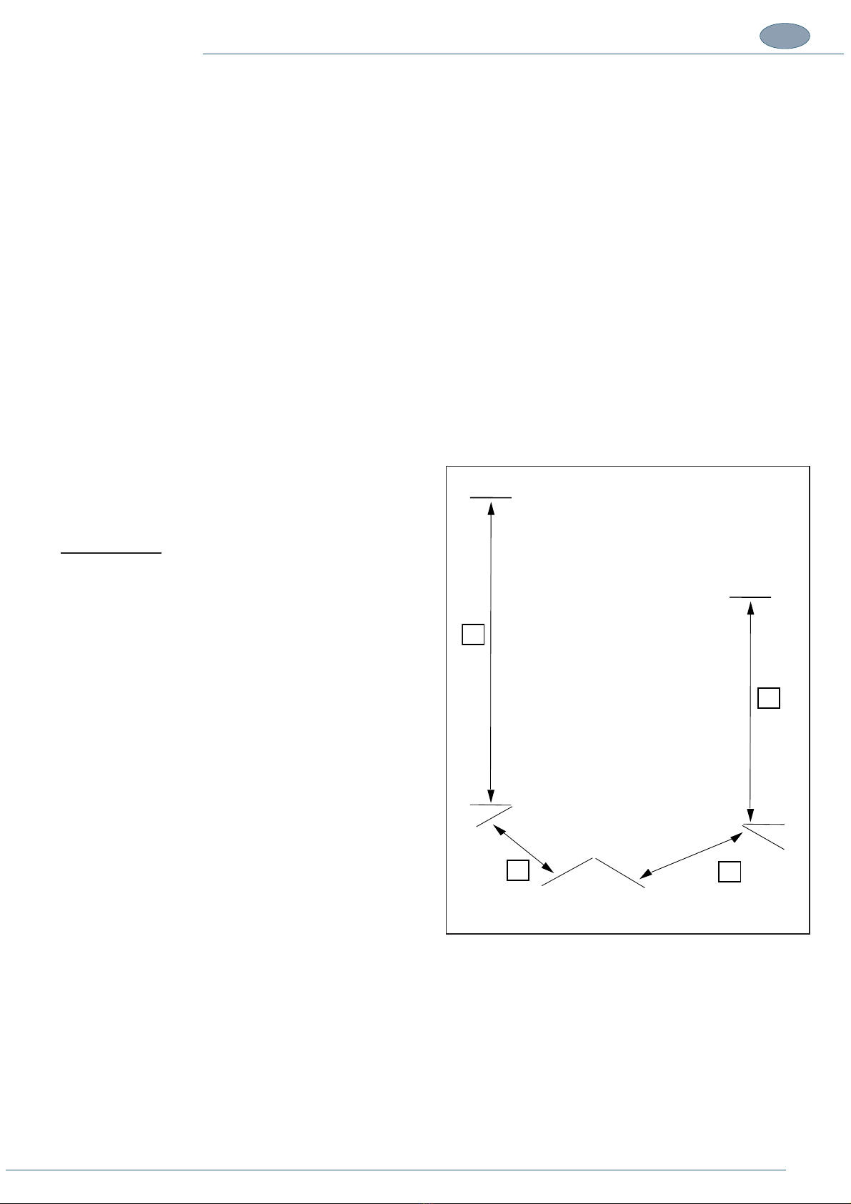
2.3. TRANSPORT, LIFTING AND HANDLING
Dimensions, weight and handling of individual machine parts
MACHINE BODY
Machine height .........................................A = 1500mm - 11’’ 1/16
Machine width ........................................... B = 770mm - 6’’ 5/16
Machine depth ............................................ C = 770mm - 6’’ 5/16
. D = 1000mm - 3’’ 3/8
Weight ................................................................................. 140 kg A
D
B
C
TRANSLATION OF THE ORIGINAL INSTRUCTIONS (Keep for future reference)
Codice Documento Rev. Data di salvataggio Data di stampa
U500 - U600 ISTRUZIONI 02 04/11/2015 04/11/2015
EN
16
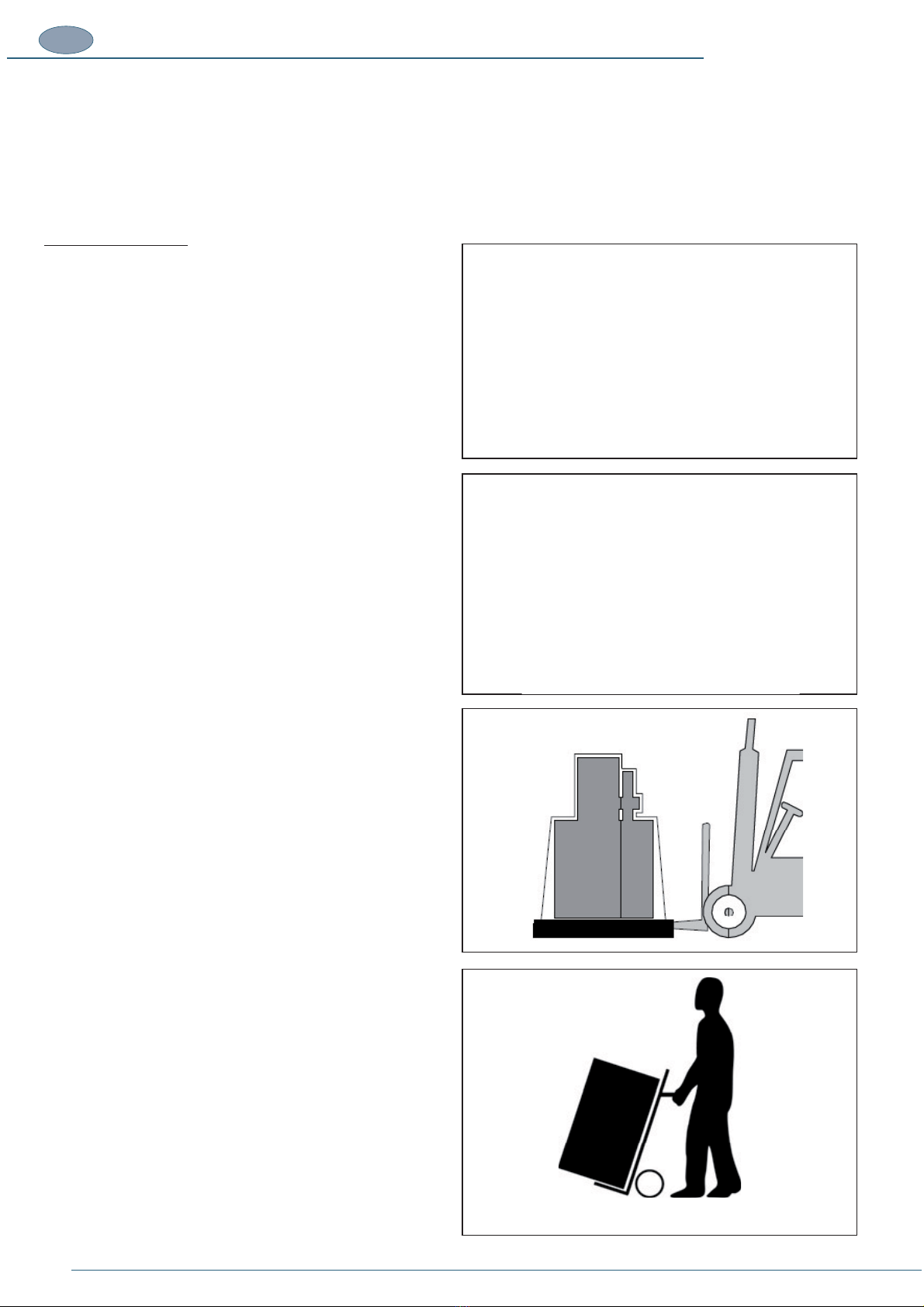
2.4. LIFTING AND HANDLING
DANGER – CAUTION
checked beforehand to obtain information about the necessary clearances and dimensions, including the essential
space required for installation procedures.
moves out of the way.
Lifting FROM BELOW
The operations to lift and handle the machine must be carried out
of the chosen equipment are inserted correctly under the packaging
or machine structure. Make sure the load is evenly balanced.
The forks on the equipment used to lift and handle the machine
must be in good, undamaged condition and be at least 1500 mm
long.
When the machine is packaged on a pallet it must be moved by a
forklift.
When the machine is unpacked it can be moved on a two-wheel
trolley.
1500 mm
This manual suits for next models
1
Table of contents
Other FLETCHER Industrial Equipment manuals


Popular Industrial Equipment manuals by other brands


Scotsman
Scotsman Prodigy Elite MC0322 Service manual

Graco
Graco 210067 Instructions-parts list

Eaton
Eaton GD4-050-BD3 Instruction leaflet

SMC Networks
SMC Networks SY3000 SERIES manual

Jäger
Jäger Z42-D160.20 S2A manual

Reliable
Reliable Double Interlock Preaction System D Instructions for installation, operation care and maintenance


