7
2. Installation:
The Booster can be mounted using the 4 screw holes molded into the base plate.
3. Connection:
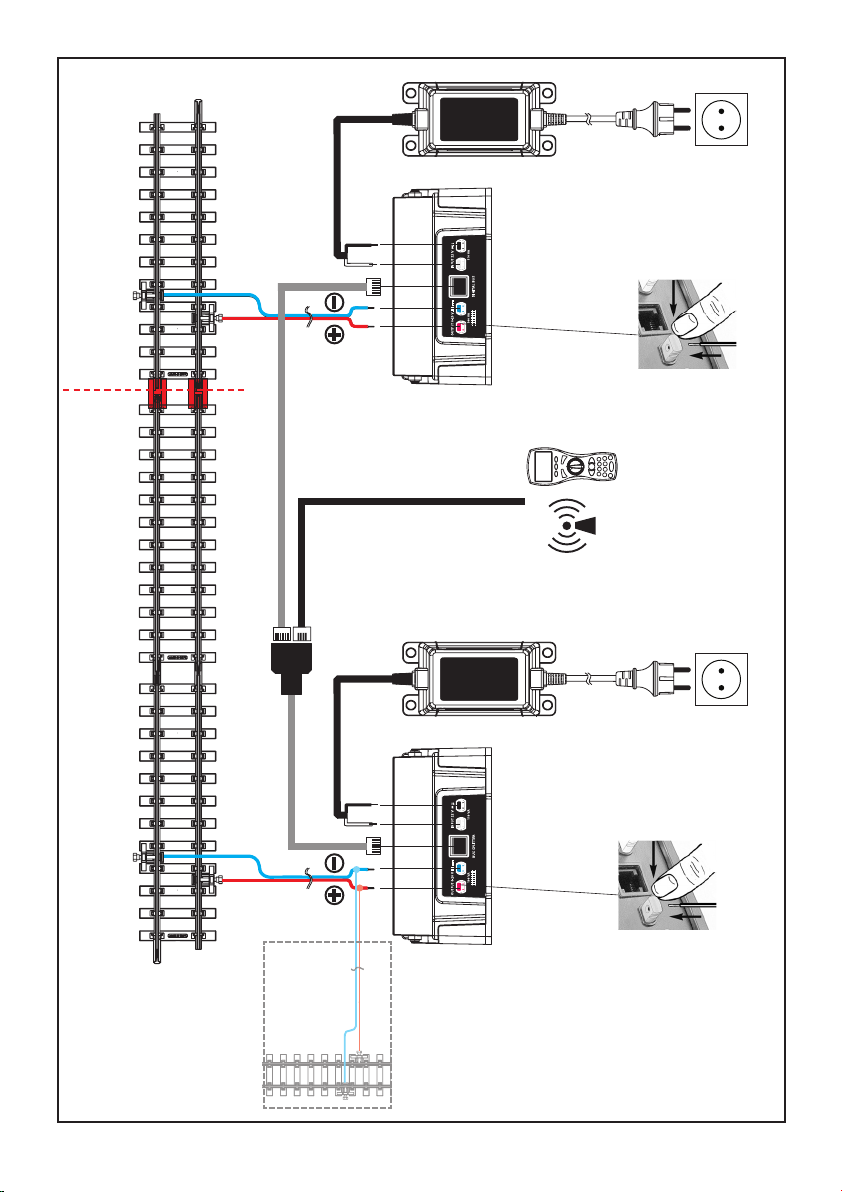
Make sure that the track section (block) you wish to operate with the Booster is completely isolated electrically
from all other powered track sections. PIKO #35292 Insulated Rail Joiners are recommended for this. Each
device (Booster or Digital Central Station) supplies its own track section. Connect only one device to each
section.
Important! Pay careful attention to connecting the Digital Central Station and all Boosters to the track in
the same order (for example, connect all blue terminals to the “left” track rails and all red terminals to
the “right” track rails). If a pair of terminals is connected in the opposite order, a short circuit will occur
when a train passes over the gap from one block to another.
1. Lift up the Booster’s clear plastic rear cover. Press the color-coded spring-terminals inwards and insert the
bare wire ends into the holes in the terminals. Releasing pressure on the terminal secures the wire. Connect
the red and blue wires from a #35270 Track Power Clamp to the red and blue terminals on the Booster.
Connect the black and white wires from the power supply to the black and white terminals on the Booster.
(images 1, 2 and 4)
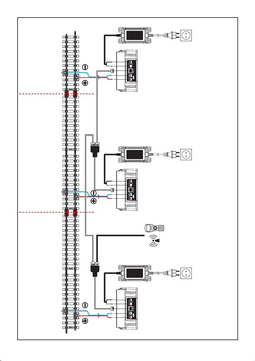
2. Important! Use only the included gray data cables for connecting the Digital Central Station and Boosters.
The Navigator Remote or Wireless Receiver is connected using a black data cable.
A maximum of 4 Boosters can be connected to one Digital Central Station, allowing up to 20 amps of total
power capacity for the layout.
1. Connect one gray data cable plug to the data socket in the center of the Digital Central Station’s rear panel.
2. Connect the other end of this cable into one socket of the included Bus Splitter, then connect the gray cable
from the Bus Splitter into the data socket in the center of the Booster’s rear panel. More Boosters can be
connected into the remaining socket on the Bus splitter, using an additional gray data cable and Bus Splitter
for each Booster.
One socket always remains free on the Bus Splitter of the last Booster. Connect the black data cable of the
Navigator Remote or Wireless Receiver into this socket.
Long Track Runs
With large layouts, such as on a garden railway, it is advisable to install additional track power feeds at intervals
(Image 1, Optional Additional Track Power Feeds). This ensures good power supply and reliable data
communication. Make sure to connect the wires in the same order. Make wire extensions using a high-quality cable,
with a cross section of at least 0.75 mm² (18AWG in America). Take care to connect each wire to the correct rail.
4. Operation
Control is accomplished only through the Digital Central Station and the instructions given to it from control
devices such as the Navigator Remote. The Booster is ready for operation as soon as the Digital Central
Station is powered up and ready. The two LEDs indicate the operation mode and status: (image 3)
Yellow/Orange LED (right):
LED Off = Operating Mode 1 – without whole-layout short-circuit feedback (factory default setting)
LED On = Operating Mode 2 – with whole-layout short-circuit feedback
Red/Green LED (left):
Constant Green: Fully ready for operation
Blinking Green: Standby mode – the Booster receives no data from the Digital Central Station
Blinking Red: Short-circuit, Overload or manual Emergency Stop
Constant Red: Overheating
Blinking Red/Green: Emergency Stop mode – ready for configuration
35015-90-7000_v2 17.06.2011 8:04 Uhr Seite 7