1 ULAD 31 Converter Features
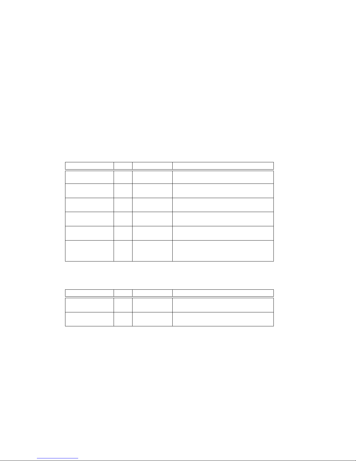
Technical Specifications of ULAD 31 :
Quantity Value Units
Supply voltage 5 to 12 VDC
Max. single unit supply current 100 mA
Max. supply current in power distribution mode 500 mA
Absolute max. analog input voltage ±15 V
Number of analog inputs (continuous acquisition) 1
Analog input multiplexer ( 2 ch. ) (optional)
Sampling frequency - basic rate 10 Hz
– optional selectable frequencies 20, 25, 40, 50, 80,
100
Basic input voltage range (gain ×1) ±10 V
Software selectable gain and range reduction ×1,×2,×4, · · · ,×64,×128
AD converter resolution for basic rate 18 to 20 bit
Width of input software filter from 1 to 64 samples
Number of digital inputs/outputs 4 / 4
Sample valve position/mark detection Yes
Communication interface RS-485
Protocol uLan
Communication baud rate 19200 Baud
2 Setup
ULAD 31 device can be connected to control/acquisition computer by USB cable or through
uLan network. To connect ULAD 31 to computer by means of uLan network another
ULAD 31, uLan to USB converter or uLan RS-485 card is required to interface uLan RS-
485 link to the PC. In the case of direct USB connection, ULAD 31 is powered by computer
over USB cable. If multiple ULAD 31 should be connected to one PC then they should be
interconected by uLan cable and only one device connected to the PC. Up to 3 more inter-
connected devices can be powered through that ULAD 31 device which is connected to the
PC if power distributed mode is selected and cables for power distribution is used (typically
white cables). If long distance or more devices are used then the power supply adapter has
to be used to provide power for other devices. Device can be even switched to USB device
disable mode to use USB connection only for power up. Independed power adapter with
USB terminal can be used to provide power supply for distant units.
2.1 Configuration switches
ULAD 31 is equipped by two switches. SW1 enables USB device interface. If disabled,
computer does not see the device but device can be powered through USB. The SW2 select
high current USB mode to receive enough power to distribute it to other interconnected
devices.
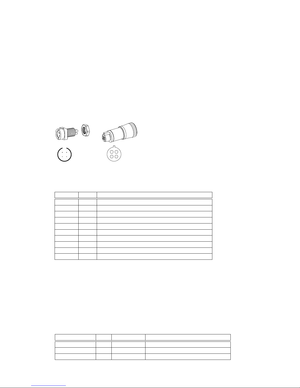
2.2 Device connectors and terminals
The next connectors can be found on the ULAD 31 device
USB connector used to connect device to a computer or to power device by power adapter
with USB terminal
2