Die Muting-Lampe PIT si1.2
Die Muting-Lampe ist bestimmt für den
Einsatz als Signalleuchte im Muting-Betrieb.
Wenn die Funktion der Lampe durch ein
Auswertegerät, das Kategorie 4 nach
EN 954-1 erfüllt, überwacht wird, kann unter
Berücksichtigung der notwendigen
Schaltungsmaßnahmen die Muting-Lampe
ebenfalls bis Kategorie 4 eingesetzt werden.
Zulässige Auswertegeräte sind:
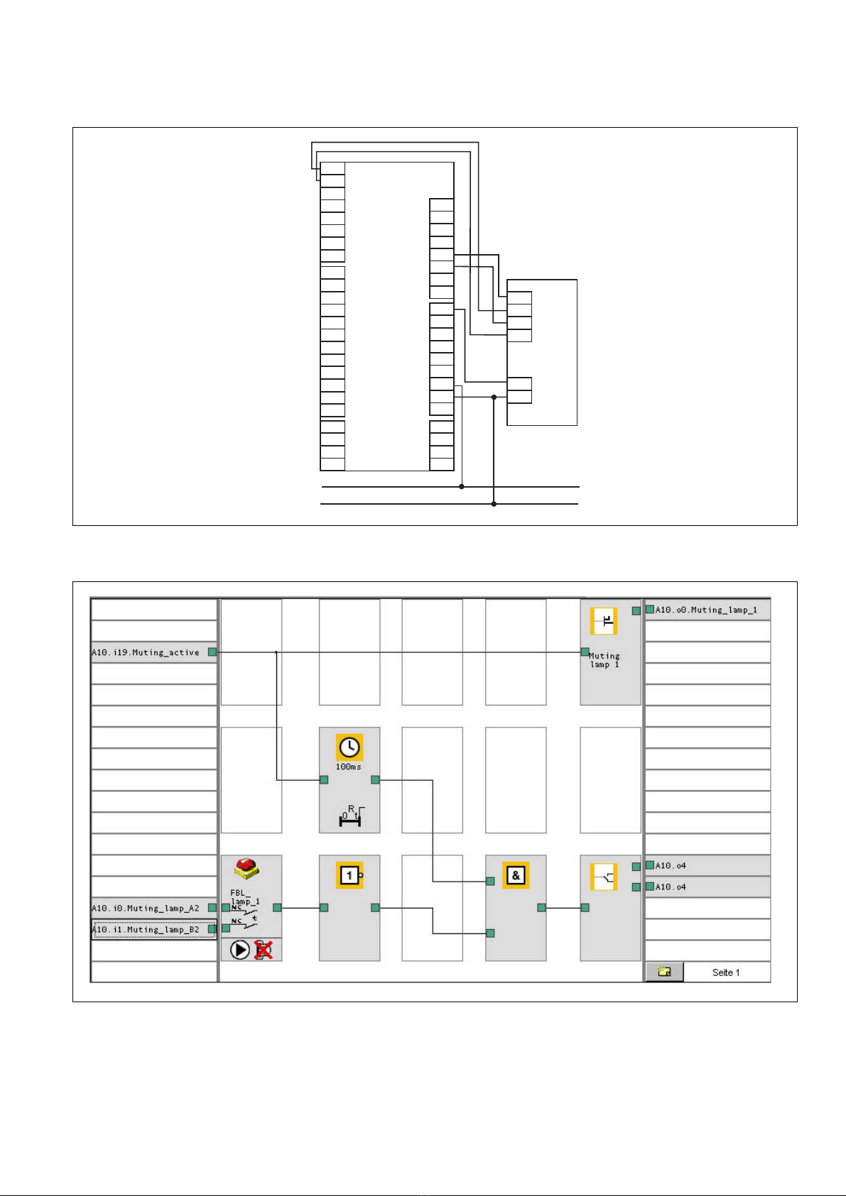
• das modulare Sicherheitssystem
PNOZmulti (Anwendungsbeispiel
s. technischer Katalog PNOZmulti)
• Sicherheitssteuerungen der Systemfamilie
PSS
• Sicherheitssteuerungen der Systemfamilie
PSS mit SafetyBUS p-Anschluss
Zu Ihrer Sicherheit
Beachten Sie die nachfolgend aufgeführten
Sicherheitsbestimmungen:
• Installieren und nehmen Sie das Gerät nur
dann in Betrieb, wenn Sie mit dieser
Betriebsanleitung und den geltenden
Vorschriften über Arbeitssicherheit und
Unfallverhütung vertraut sind.
• Verwenden Sie das Gerät nur gemäß
seiner Bestimmung. Beachten Sie dazu
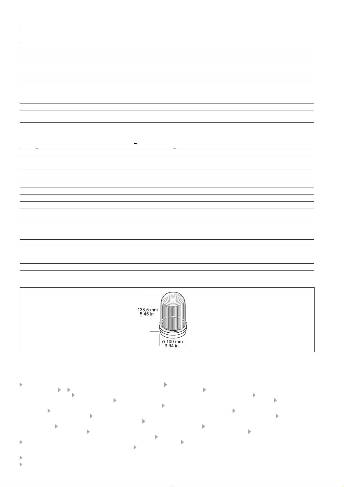
auch die Werte im Abschnitt "Technische
Daten".
Beachten Sie unbedingt die Warnhinweise in
den anderen Abschnitten dieser Anleitung.
Diese Hinweise sind optisch durch Symbole
hervorgehoben.
Wichtig: Beachten Sie die Sicher-
heitsbestimmungen, sonst erlischt
jegliche Gewährleistung.
Gerätebeschreibung
• Muting-Lampe nach EN 61496
• 2 Halbleiterausgänge zur Funktions-
überwachung
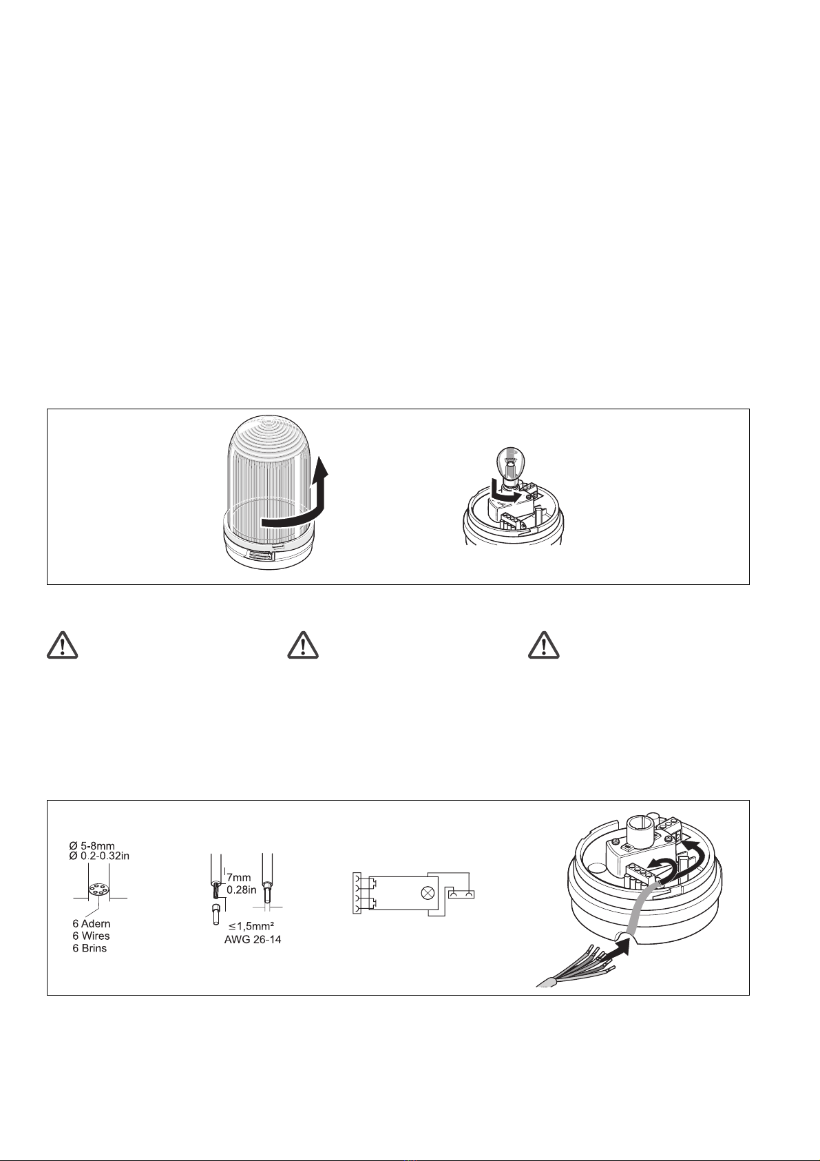
Lieferumfang:
• Muting-Lampe inklusive Glühbirne
• Befestigungswinkel
• 2 Schrauben
Funktionsbeschreibung
Während des Muting-Betriebs muss der
Bediener auf die Gefahr, die durch die
Überbrückung der Sicherheitsfunktion
entsteht, aufmerksam gemacht werden.
Speziell für diesen Einsatz ist die Muting-
Lampe PIT si1.2 konzipiert. Sie leuchtet,
sobald der Muting-Betrieb gestartet wird.
Zwei Halbleiterausgänge ermöglichen die
Funktionsüberwachung der Lampe.
• Normalbetrieb:
Wird die Lampe nicht angesteuert, führen
beide Ausgänge Low-Signal. Wird die
21 039-01
PIT si1.2
4D Betriebsanleitung
4GB Operating instructions
4F Manuel dutilisation
La lampe muting PIT si1.2
La lampe muting est destinée à être utilisée
comme voyant de signalisation en mode
muting. Si le fonctionnement de la lampe est
surveillé par un appareil conforme à la
catégorie 4 selon la norme EN 954-1, la
lampe muting peut être mise en œuvre
également jusqu’à la catégorie 4, sous
réserve du respect des branchements
nécessaires. Les appareils de surveillance
autorisés sont les suivants :
• le système modulaire de sécurité
PNOZmulti (voir le catalogue technique
PNOZmulti pour les exemples d’application)
• les automates de sécurité de la gamme
PSS
• les automates de sécurité de la gamme
PSS avec raccordement SafetyBUS p
Pour votre sécurité
Vous êtes tenu de respecter les prescriptions
de sécurité suivantes :
• Vous n’installerez l’appareil et ne le
mettrez en service qu’après vous être
familiarisé avec le présent manuel
d’utilisation et les prescriptions en vigueur
sur la sécurité du travail et la prévention
des accidents.
• N’utilisez l’appareil que conformément à
l’usage auquel il est destiné. À ce sujet,
respectez les valeurs indiquées dans les
"Caractéristiques techniques".
Respectez impérativement les avertisse-
ments dans les autres paragraphes du
présent manuel d’utilisation. Ces avertisse-
ments sont signalés par des symboles visuels.
Important : respectez les consignes
de sécurité, sinon la garantie devient
caduque.
Description de l’appareil
• Lampe muting selon EN 61496
• 2 sorties statiques pour les fonctions de
surveillance
Contenu de la livraison :
• Lampe muting, ampoule incluse
• Équerre de fixation
• 2 vis
Descriptif du fonctionnement
Pendant le mode muting, l’attention de
l’utilisateur doit être attirée sur le danger
résultant du shuntage de la fonction de
sécurité. La lampe muting PIT si1.2 est
spécialement conçue à cet effet. Elle
s’allume dès que le mode muting est activé.
Deux sorties statiques permettent la
surveillance du fonctionnement de la lampe.
• Marche normale :
Lorsque la lampe n’est pas commandée,
les deux sorties présentent un signal Bas.
The PIT si1.2 muting lamp
The muting lamp is intended for use as an
indicator in muting mode. If the function of
the lamp is monitored by an evaluation
device that meets category 4 in accordance
with EN 954-1, the muting lamp can also be
used up to category 4 if the necessary circuit
measures are taken into account. Permissi-
ble evaluation devices are:
• The modular safety system PNOZmulti (for
application example see technical
catalogue for PNOZmulti)
• Programmable safety systems in the PSS
range
• Programmable safety systems in the PSS
range with SafetyBUS p connection
For your safety
Please note the following safety regulations:
• Only install and commission the unit if you
are familiar with both these instructions
and the current regulations for health and
safety at work and accident prevention.
• Only use the unit in accordance with its
intended purpose. Please also take note of
the values in the "Technical details"
section.
You must take note of the warnings given in
other sections of these operating instructions.
These are highlighted visually through the
use of symbols.
Notice: Failure to keep to these safety
regulations will render the warranty
invalid.
Unit description
• Muting lamp in accordance with EN 61496
• 2 semiconductor outputs for function
monitoring
Range:
• Muting lamp including bulb
• Fastening bracket
• 2 screws
Function description
In muting mode the operator must be made
aware of the danger that results from the
suspension of the safety function. The
PIT si1.2 muting lamp is specially designed
for this purpose. It illuminates as soon as
muting mode is enabled. Two semiconductor
outputs enable the function of the lamp to be
monitored.
• Normal operation:
if the lamp is not operated, both outputs
are low. If the lamp is operated and