Pima TD-600/SAT-6 User manual

TD-600/SAT-6
Universal Standalone Radio Communicator
Installation Guide
PIMA Electronic Systems Ltd.

TD-600/SAT-6 Installation Guide
2
Table of contents
Preface........................................................................................................................... 3
Features ............................................................................................................................. 3
Safety instructions............................................................................................................... 3
Tech specifications .............................................................................................................. 3
The SAT-6 module.......................................................................................................... 4
Installation .................................................................................................................... 5
Mounting guidelines ............................................................................................................ 5
Mounting the box................................................................................................................ 5
Battery jump-start............................................................................................................... 5
Connecting to power ........................................................................................................... 6
Programming the SAT-6 ................................................................................................ 8
Report codes ...................................................................................................................... 9
Changing the Technician code ........................................................................................... 10
Signs in this guide
Warning
Note
Default Codes
Master: 5555
Installer: 1234

Preface
3
Preface
This guide will help you through the installation and configuration of the TD-600/SAT-6, a PIMA
universal standalone radio communicator, designed to allow any alarm system to relay
transmissions to the CMS (Central Monitoring Station), via our long range VHF/UHF radio
transmitters (TRV/TRU-100).
The TD-600/SAT-6 can be programmed via a PIMA LCD keypad and the COMAX software.
The TD-600/SAT-6 is supplied in a special enclosure, with a transformer and a tamper switch.
Features
The control panel is based on PIMA’s Captain 6 system, with 6 dry contact inputs.
Support in two radio frequencies
Support in two ID accounts.
Integrated PSTN dialer.
Quick transmit time saves air time and reduces the chance for jamming.
Support in PAF/NPAF protocols, as well as other protocols.
Secured connection against cut and short.
Programming via any PIMA LCD keypad and the COMAX program.
Safety instructions
Make sure the SAT-6 is not connected to power (AC & DC) before installation.
Do not mount the TD-600 near a metal wall or ceiling.
Make sure the radio antenna is not mounted in parallel or too near the detectors’ wires.
Mount the antenna only after installing the radio transmitter.
Make sure the antenna is vertically mounted.
Before performing transmission tests, close the enclosure.
Tech specifications
AC power
14VAC/2A
TRV/TRU-100
10mA/1A
Battery
Lead-acid, 12VDC, up to 7.5A/h
Temperature (Celsius)
-10° to +50°
Humidity
75% (non-condensed)

TD-600/SAT-6 Installation Guide
4
The SAT-6 module
Figure 1. The SAT-6 diagram
No.
Terminal/
Connector
Description
1
(+)/(-)
Power supply for PIR/ultrasonic/etc., detectors
2
Z1-Z6
6 inputs for dry contact detectors & (-) terminal
3
KEYPAD
A Molex connector for quick connection of the technician keypad
4
EGND
Earth Ground terminal. Can be used in areas of severe electrical
activity (abnormal levels of lightning or electrical discharge).
When using PIMA’s integrated transformer, earth ground is not
required. Only when using external transformer and lightning
conditions are severe, the EGND terminal can be used.
Connect the terminal to earth grounds, such as metal cold water
pipe or AC power outlet ground
5
Transmitter
A connector to the TRV/TRU-100 long range radio transmitters and the
GSM-200 cellular module
6
Backup
Battery wires
Red: (+)
Black : (-)
7
AC
14-16 VAC Voltage input
The cross-section area of the AC cable must be at least 0.75mm2

Installation
5
Installation
Make sure the TD-600 is not connected to AC and battery power.
Mounting guidelines
Follow the next guidelines before mounting the TD-600 box:
Do not mount the box close to metal wall or ceiling.
Do not pass the zone wires next to the antenna.
Install the antenna only after installing the box.
Make sure the antenna is vertically mounted.
Before performing transmission tests, close the box.
Mounting the box
To mount the box, follow the next steps:
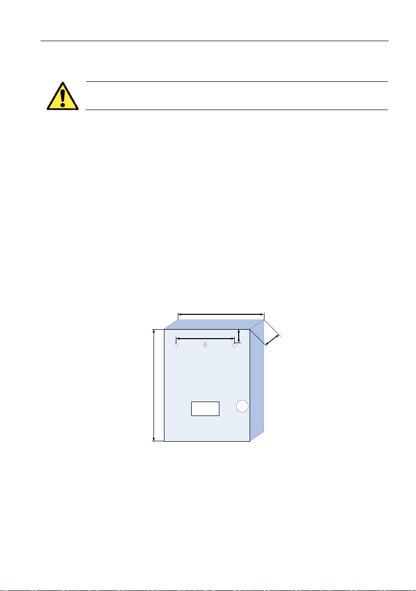
1. Use the next diagram to make 2 holes to hang the box.
2. For plaster wall, use 2 matching anchors and screws (not supplied).
3. For wood wall, use 2 matching screws (not supplied).
4. For brick wall, drill two holes, insert anchors and fasten screws (not supplied).
Figure 2. The TD-600, back view
Battery jump-start
During AC power loss, if the battery’s voltage drops below 10.5V, it is disconnected to prevent full
battery discharge. This feature extends the battery life cycle.
Because of this, the control panel cannot be powered up using only the battery, and must be
connected to AC voltage first.
When AC voltage is not available, you can power up the panel by following the next steps:
a) Connect the SAT-6 to the Battery.
33/33.5 cm
3.5 cm
17.5 cm
9 cm
26/26.5 cm

TD-600/SAT-6 Installation Guide
6
b) Briefly short the Battery’s (-) terminal to the control panel’s (-) terminal. See the diagram.
c) The control panel will now power up.
Connecting to power
AC voltage must be supplied from a transformer (2A/16VAC). Do not
connect the SAT-6 to direct power source!
The system should be connected to an automatic circuit breaker.
If earth grounding is required, connect it to the EGND terminal on
the PCB.
Connect the AC and battery wires using the next instructions and diagram:
1. Connect the AC input wires to the connection block in the box. Note the red marks.
2. Check continuity between the SAT-6 grounding holes and real ground. The resistance must
be less than 1.
3. Connect the transformer’s wires to the AV terminal on the SAT-6.
4. Place a battery (not supplied) in the box and connect it to the SAT-6 with the supplied wires.
Make sure to connect the battery by its proper polarity.
5. Close the box. If you secure it with a screw, make sure it doesn’t touch the battery.
Figure 3. AC and battery wiring diagram
+-
7A
Backup
battery
Short wire
(-)
N L
230V
AC
SAT-6
Transformer
AC input
Battery

Installation
7
The cross-section area of the AC wires must be at least 0.75mm2 (18 AWG).
The wires must be tied together with a cable tie. The flammability of the
cable tie must be UL 94 V-2 or better.
The cable hole on the box should have a grommet or bushing.
Initializing and setting the time
To program the TD-600, you will need a PIMA technician keypad or LCD keypad, such as the
RXN-400, and a special 4-wire cable with Molex connector (P/N 3411007).
Connect the keypad to the KEYPAD terminal on the SAT-6
1
. See Figure 1 on page 4. Upon
connecting the TD-600 to power, a long tone is sounding and the red Fault LED is blinking,
followed by the next screen series:
Accurate system time is essential for the routine operation of the TD-600. To set the time, follow
the next sequence:
Master code (default: 5555) current time (HH:MM)
current date (YY:MM:DD) .
To correct data, / .
1
If you use the RXN-400/410/800 keypads, you will need to open the back cover to access the PCB.
Keypad Ver. 1.15
Keypad ID:0
Starting
Please wait...
Clock 00:00
------
. . . . . . . .
HOUR
0 :0
ENTR
YEAR MONTH DAY
16 1 1
ENTR

TD-600/SAT-6 Installation Guide
8
Programming the SAT-6
Because the SAT-6 is based on Captain 6 PCB, you can find the complete programming
instructions in the Captain 6 installation guide. Here we detailed several parameters which relate
to the radio transmitter of the TD-600.
The next diagram describes the CMS parameters menu and is followed by details.
Radio subscriber ID
enter the ‘Rad’ subscriber ID
The ID can have up to 4 digits. The largest allowed number on PIMA formats is 8000.
If the I.D. is set to zero, no subscriber number is programmed.
Central Monitoring Station format
enter radio station number (‘T’) enter the
ACK waiting time (in sec. Min: 20, Max: 60) and the transmissions number per event
1
enter the Kissoff delay (in 250ms increments per numeral)
enter the number of frames per transmission (Min.: 1, Max.: 13, recommended: 10 - 13)
1
The delay between the transmissions is 10 sec. and is not programmable.
Technician code
Select:
CPTN XX en 6.10
Subscriber I.D
ENTER/NEXT/END
Subscriber I.D
Ph:0 Rad:0
DblRep. or Part.
Ph:0 Rad:0
Station Format:
0 0 <T=0
Ack Time(sec) 20
Radio Trans. 5
Kissoff Delay
0
Frames in Tr.
13
Auto test hour
0 :0
Auto test time
0 hr. 0 min
ENTR
ENTR
ENTR
ENTR
ENTR
ENTR
ENTR
ENTR
ENTR
Subscriber I.D
Ph:0 Rad:0
Station Format:
0 0 <T=0
ENTR
Ack Time(sec) 20
Radio Trans. 5
ENTR
Kissoff Delay
0
ENTR
Frames in Tr.
13
ENTR

Programming the SAT-6
9
Auto test
enter the time of the day in HH:MM format, for sending test reports
enter an interval for the test reports in HH:MM format (in
addition to the time of the day)
Report codes
The default “FF” codes can be used with the following formats: ContactID, PAF, and NPAF. All
other formats require specific other than “FF” codes.
The codes are hexadecimal: 0 - 15 and A-F (press repeatedly to enter a character).
The default codes are listed in the following table:
Code
Event
Z1, Z2... Z6
Alarm in zones 1-6.
RS1, RS2... RS6
Restore codes for zones 1-6.
Zone Fail
Zone fail
AC/RESTR
AC fault/Restore
LB/RESTR
Low battery/Restore
PF/RESTR
Low PCB voltage (less than 9V)/Restore. Check the battery!
PH/RESTR
Telephone fault/Restore
TST
Test report
PNC
Panic code
FUS/RESTR
Zone voltage fault/Restore
ONG/OFG
Arm/disarm using a code other than a user code
ON1-8/OFF1-8
Arm/disarm using user codes 1-8
BPS/RST
Zone bypassed/Restore
Auto test hour
0 :0
ENTR
Auto test time
0 hr. 0 min
ENTR
Technician code
Report codes <R>
ENTER/NEXT/END
Report codes <R>
RS1:FF RS2:FF
Report codes <R>
Zone Fail: FF
Report codes <R>
AC:FF RESTR:FF
Report codes <R>
LB:FF RESTR:FF
Report codes <R>
LB:FF RESTR:FF
Report codes <R>
PF:FF RESTR:FF
Report codes <R>
PH:FF RESTR:FF
Report codes <R>
TST:FF PNC:FF
Report codes <R>
FUS:FF RESTR:FF
Report codes <R>
ONG:FF OFG:FF
Report codes <R>
ON1:FF OF1:FF
Report codes <R>
BPS:FF RSR:FF
Report codes <R>
ENTER/NEXT/END
Select:
CPTN XX en 6.10
Report codes <P>
ENTER/NEXT/END
ENTR
Report codes <R>
Z 1:FF Z 2:FF
ENTR
ENTR
ENTR
ENTR
ENTR
ENTR
ENTR
ENTR
ENTR
ENTR
ENTR
ENTR
ENTR
ENTR

TD-600/SAT-6 Installation Guide
10
Changing the Technician code
Technician code
enter a new 4-6 numerals code
If the code is lost, disconnect the SAT-6 from any power for 10 seconds and re-connect it. Wait
for the ‘Clock not set’ message to appear. You now have a 30 seconds window to enter the
default codes (Master - 5555, Technician - 1234).
If the lost code begins with zero, it cannot be defaulted and you should contact your vendor.
Select:
CPTN XX en 6.10
Technician code
ENTER/NEXT/END
ENTR
Technician code
******
ENTR

Programming the SAT-6
11
Limited Warranty
PIMA Electronic Systems Ltd. does not represent that its product may not be compromised and/or circumvented, or that the
Product will prevent any death, personal and/or bodily injury and/or damage to property resulting from burglary, robbery, fire
or otherwise, or that the Product will in all cases provide adequate warning or protection. The User understands that a properly
installed and maintained equipment may only reduce the risk of events such as burglary, robbery, and fire without warning,
but it is not insurance or a guarantee that such will not occur or that there will be no death, personal damage and/or damage
to property as a result.
Read this manual in its entirety before attempting to program or operate your system. Should you misunderstand any part of
this manual, please contact the supplier or installer of this system.
Copyright 2016 PIMA Electronic Systems Ltd. All rights reserved. E&OE
PIMA Electronic Systems Ltd.,
5 Hatzoref Street
Holon 5885633, Israel
Tel: +972.3.6506414
Fax: +972.3.5500442
Email: support@pima-alarms.com
WWW.PIMA-ALARMS.COM

P/N: 4410441
*4410441*
Version: A, XX en, Dec 2015
Table of contents
Other Pima Cell Phone manuals