GSM-200 Installation Guide
Troubleshooting
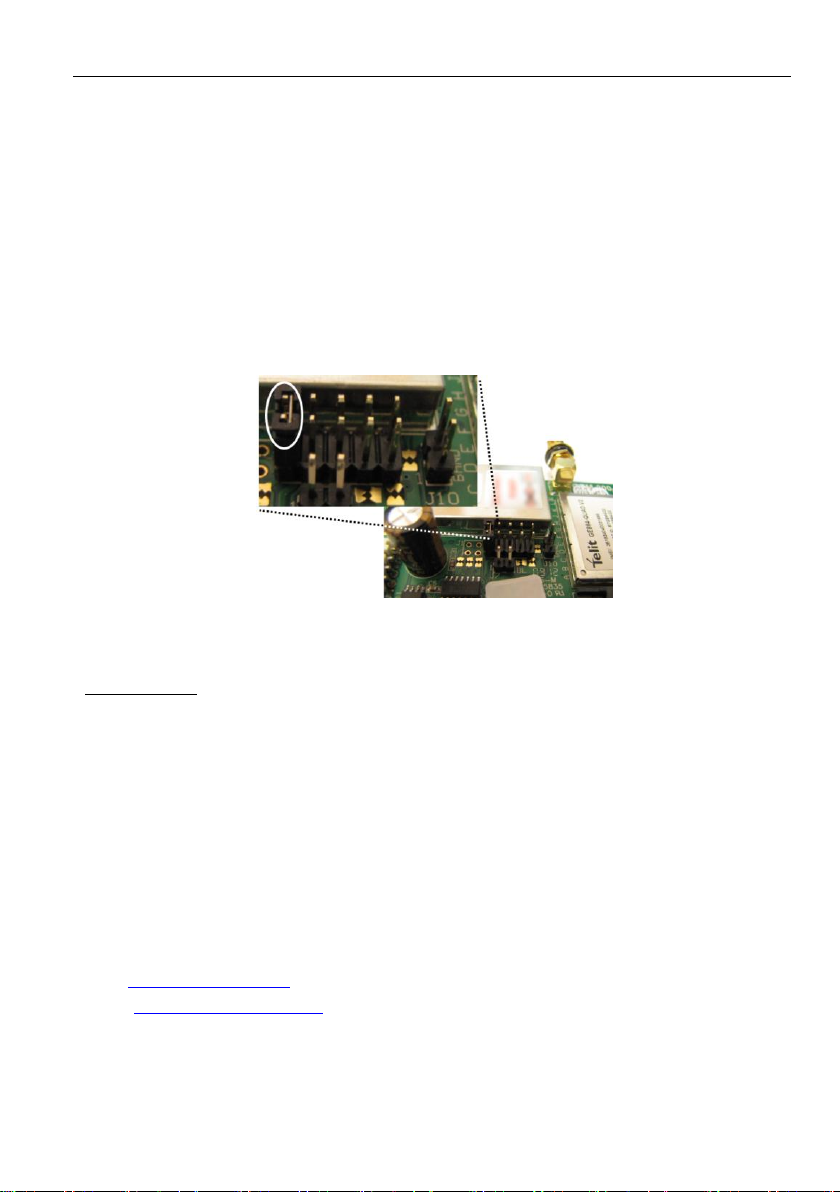
GSM Full rate jumper (Voice channel only)
The GSM Full rate jumper is to be use when the GSM-200 is transmitting in the Voice channel but
transmissions are not received in the Monitoring Station. Since this may be a network load related
problem, transmitting in Full rate (i.e., wider bandwidth) may be a solution.
Starting version 3.12, the communicator’s GSM rate can be set by a new jumper, J1 (see the next
figure). When the jumper is in place, the GSM-200 will transmit (in the Voice channel only) in Full
rate; without the jumper the communicator will transmit in Full or Enhanced full or Half rate,
depending on the cellular network load and characteristics.
Figure 8. GSM Full rate jumper
Limited warranty
PIMA Electronic Systems Ltd. shall have no liability for any death, personal and/or bodily injury and/or
damage to property or other loss whether direct, indirect, incidental, consequential or otherwise, based on a
claim that the Product failed to function.
Copyright 2012 by PIMA Electronic Systems Ltd. All rights reserved. E&OE
PIMA Electronic Systems Ltd.
5 Hatzoref st., Holon 58856
ISRAEL
Tel: +972.3.6506414
Fax:+972.3.5500442
Web: www.pima-alarms.com
Email: support@pima-alarms.com